
Abstract
Vertical axis wind turbine is a special type of wind-force electric generator which is capable of working in the complicated wind environment. The self-starting aerodynamics is one of the most important considerations for this kind of turbine. This article aims at providing a systematic synthesis on the self-starting aerodynamic characteristics of vertical axis wind turbine based on the numerical analysis approach. First, the physical model of vertical axis wind turbine and its parameter definitions are presented. Secondary, the interaction model between the vertical axis wind turbine and fluid is developed by using the weak coupling approach; the numerical data of this model are then compared with the wind tunnel experimental data to show its feasibility. Third, the effects of solidity and fixed pitch angle on the self-starting aerodynamic characteristics of the vertical axis wind turbine are analyzed systematically. Finally, the quantification effects of the solidity and fixed pitch angle on the self-starting performance of the turbine can be obtained. The analysis in this study will provide straightforward physical insight into the self-starting aerodynamic characteristics of vertical axis wind turbine.
Introduction
Vertical axis wind turbine (VAWT) has become popular research topic in recent years because it has better aerodynamic performance than the horizontal axis wind turbine under the complicated wind environment,1–3 and therefore has tremendous potential applications at the urban environment, where the wind is very turbulent and unsteady.
Due to the complexity of the flow around the turbine, a good understanding on the aerodynamic characteristics, especially for the self-starting performance of the VAWT, is very important. Many researchers have focused on this issue: Kentfield 4 concluded that the VAWT cannot self-start without external assistance through the analysis of wind-driven water pumpers. Later, this conclusion was also indicated by Ackermann and Söder. 5 Biadgo et al. 6 investigated the performance of a straight-type VAWT by using numerical and analytical method. The results also indicated that the VAWT using NACA0012 airfoil with solidity of 0.15 would generate negative torque at low tip speed ratios, therefore leading to its inability for self-starting. Hill et al. 7 applied wind tunnel tests and numerical studies to investigate the self-starting characteristics of an H-rotor Darrieus turbine under steady wind conditions. It is found that the turbine with solidity of 0.33 can self-start under uniform free stream velocity of 6 m/s. Further investigation by Worasinchar et al.8,9 indicated that the unsteadiness aerodynamic, which is the similar as flapping wing mechanism, associated with the rotor is the key solution for the self-starting ability of the turbine. However, the details of the flow field were not considered in their study. To explore the self-starting performance of a Darrieus turbine, Dominy et al. 10 developed a numerical simulation to determine the parameters that govern the self-starting capability of the turbine, and the results indicated that a lightly loaded three-bladed rotor always has the potential to self-start under steady wind conditions, whereas the starting of a two-bladed device is dependent on its initial starting orientation.
In summary, the aforementioned studies offer an inconsistent finding about the self-starting capability of the VAWT, which indicates that the self-starting performance of the VAWT is still not fully understood. To this end, this article aims at investigating the effects of solidity and fixed pitch angle of the straight-type VAWT on its self-starting aerodynamic characteristics based on the numerical analysis approach. According to the study by Mohamed, 11 Castelli et al., 12 and Untaroiu et al., 13 a two-dimensional (2D) simulation of the straight-type VAWT can be good approximations of three-dimensional (3D) experiments. Therefore, a weak coupling 2D model was developed to simulate the interaction between the rotation turbine and fluid. Analysis results of this work will provide useful information for the design of VAWT. The rest of this article is organized as follows: the physical model of VAWT and its parameter definitions are presented in section “Physical model of VAWT and its parameter definitions”; a description of the numerical method is presented in section “Numerical method for solving the interaction between VAWT and fluid.” The results and discussions are presented in section “Results and discussion,” and the conclusions are drawn in the last section.
Physical model of VAWT and its parameter definitions
In order to numerically analyze the aerodynamic characteristics of the self-starting VAWT, a turbine with three NACA0018 airfoils is employed in this article; the structure of the turbine is as shown in Figure 1, where U∞ is the free stream velocity, ωR is the turbine rotational speed, Ur is the resultant velocity approaching to the blade section, α is the angle of attack of the airfoil, β is the fixed pitch angle, θ is the azimuth angle, Ft and Fn are the tangential force and normal force, respectively. Based on the geometry from Figure 1, the angle of attack α can be defined as

where λ is the tip speed ratio that can be defined as

The energy of the turbine at an arbitrary angular velocity ω is defined as

While the energy coefficient is calculated by

where ρ is the fluid density.
The mean energy coefficient when the turbine reaches steady rotation status can be calculated by

where T is the rotation cycle. Note that when the turbine finishes self-starting process, the positive energy is the energy absorbed by the turbine from wind, and the negative energy is the energy dissipated by the viscous damping, and therefore only the positive part is considered in equations (4) and (5), and the negative part is fixed at 0.
There are two relative nondimensional parameters, namely, Reynolds number Re and solidity σ. The definitions of them are given as

where ν is the fluid kinematic viscosity, N is the number of the blades, and c is the chord of the blade. Note that the flow characteristic of the turbine is determined by Re, and the unsteady characteristics of the flow are determined by σ. The main features of the turbine in the simulations are summarized in Table 1.

Structure of the turbine.
Main features of the turbine.

Numerical method for solving the interaction between VAWT and fluid
Fluid solver
Based on the Reynolds number (at range of 104–105) of urban environment of the turbine working in, it is assumed that the flow around the turbine is incompressible and turbulent. Therefore, the governing equations for fluid flow are the 2D unsteady, incompressible, and turbulence Navier–Stokes (N-S) equations that can be given by
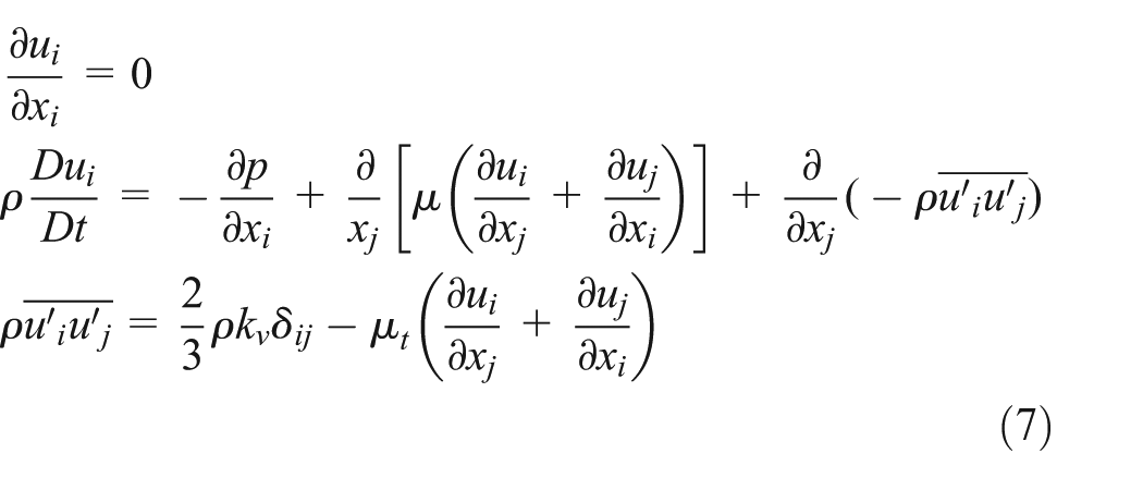
where i and j are the subscripts of the velocity, ui and uj are the velocity vectors, p is the pressure, µ is the fluid dynamic viscosity,
In order to solve the governing equation (7), re-normalization group (RNG) k – ε turbulence model which is suggested for VAWT simulation by Howell et al. 14 and Almohammadi et al. 15 is employed to solve the Reynolds stress. The equations are solved using the Fluent 6.3 which is based on the finite-volume method. The first-order upwind algorithm is employed for space discretization and first-order implicit algorithm for time discretization. Meanwhile, the coupling between the pressure and the velocity is achieved by means of the SIMPLEC algorithm.
Passive rotation solver
Based on the Newton’s second law, the passive rotation of the turbine is determined by

where J is the inertia moment of the turbine and Q is the aerodynamic torque of the turbine.
To solve the governing equation (8), the finite difference method is employed, where a central difference scheme is applied in the discretization of the passive rotation angle in equation (8), and the equation then becomes

where Δt is the iteration time step, and the superscripts t + Δt, t, and t − Δt indicate a value at the corresponding time step. Qt is the aerodynamic torque at the current moment which can be obtained after the flow field is solved.
Coupling of fluid and passive rotation of VAWT
A weak coupling method is employed to solve the interaction of fluid and turbine. In this method, at each time step the fluid field is solved first using the solver fluent where the aerodynamic torque on the turbine can be obtained, and then the passive rotation angle of the turbine under the torque is determined using the finite difference solver which is embedded in fluent using the user-defined function (UDF). In the next time step, the fluid flow is solved for the turbine with an updated position angle and a new aerodynamic torque is obtained. The dynamic mesh technique is used in updating the turbine’s position at each time step. The fluid flow and the turbine’s rotation are solved alternatively. In such a way, the fluid flow and the turbine’s rotation are coupled so that the fluid–turbine interaction is taken into account properly. The details of the coupling process are described in Figure 2.

Schematic of fluid–turbine interaction process.
Grid generation and boundary conditions
A hybrid (triangular grid and quadrilateral grid) mesh system is employed where a C-type computational domain (shown in Figure 3(a)) containing an outer domain, a middle domain, and inner rotation domain is used. To effectively capture the flow field around the turbine, 10 rows of boundary layer are used to encompass the entire blades in the rotating domain (shown in Figure 3(b)) which rotates according to the turbine, and triangular cells are used in the middle domain where remeshing takes place at each time step; the outer domain is stationary for the whole simulation process.

Mesh system of the VAWT: (a) hybrid mesh system and (b) middle and rotation domains.
No-slip wall boundary condition is applied on the surface of the blade. An incoming flow from left to right is applied on the left computational domain and the boundary condition is given by

The pressure outlet is applied on the right computational domain and the boundary condition is given by

where P∞ is the standard atmospheric pressure.
The symmetry is applied on the top and bottom computational domain and the boundary condition is given by

where ϕ is the generalized variable, ϕ = [u, v, p, k, ε], and n is the normal direction.
Method validation
The grid sensitivity study was carried out first to evaluate the independence of the numerical results on the mesh size. Some specified unsteady flow around a three-bladed straight-type VAWT with β = 0°, σ = 0.60, J = 0.0367 kg m2, and U∞ = 6.0 m/s was simulated. The involved grids comprised 1.40 × 10⁵ mixed cells around the blade when the first grid was located at 0.00025 c from the blade surface, 8.65 × 10⁴ mixed cells around the blade when the first grid was located at 0.0005 c from the blade surface, and 5.28 × 10⁴ mixed cells around the blade when the first grid was located at 0.001 c from the blade surface. Each grid was computed until steady rotation velocity has been established. The results of rotation velocity and energy coefficient are shown in Figure 4. The figure shows that there is magnitude difference between different grids; however, the steady rotation velocity and also the energy coefficient of the first two grid schemes are in good agreement. Therefore, at about 1.40 × 10⁵ mixed cells around the blade, the first grid located at 0.00025 c from the blade surface was employed for the next simulations.

Time variation in rotation velocity and energy coefficient of the VAWT with different grid schemes: (a) passive rotation velocity of the turbine and (b) the energy coefficient of the turbine.
A typical case which was experimentally studied by Hill et al. 7 and also numerically studied by Untaroiu et al. 13 is employed to test the reliability of the present numerical method for simulating the passive rotation of three-bladed straight-type VAWT. The simulation parameters are as follows: c = 0.083 m, σ = 0.664, β = 0°, J = 0.03 kg m2, and U∞ = 6.0 m/s. The resulting passive rotation velocity is plotted against time as shown in Figure 5, where the results by Hill et al. 7 and Untaroiu et al. 13 are also presented, and a nondimensional time t′ which is defined by t′ = t/tp (tp is the time when steady rotation velocity ω was established) is employed for comparing. It is seen from the figure that there is magnitude difference between the numerical results and the experiment data before the self-starting finished. The difference can be due to the combined effects of finite blade length and spokes drag, as described by Castelli et al. 12 However, the present numerical result could be able to capture the steady passive rotation velocity correctly. Moreover, the variation in steady passive rotation velocity of the present results is closer to the experiment data than the numerical result by Untaroiu et al. 13 which indicates that the present 2D simulation can grasp the main features of the flow when the turbine finished self-starting.

Time variation in angular velocity of the self-start VAWT.
Results and discussion
In order to study the aerodynamic characteristics of the self-starting VAWT, the influences of solidity and fixed pitch angle on the energy coefficient and also flow structure are examined. The Reynolds number Re, the chord of blade c, and the free stream velocity U∞ are kept at the values of 3.41 × 10⁴, 0.083 m, and 6 m/s, respectively.
Effect of solidity
To investigate the effect of solidity on the aerodynamic characteristics of the self-starting VAWT, β is fixed at a value of 0°, and the 2D three-bladed straight-type VAWT with solidity σ = 0.1–1.0 with interval of 0.1 is considered.
The variations in the steady passive rotation velocity, tip speed ratio, steady passive rotation established time, and mean energy coefficient of the VAWT with different solidities are plotted in Figure 6. Three interesting phenomena can be observed in this figure. First, the steady passive rotation velocity monotonously increases with the increase in solidity, on the contrary to the tip speed ratio. Second, the steady passive rotation established time tp first monotonously decreases with the increase in solidity; however, when the solidity crosses over the value of 0.5, the tp keeps almost constant with the increase in solidity. Third, the mean energy coefficient increases with an increase in σ when σ is less than 0.3 and reaches a maximum at σ = 0.3; when σ crosses 0.3, the mean energy coefficient decreases with an increase in σ; however, the decreasing magnitude is not large.

Aerodynamic characteristics of the self-starting vertical axis wind turbine with different solidities: (a) steady passive rotation velocity, (b) tip speed ratio, (c) steady passive rotation established time, and (d) mean energy of the turbine.
It must be emphasized that the performance of the self-starting VAWT is determined by tp and
To analyze the mechanism of how the solidity affects the aerodynamic characteristics of VAWT, three specific VAWTs with σ = 0.1, 0.3, and 1.0 are studied in detail. Figure 7 plots the time history of passive rotation velocity and energy coefficient of the three studied VAWTs. Obviously in the figure the magnitude of the passive rotation velocity increases with an increase in σ, while the tp decreases with the increase in σ. There are phase differences between the power coefficient of the three studied VAWTs, and the energy coefficient of the VAWT with σ = 0.3 has the largest magnitude than the three studied VAWTs.

Time history of passive rotation velocity and energy coefficient of the VAWT with σ = 0.1, 0.3, and 1.0: (a) time history of passive rotation velocity and (b) time history of energy coefficient.
Figure 8 plots the vortices’ contours of the three specific VAWTs considered above. Two typical times t = 2.0 and 15.0 s are considered. It is seen from Figure 8(a)) that the clear separation vortex can be observed for the three studied turbines, and the intensity of the vortex increases with the increase in solidity, which is the reason why the passive rotation speed and energy coefficient increase with the increase in solidity, as shown in Figure 7. It is seen in Figure 8(b) that nearly no separated vortex is observed around the blade surface of the VAWT with σ = 0.1 and 0.3; however, the attached vortex of the VAWT with σ = 0.3 is stronger than the VAWT with σ = 0.1. Meanwhile, the clear vortex separating phenomenon is observed around the turbine blade of the VAWT with σ = 1.0, although it has strongest vortex strength, which indicates that the performance of the VAWT is deteriorated. This is the reason why the VAWT with σ = 0.3 possesses best energy coefficient for the three studied turbines.
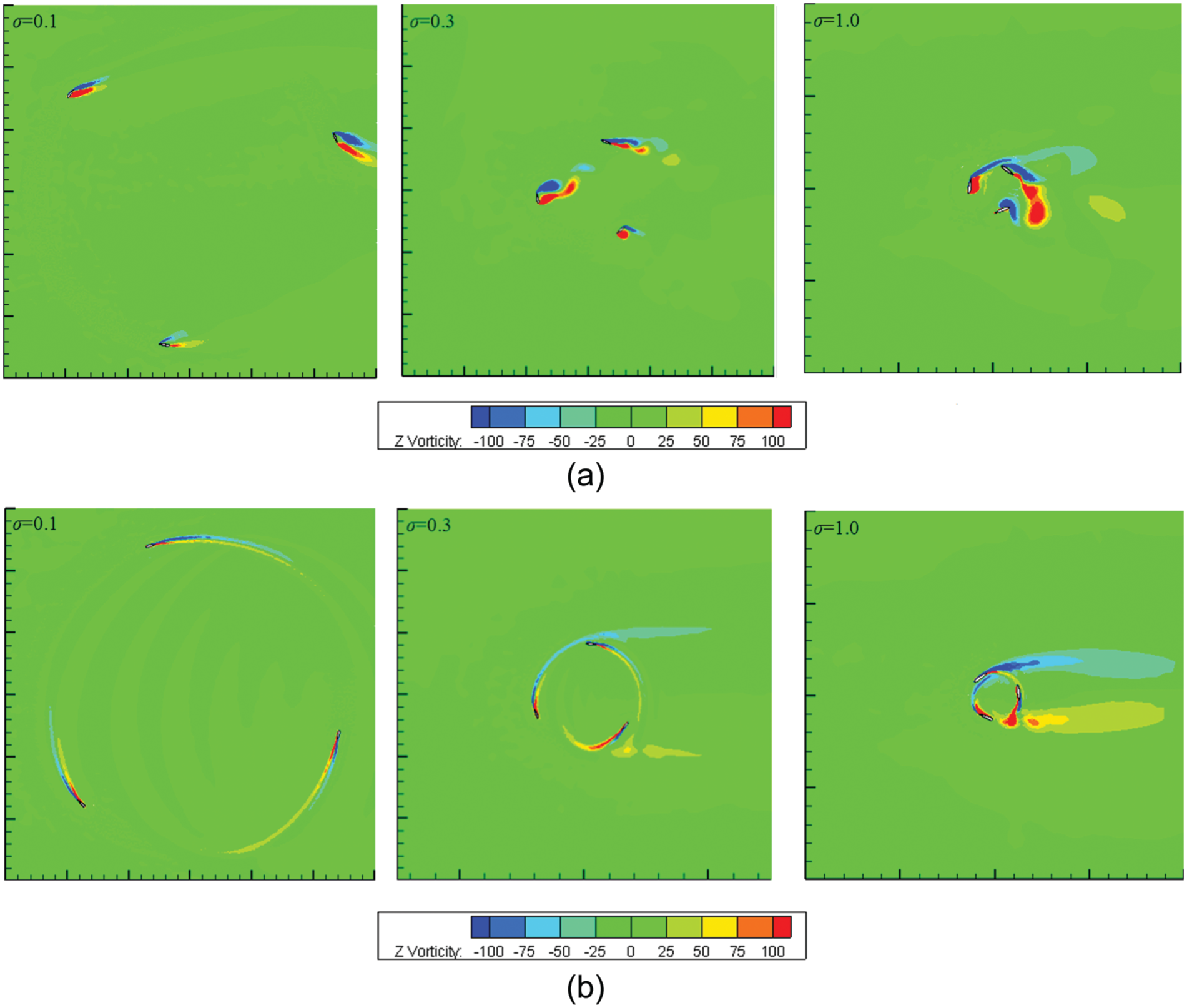
Vortices’ contours of the VAWT with σ = 0.1, 0.3, and 1.0 at (a) t = 2.0 s and (b) 15.0 s.
Effect of fixed pitch angle
To investigate the effect of fixed pitch angle on the aerodynamic characteristics of the self-starting VAWT, σ is fixed at a value of 0.60, and the 2D three-bladed straight-type VAWT with β = −10° to 10° with interval of 2.5° is considered.
The variations in the steady passive rotation velocity, tip speed ratio, steady passive rotation established time, and mean energy coefficient of the VAWT with different fixed pitch angles are plotted in Figure 9. It is seen from Figure 9(a) that two interesting phenomena can be observed from this figure. First, there exists a range of fixed pitch angle (β from −5° to 5°) where the steady passive rotation velocity is affected by β minor; however, they change sharply when β is out of this range. Second, the maximum passive rotation velocity is achieved when β = 0°.

Aerodynamic characteristics of the self-starting vertical axis wind turbine with different fixed pitch angles: (a) steady passive rotation velocity, (b) tip speed ratio, (c) steady passive rotation established time, and (d) mean energy of the turbine.
It is seen in Figure 9(b) that the varying trend of tip speed ratio of the VAWT with different fixed pitch angles is similar to the varying steady passive rotation velocity with the fixed pitch angle. However, when β crosses over 5°, the tip speed ratio is less than 1.0. According to the self-starting definition of VAWT by Lunt, 16 the VAWT is deemed to have started if it has accelerated from rest to a condition where the blade operates at a steady speed that exceeds the wind speed (λ > 1), which indicates that the VAWT with β = 7.5° and 10° cannot self-start.
It is seen in Figure 9(c) that the fixed pitch angle can influence the steady passive rotation established time largely. For the considered VAWT which can self-start (β from −10° to 5°) in this work, tp decreases with β when β is smaller than 0° and reaches a minimum at β = 0°, and when β crosses over 0°, the tp increases with β, which indicates that the VAWT with β = 0° has the fastest time to established steady passive rotation, therefore possessing better self-starting characteristics.
It is clear in Figure 9(d) that the fixed pitch angle can also influence the mean energy coefficient of the VAWT largely. The mean energy coefficient increases with an increase in β when β is less than −2.5° and reaches a maximum at β = −2.5°; when β crosses −2.5°, the mean energy coefficient decreases with an increase in β; especially when β crosses 5°, the mean energy coefficient drops sharply, which indicates that the performance of the VAWT is deteriorated.
To explore the mechanism of how the fixed pitch angle affects the aerodynamic characteristics of VAWT, two specific VAWTs with β = −2.5° and 7.5° are studied in detail. Figure 10 plots the time history of passive rotation velocity and energy coefficient of the two studied VAWTs. Obviously in Figure 10(a) the VAWT with β = −2.5° has larger passive rotation velocity than the VAWT with β = 7.5° almost during the whole self-starting process, and also it has smaller steady passive rotation established time. It is seen from Figure 10(b) that the VAWT with β = −2.5° has larger energy coefficient magnitude than the VAWT with β = 7.5°; however, there are phase differences between the energy coefficient of the two studied VAWTs.

Time history of passive rotation velocity and energy coefficient of the VAWT with β = −2.5° and 7.5°: (a) time history of passive rotation velocity and (b) time history of energy coefficient.
Figure 11 plots the vortices’ contours of the two specific VAWTs considered above. Two typical times t = 4.0 and 18.0 s are considered. It is seen from Figure 11(a) that the clear separation vortex can be observed for both the studied turbines; however, for the VAWT with β = −2.5°, the flow is close to blade surface when the blade rotates upstream, which indicates the turbine possesses enhancement delayed stall mechanic. It is clear in Figure 11(b) that nearly no separated vortex is observed around blade surface and inner rotation domain of the VAWT with β = −2.5°; however, for the VAWT with β = 7.5°, the clear vortex separating phenomenon is observed around the turbine blade, and also the separated vortex is generated at the inner rotation domain; this separated vortex may interact with the turbine blade in further rotation processing and reduce the instantaneous angle of attack of the blade. This is the reason why the VAWT with β = −2.5° has better self-starting aerodynamic characteristics.

Vortices’ contours of the VAWT with β = −2.5° and 7.5° at (a) t = 4.0 s and (b) 18.0 s.
Conclusion
In this article, a numerical experiment is carried out to investigate the aerodynamic characteristics of the self-starting VAWT with different solidities and fixed pitch angles, where the incompressible N-S equations coupled with passive rotation of the VAWT are solved. The flow field and energy coefficient are analyzed for different solidity and fixed pitch angle turbines and the results show that the solidity and fixed pitch angle influence the aerodynamic characteristics of the VAWT greatly. The maximum mean energy coefficient (0.10) is achieved when σ = 0.3; however, the minimum self-starting time tp (8.0 s) is achieved when σ is located at a range of 0.6–1.0; the solidity cannot make the VAWT having both the small tp and large
Footnotes
Academic Editor: Mohammad Reza Salimpour
Declaration of conflicting interests
The author(s) declared no potential conflicts of interest with respect to the research, authorship, and/or publication of this article.
Funding
The author(s) disclosed receipt of the following financial support for the research, authorship, and/or publication of this article: This work was supported by the Key Laboratory of Metallurgical Equipment and Control of Education Ministry, Wuhan University of Science and Technology Foundation (2015B07) and National Science and Technology Support Program (project no. 2012BAH85F01).