
Abstract
This article presents a design of pilot-assisted load control valve with load velocity control ability and fast opening feature based on static and dynamic modeling. Traditional load control valves do not have the load velocity control ability and its opening feature is very poor because the high spring stiffness comes along with the pressure–spring balance–based principle. Some improvement has been done by employing a two-stage pressure–pressure balance principle to make a load control valve to achieve load velocity control ability while the opening feature was not improved much. In this design, another pressure–pressure balance principle is proposed to make the load control valve achieve load velocity control ability and fast opening closing feature at the same time. Static modeling method based on force balance and Bernoulli orifice pressure-flow equation is used to design the load velocity control ability of the valve. Dynamic modeling method based on Newton’s second law and fluid continuity equation is used to optimize the parameters to give the proposed load control valve a fast opening feature. An actual load control valve was developed according to the above methods and the test results show both good load velocity control ability and fast opening feature of the design, which validates the potentiality of the proposed design in many applications.
Introduction
Load control valves (LCVs), also named motion control valves, counterbalance valves, or over-center valves and so on in the literature, are generally used as a part of hydraulic control systems for applications in which overrunning load exists, for example, hydraulic winch and mobile crane booming system. 1 An LCV is designed to restrict the oil flow from an actuator to prevent possible cavitation at the inlet port of actuator which will occur if the load causes the actuator to move faster than the oil flow supplied by the pump. 2 Therefore, LCV commonly has multiple functions of a pilot throttle valve and a check valve.
For the research of LCV, both static and dynamic performance requirements should be satisfied to achieve good performance of the whole system. For static performance, if the LCV can control the flow rate from the hydraulic actuator to oil tank, we say the LCV has load velocity control ability, which requires no additional valves to control the load velocity. This will simplify the system and save the cost greatly. For dynamic performance, when given a step opening signal, the LCV should open fast and when the opening signal disappears, the valve should close fast. A fast opening feature gives the whole system a fast response and fast closing feature assures the load will be stopped at a desired position. 3 Giving the LCV a fast close feature is easy using several methods such as employing a high stiffness spring or designing a closing orifice for the closing of the main spool separately. Compared with the fast close feature, load velocity control ability and fast opening feature are much more difficult to achieve on the valve. A number of researchers are trying to solve this problem. For example, in the hydraulic booming system of a mobile crane, whether the LCV has load velocity control ability or not directly affects the hydraulic system complexity. If a system employs an LCV with load velocity control ability, the system circuit can be significantly simplified. 3 For applications such as hydraulic winch, the factor that limits the response of the whole system is the opening closing feature of the LCV. 4
Traditional LCVs are all designed based on the pressure–spring balance principle, for which the load velocity control ability is very hard to add to the valves and the improving of opening feature is constrained. In traditional LCV, spool displacement is determined by the force balance of pilot pressure and the control spring. This pressure–spring balance principle has the advantage of simple structure and high reliability. The spring stiffness is often very high to make sure the valve does not open when there occurs a pilot pressure disturb. While as a result, the pilot pressure must be high, which leads to additional energy consumption.5,6 Due to the high spring stiffness, the stroke of the spool is often very short and accordingly a gradient orifice is almost impossible to achieve on such a short stroke. As a result, traditional LCVs always can only be used for bang-bang flow rate control, which makes the system have to employ another valve to control the load velocity. Meanwhile, the improving of the opening feature is also constrained by the high stiffness. That is because when opening, the spring force plays the role of resistance force of the spool motion, and high spring stiffness brings large spring force, making the opening of the spool slow. In addition, studies of Nordhammer et al. 7 and Zähe 8 showed that a hydraulic system with a traditional LCV trends to be unstable in some part of the cylinder stroke. Previous study also pointed out that the unstable problem trends to occur more seriously when the system is load sensing. 9 Some work has been done to design new LCV based on the traditional pressure–spring balance principle to improve the performance and energy assumption of the whole system, but the opening response improves little.10,11
There are new LCV designs employing totally different principle from traditional ones. A hydraulic follow principle is brought up by researchers. 12 The design is based on two-stage structure. The main spool of the valve moves following with the pilot spool, and the force balance of the main spool is mainly achieved by the pressures of different chambers. 12 This pressure–pressure balance principle makes the main spool of the valve has a long stroke, which allows the designing of a gradient orifice on the stroke to make the valve has load velocity control ability.13,14 As the opening of the pilot orifice is determined by the displacement difference of the pilot and main spools, and because the main spool follows the pilot spool, the opening of the pilot orifice cannot be very big during the opening process. This constrains the improvement of the opening feature. 3
This article presents another pressure–pressure balance principle different from the hydraulic follow principle. In the design, the opening procedure is similar to a pilot-assisted pressure relief valve, and the main spool moves according to the net pressure force worked on it instead of following the pilot spool. Thus, the opening of the pilot orifice is determined only by the displacement of the pilot spool. Therefore, compared with the hydraulic follow principle, the pilot orifice can open larger in the opening process, which improves the opening time significantly. In addition, because the pressure–pressure balance–based principle instead of the traditional pressure–spring balance–based one is used, the stroke of the main spool is long enough to design a gradient orifice on it, making the design obtain load velocity control ability too. In the article, static modeling method based on force balance and Bernoulli orifice pressure-flow equation is used to achieve the load velocity control ability of the valve. Dynamic modeling method based on Newton’s second law and fluid continuity equation is used to optimize the parameters to give the proposed LCV a fast opening feature. An actual LCV was developed according to the above methods and the test results show both good load velocity control ability and fast opening feature of the design, which validates the potentiality of the proposed design in many applications.
Working principle of the proposed LCV
Figure 1 shows the simplified cross section of the designed LCV and its application in crane booming hydraulic system. As indicated in Figure 1, the valve consists of pilot piston, control spring, pilot spool, main spool, and so on. In the crane booming system, the main components include a main pump to supply the pressure oil when booming up, a directional control valve (DCV) to decide whether the boom goes up or down, and an operating lever to supply the pilot oil to control both the DCV and LCV. The LCV, which is presented in the dash dot line box, is employed to balance the oil pressure of the non-rod chamber of the booming cylinder when holding the load and to control the oil flow out of the non-rod chamber so as to control the load velocity when booming down. There is also a charge pump together with a check valve to offer a certain low pressure for the rod chamber of the booming cylinder.
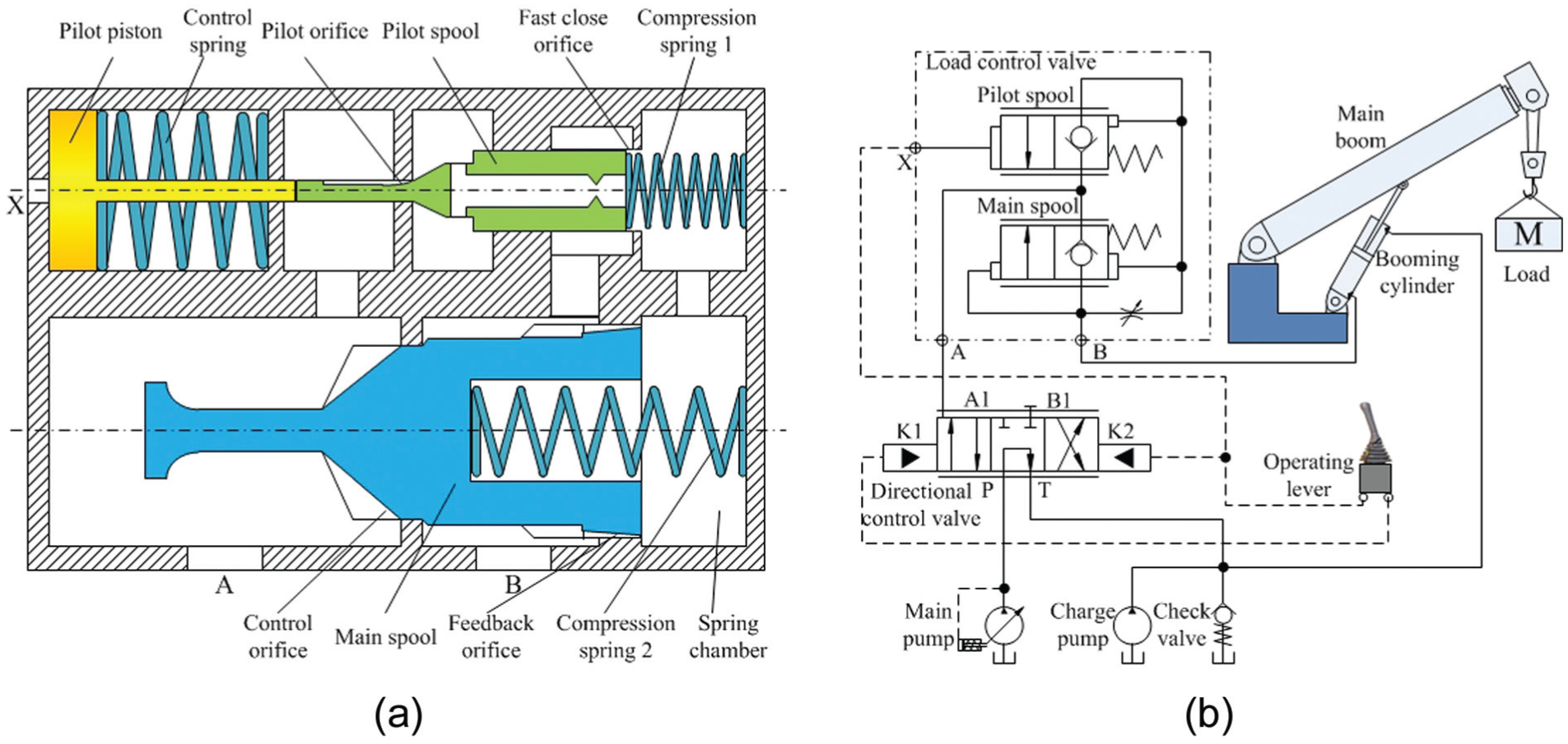
Simplified cross section of the proposed LCV and its application.
When booming up, the LCV works only as a check valve and the booming velocity is determined by the DCV. As the operating lever is on the booming up position, pressure oil given by the operating lever to the K1 pilot port of the DCV pushes the valve works at its left position, and then pressure oil from the main pump goes directly to port A of the LCV. Then, the main spool of the LCV is pushed by the pressure oil rightward to compress the compression spring 2 behind it, resulting in the opening of the control orifice. Because the stiffness of the compression spring 2 is low, the cracking pressure of port A is very low and the oil goes through the control orifice and flows to the non-rod chamber of the booming cylinder from port B. Thus, the load is boomed up by the extension of the booming cylinder.
When booming down, the lowering speed is controlled by the LCV. In addition, the lowering speed has a positive correlation with the pilot pressure (pressure of port X). When the operating lever is on the booming down position, pressure oil is given to both the K2 pilot port of the DCV and the X pilot port of the LCV. Thus, the DCV works at its right position due to the oil pressure of pilot port K2. For the LCV, the pilot pressure of port X pushes the pilot piston rightward to compress control spring 1, and as a result, the pilot spool moves rightward. Because of the movement of the pilot spool, the fast close orifice closes, cutting the connection of port B and the spring chamber. At the same time, the pilot orifice opens, through which the oil of the spring chamber flows to port A, resulting in the pressure decrease in the spring chamber. As the spring chamber pressure decreases, the force balance of the main spool is interrupted and the main spool moves rightward, leading to the opening of the control orifice. As a consequence, the oil in the non-rod chamber of the booming cylinder flows into port B, through the control orifice, then out of port A, and goes back to the oil tank. The feedback orifice becomes bigger when the main spool moves rightward, which causes the rising of the spring chamber pressure. Finally, the main spool retains its force balance at a certain position and the position has a positive correlation with the pressure of port X. It is clear that the more the main spool moves rightward, the bigger the opening of the control orifice, and the larger the flow rate through the LCV. Thus, a positive correlation between the pilot pressure and the lowering speed of the load is established.
Similar to former designs, a fast close orifice is designed to make the valve close quickly when pilot pressure disappears. When the lowering action of the load comes to an end, the pilot pressure disappears and the pilot spool along with the pilot piston moves back due to the restoring force of both the control spring and compression spring 1. As the pilot spool comes back to its initial position, the fast close orifice opens, which leads to a direct connection between the spring chamber and port B. The pressure oil of port B flows into the spring chamber through fast close orifice and the pressure of the spring chamber increases swiftly. Then, the main spool moves back to its initial position as a result of the increasing spring chamber pressure. Thus, a fast close feature is gained by introducing the fast close orifice to the valve.
Design of the load velocity control ability based on static modeling
There are two major problems for the design of the load velocity control ability, one is the stroke design of the pilot and main spools and the other is the design of the control orifice on the main spool. The two major problems are solved by the method of static modeling as below.
Force balance formulation of the pilot spool and pilot piston assembly is employed to design the stroke of the pilot spool. Force balance and Bernoulli orifice pressure-flow equation are employed to design the stroke of the main spool.
For the pilot spool and pilot piston assembly, the force balance can be formulated with friction force neglected as

where pp and pL are the pilot pressure and load pressure (pressure of port B), respectively; Ap and Ar express the areas of the pilot piston and the end face of the left side of the pilot spool, respectively; FC0 and kC are the initial force and stiffness of control spring, respectively; xps is the displacement of pilot spool assembly; and FC1 is the force of compression spring 1. Because a low stiffness compression spring 1 is chosen, force FC1 could also be neglected and with an area ratio defined as λ = Ap/Ar, it can be derived that

From equation (2), it is easily concluded that once the stroke of the pilot spool displacement xps is determined, the stroke of pilot pressure pp is only affected by load pressure pL and area ratio λ determines how much the load pressure affects the stroke of the pilot pressure. After the stoke of the pilot spool and the parameters of the control spring are determined, the relationship of the pilot pressure stroke, the load pressure and the area ratio is described in Figure 2.

Relationship between pp, λ, and pL.
As illustrated in Figure 2, when load pressure pL increases, the stroke of pilot pressure pp decreases and the area ratio λ affects how much pL affects the pilot pressure stroke. A relatively constant pilot pressure stroke is required in the design of an LCV, so a relatively large area ratio λ must be chosen. As shown in the figure, with λ larger than 60, the pilot pressure stroke changes little with pL. Because the larger λ is, the larger the final size of the valve will become; an area ratio of 64 is determined finally, taking both the pilot pressure stroke and the valve size into consideration.
As for the stroke design of the main spool, it can also be derived from the force balance of it

where pA and psc are the pressures of port A and the spring chamber, respectively; A1 and A2 are the areas of the two end faces of the main spool; and FC2 is the force of compression spring 2.
In addition, because the flow rate through the feedback and pilot orifices named as Qf and Qp are equal, it can be formulated according to the Bernoulli orifice pressure-flow equation that

where c is the discharge coefficient, and Afo and Apo are the metering areas of the feedback and the pilot orifices, respectively.
As pA and FC2 are small enough to be neglected, the relationship between Afo and Apo can be derived from equations (3) and (4), which is shown as follows
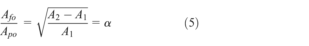
As is formulated by equation (5), when the main spool reaches its final position, a certain proportional relationship between the feedback and the pilot orifice areas exists, which gives direction for the designing of the main spool stroke. After the stroke of the pilot spool and the shape of the pilot orifice are determined, if the feedback area Afo is carefully designed to the value of αApo at the end of the desired main spool stroke, the determination of the main spool stroke is realized.
After the designing of the pilot and main spools, so as to realize load velocity control ability on the LCV, it is still necessary to design the control orifice on the main spool stroke to realize a gradient control orifice metering area. Taking both manufacturing difficulty and desired load velocity control performance into consideration, the control orifice is designed as illustrated in Figure 3. The designed control orifice can be manufactured by a milling cutter easily without any complex process.

Design of the control orifice.
In Figure 3, xms is the displacement of the main spool and Aco is the metering area of the control orifice. The calculation of Aco is conducted by commercial software package FLUENT by importing the three-dimensional (3D) model into the software as well as setting the inlet and outlet pressures and the parameters of hydraulic oil. It is obviously shown that the metering area changes gradient with the main spool displacement, which is required for the load velocity control ability.
Design of the fast opening feature based on dynamic modeling
As illustrated in equation (5), there is a certain proportional relationship between the feedback and the pilot orifice areas when the valve reaches its final working position, which provides the base for the design of the load velocity control ability of the proposed LCV. However, the maximum values of the two areas significantly affect the opening time of the proposed LCV, which has not been investigated yet. In this section, dynamic modeling method is employed to optimize the maximum values of the two areas Apo and Afo.
Because the mass of the pilot piston and spool is much lighter compared with that of the main spool, the dynamic process of the main spool is much longer than that of the pilot piston and spool. As a result, the opening time of the proposed LCV is mainly determined by the dynamic process of the main spool. Therefore, it is reasonable to modeling the motion dynamics of the main spool with the assumption that the pilot orifice opens as a step. The governing equation of the main spool motion can be built based on the Newton’s second law

where mms is the mass of the main spool, Dms is the viscous friction coefficient, fms is the Coulomb friction, and FC2 is the force of compression spring 2, which could be formulated by FC2 = FC20 + xmskC2 with its initial force and stiffness FC20 and kC2. In the equation, the flow force on the spool is neglected. That is because areas A2 and A1 are designed large enough to make sure the flow force is so small compared with the pressure forces that it has little effect on the dynamics of the main spool. The dynamic equation of the spring chamber pressure psc can be formulated based on the continuity equation of hydraulic oil

where E is the bulk modulus of hydraulic oil, Vsc is the initial volume of the spring chamber, and the calculations of Qf and Qp are described in equation (4). In simulation, the value of E is set to 1700 MPa.
Based on the above equations, the dynamic model of the main spool was built in Simulink, which is shown in Figure 4. In the model, main spool dynamics module was built based on equation (6), Afo module is a look-up table module which contains the information of feedback orifice, Qf and Qp modules were built according to equation (4), and psc module was based on equation (7).

Dynamic model of the main spool motions.
The variation in the maximum value of pilot orifice area Apmax has significant effect on the opening dynamics of main spool, which is validated in simulation illustrated in Figure 5. In the simulation, the pilot orifice area is simplified as a step input given at the time of 0.3 s, and the displacement of the main spool is simulated for different maximum pilot orifice areas. Four discrete values of the maximum pilot orifice area are simulated. The values correspond to four values of the pilot orifice parameter which are easy to manufacture compared with other values. In the figure, it is clearly shown that when Apmax are 0.5, 1.0, 1.5, and 2.0 mm2, the opening time of the main spool are 0.7, 0.5, 0.4, and 0.35 s, respectively. The larger the Apmax, the shorter the opening time changes. While for Apmax larger than 1.5 mm2, the effect becomes less significant. In addition, because larger Apmax introduces larger pilot flow rate Qp and Qf which will increase the size of the drain parts of the valve greatly, finally the value of the maximum pilot orifice area is determined to 1.5 mm2 and the maximum feedback orifice area is determined according to equation (5).
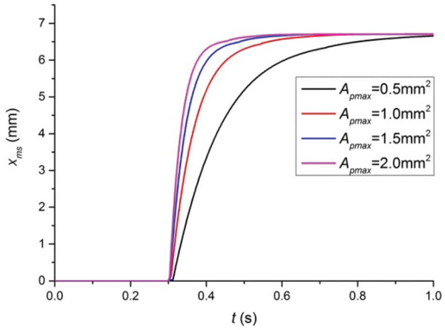
Simulation results of the effect of pilot orifice area on the opening performance of the proposed LCV.
Experiment validation
To validate the LCV design, the experiments were conducted on a test rig whose schematic diagram is illustrated in Figure 6. Three pressure transducers were used to measure the pressure of port A, port B, and port X. A flow meter was used to measure the flow rate through the valve. A computer combined with a National Instruments (NI) data acquisition (DAQ) card was used to acquire the experiment data and control the amplifier. When testing the load velocity control ability of the valve, the manual directional valve works at its left position, the directional valve 2 works at its left position, and the cartridge valve keeps close. The directional valve 1 works at its left position, too. The load pressure is determined by the hydroelectrical relief valve and keeps constant during the test. The variation in pilot pressure is determined by the proportional reducing valve controlled by the computer through the DAQ card and the amplifier. For the response of pilot pressure step, the manual directional valve is at its left position, the directional valve 2 works at its left position, and the cartridge valve keeps close. The proportional reducing valve is set at the desired pressure by the computer. At first, the directional valve 1 is at its right position and port X is connected to the oil tank. Then, the directional valve 1 is operated to its left position and the connection of port X and the oil tank is cut. Therefore, a pilot pressure step is achieved.
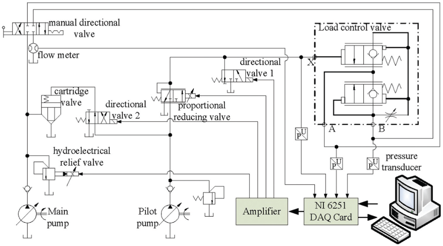
Schematic diagram of the test rig.
Figure 7 shows the experiment data of the load velocity control ability of the proposed LCV; the experiment was conducted with the load pressure of 1 and 4 MPa separately. For 1 MPa load pressure, the result shows that the opening pilot pressure is about 1 MPa and the flow rate QM reaches its maximum value when the pilot pressure gets to 1.7 MPa. The experimental result of 4 MPa load pressure shows that the opening pilot pressure pp is about 1 MPa and when pp rises above 1.4 MPa, the main flow rate through the control orifice QM gets to its maximum value of 110 L/min. There is an even better proportional relationship between QM and pp in the interval of 1–1.4 MPa than that of 1 MPa load pressure. The experiment data indicate that the LCV has good load velocity control ability.

Experiment result of the load velocity control ability of the proposed LCV.
The pressure–pressure balance–based principle instead of the traditional pressure–spring balance explains the reason of the load velocity control ability. As introduces in the load velocity design section, the pressure–pressure–based principle allows the choosing of a low stiffness compression spring 1. That is because the compression spring no longer plays the role of balancing the pressure force. The low stiffness compression spring makes sure the stroke of the main spool is long enough to design a gradient control orifice on it, making the design obtain load velocity control ability.
Figure 8 shows the experiment data of the opening feature of the LCV. The experiment was conducted when the load pressure was kept constant at 5 MPa and the pilot pressure ensured the valve open fully. The pilot pressure signal appeared at 2 s. The result shows that the proposed LCV opened steadily and got to its final state in 0.8 s. The LCV for comparison based on hydraulic follow principle proposed by Haussler et al. 12 got to its final state in 1.05 s. The opening time deceases for 23.8%, which validates the proposed design and the optimization of the Apmax. The final opening time is a little longer than the simulation above, which is because the dynamics of the pilot piston and spool is simplified in simulation and it is very hard to achieve an ideal step pilot pressure in reality.
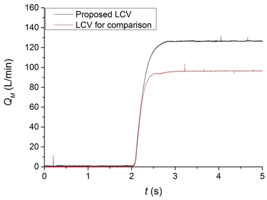
Experiment result of the opening feature of the proposed LCV.
Novel pressure–pressure balance principle different from that of hydraulic follow principle makes the valve opens faster than that of hydraulic follow principle. In the proposed design, the opening procedure is similar to a pilot-assisted pressure relief valve, in which the main spool moves according to the net pressure force worked on it. As introduced above, the pressure force on the main spool is determined by the opening of the pilot orifice. In addition, the opening of the pilot orifice is determined by the displacement of the pilot spool alone. While in the hydraulic follow principle–based design, the main spool moves following the pilot spool. The opening of the pilot orifice is determined by the displacement difference of the pilot spool and the main spool. Because the main spool follows the pilot spool, the opening of the pilot orifice cannot be very big during the opening process. Therefore, compared with the hydraulic follow principle, the pilot orifice can open larger in the opening process, which improves the opening time significantly.
Conclusion
This article presented a design of a pilot-assisted LCV with load velocity control ability and fast opening feature based on static and dynamic modeling. In this design, a novel pressure–pressure balance principle was proposed, which made the LCV achieve load velocity control ability and fast opening closing feature at the same time. Static model based on force balance and Bernoulli orifice pressure-flow equation was given to design the load velocity control ability of the valve. A certain proportional relationship between the feedback and the pilot orifice areas was derived from the static model. Dynamic model of the main spool motions based on Newton’s second law and fluid continuity equation was built to optimize the parameters and further to give the proposed LCV a fast opening feature. An actual LCV was developed, and test results showed good load velocity control ability with load pressure at 1, 4 MPa, and so on. Compared with the LCV based on hydraulic follow principle, the opening time deceases for 23.8%. The proposed design provides guidance for the design of other hydraulic valves especially LCVs.
Footnotes
Academic Editor: Pietro Scandura
Declaration of conflicting interests
The author(s) declared no potential conflicts of interest with respect to the research, authorship, and/or publication of this article.
Funding
The author(s) disclosed receipt of the following financial support for the research, authorship, and/or publication of this article: This project was supported by the National Natural Science Foundation of China (No. 51275451 & No. 51575476), Science Fund for Creative Research Groups of National Natural Science Foundation of China (No. 51221004), Major State Basic Research Development Program of China (973 Program) (No. 2013CB035400), and National High-tech R&D Program of China (863 Program) (No. 2013AA040203).