
Abstract
From the perspective of vehicle dynamics, the four-wheel independent steering vehicle dynamics stability control method is studied, and a four-wheel independent steering varying parameter linear quadratic regulator control system is proposed with the help of expert control method. In the article, a four-wheel independent steering linear quadratic regulator controller for model following purpose is designed first. Then, by analyzing the four-wheel independent steering vehicle dynamic characteristics and the influence of linear quadratic regulator control parameters on control performance, a linear quadratic regulator control parameter adjustment strategy based on vehicle steering state is proposed to achieve the adaptive adjustment of linear quadratic regulator control parameters. In addition, to further improve the control performance, the proposed varying parameter linear quadratic regulator control system is optimized by genetic algorithm. Finally, simulation studies have been conducted by applying the proposed control system to the 8-degree-of-freedom four-wheel independent steering vehicle dynamics model. The simulation results indicate that the proposed control system has better performance and robustness and can effectively improve the stability and steering safety of the four-wheel independent steering vehicle.
Keywords
Introduction
In these years, vehicle active safety technology,1,2 pedestrian protection technology, 3 and vehicle accident prevention technology4,5 have became the hotspots in the research of traffic safety, especially about the vehicle active safety technology. As one of the most important active safety technologies, four-wheel steering (4WS) has been popular research since its appearance. Compared with the traditional front-wheel steering (FWS) vehicle, the rear wheels of 4WS vehicle are involved in the control of yaw and roll motions along with the front wheels. This provides excellent stability at high speeds and better maneuverability at low speeds. 6 According to the different control modes, the existing 4WS system can be classified as active rear-wheel steering (ARS, also called traditional 4WS) system, four-wheel active steering (4WAS, combines active FWS and ARS) system, and four-wheel independent steering (4WIS) system. Among them, the most widely researched one is the ARS system and many control methods have been used in it, such as robust control method,7,8 adaptive decoupling control method,9,10 fuzzy control method,11,12 and optimal control method.13,14 However, ARS system employs the rear wheel steering angle as the only control input and selects either side slip angle or yaw rate as the control target. This leads to the limited improvement of vehicle handling stability.
With the development of the electric motor technology and the appearance of steer-by-wire, researches on 4WAS and 4WIS have proliferated. By using 2-degree-of-freedom (DOF) 4WAS vehicle dynamics model, Li and Yu 15 proposed an optimal model following control structure. The proposed control structure which consisted of a feed-forward controller and a feedback controller could make the side slip angle and the yaw rate track the desired values from the reference vehicle model. Men et al. 16 used the 2-DOF 4WAS vehicle model as the internal model and designed a 4WAS internal model control system. Simulating via 11-DOF vehicle model, the 4WAS internal model control system had been shown to have a better performance in vehicle stability task. Lam and his colleagues17,18 proposed a behavior-based steering controller for 4WIS vehicle. The proposed controller was made up of a position controller and a kinematic constraint controller and suitable for non-autonomous vehicle. By analyzing the 2-DOF 4WIS vehicle model, Chen et al. 19 put forward a 4WIS proportional control system. The designed proportional control system could make all wheels have the same transient cornering center and ensure the zero side slip angle of vehicle.
In the above literatures, the research about 4WIS control system was from the perspective of vehicle kinematics, but did not consider the vehicle dynamic characteristics. For this, this article aims to design a 4WIS controller by using linear quadratic regulator (LQR) control scheme from the vehicle dynamics side. Considering that most LQR controllers adopt fixed parameters, which may result in a poor adaptivity, a 4WIS varying parameter LQR (VLQR) controller based on vehicle state is proposed with the help of expert control method. The article first designed an LQR controller of 4WIS vehicle to make the vehicle state follow the desired values. Then, by analyzing the 4WIS vehicle dynamic characteristics and the influence of LQR control parameters on control performance, an LQR control parameter adjustment strategy based on vehicle steering state is proposed to achieve the adaptive adjustment of control parameters. Moreover, in order to improve the performance of control system, a real-coded genetic algorithm (GA) is applied to optimize the VLQR controller. Finally, by applying the proposed VLQR controller to the 8-DOF 4WIS vehicle dynamics model, the effectiveness and robustness of the proposed controller are verified through simulations.
Vehicle dynamics model
In this section, an 8-DOF 4WIS vehicle dynamics model, a 2-DOF 4WIS vehicle model, and a desired vehicle model are developed. The 2-DOF vehicle model and the desired vehicle model are used for the VLQR controller design. The 8-DOF vehicle model is utilized for the simulation.
Vehicle dynamics model for simulation
An 8-DOF 4WIS vehicle dynamics model developed here for simulation purposes includes the longitudinal and lateral motions, the yaw motion, the roll motion, and the rotational motion of four wheels. The mechanical analysis of 4WIS vehicle is shown in Figure 1.
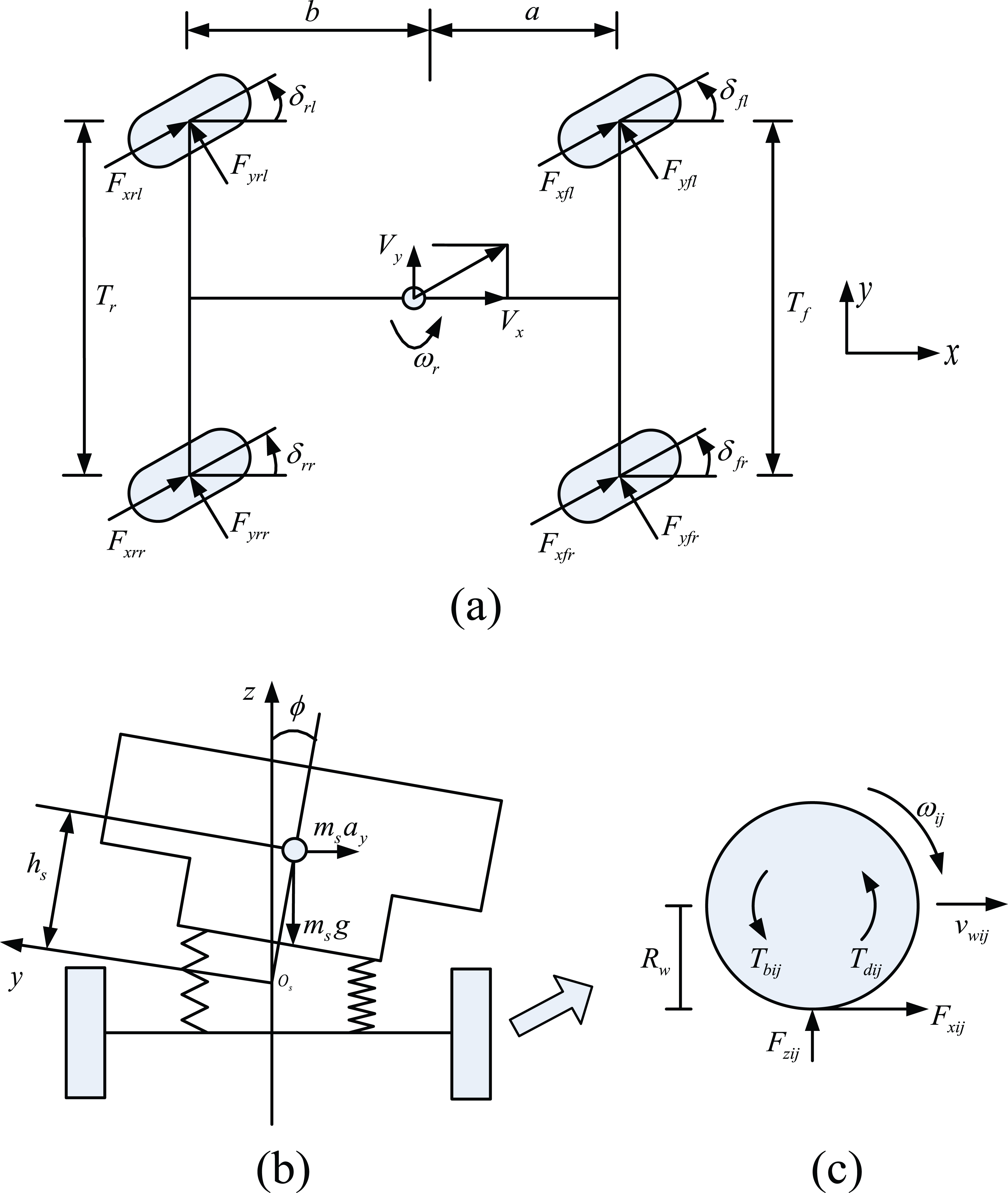
Schematic of 4WIS vehicle mechanical analysis: (a) x–y plane, (b) y–z plane, and (c) wheel rotation plane.
Before introducing the 8-DOF vehicle model, the following assumptions are made:
The vertical and pitching motions of vehicle are not considered.
The suspension is simplified, and there is only the relative roll movement between the sprung mass and the unsprung mass.
The steering mechanism is ignored, and the wheel steering angles are used as the inputs to the 4WIS vehicle dynamics model directly.
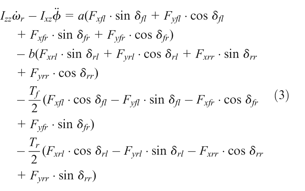
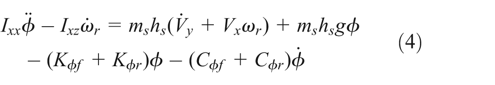
According to Figure 1, the dynamic equations are formulated as follows:20,21
Longitudinal dynamic equation
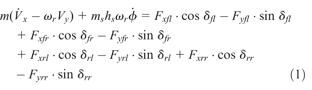
Lateral dynamic equation

Yaw dynamic equation
Roll dynamic equation
Wheels’ dynamic equation

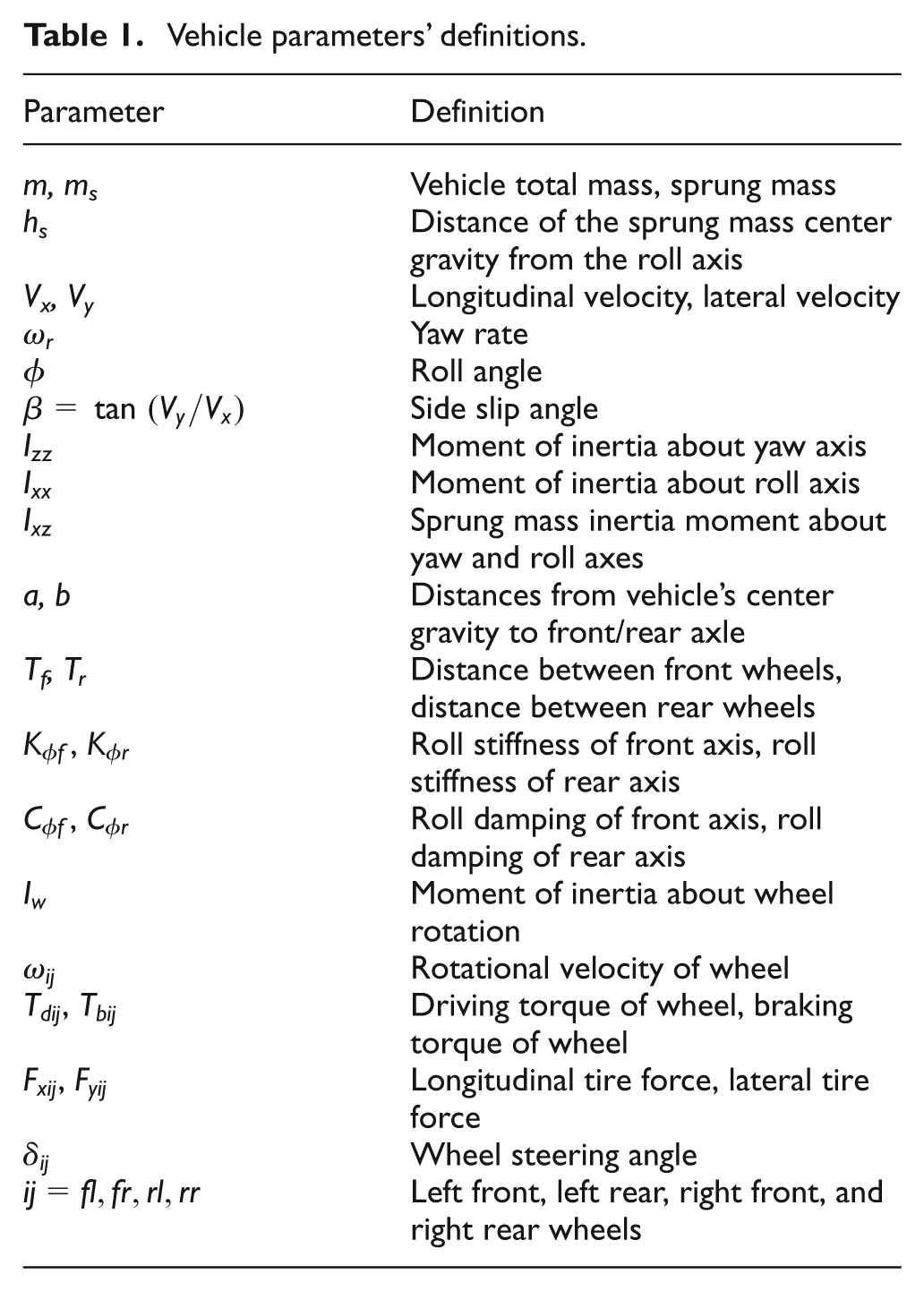
Definitions of the vehicle parameters in the above equations are given in Table 1.
Vehicle parameters’ definitions.
The tire model is one of the most important parts in vehicle dynamics model. In the article, the GIM tire model22,23 is selected to calculate the longitudinal and lateral tire forces (
Vehicle dynamics model for controller design
2-DOF 4WIS vehicle dynamics model
The design of LQR controller relies on state-space model, and therefore, a 2-DOF 4WIS vehicle dynamics model which can efficiently characterize the vehicle steering behavior under non-limit state is also developed in this article. 24 The 2-DOF 4WIS vehicle model consists of the lateral and yaw motions and uses the wheel steering angles as the inputs. The dynamic equations of 2-DOF vehicle model are described as follows

where
The simple linear tire model is used to calculate

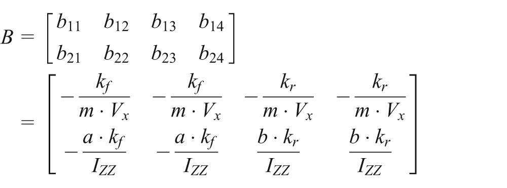
From equations (6) and (7), the state-space equation of 2-DOF 4WIS vehicle model can be expressed as

where

Desired vehicle model
The yaw rate determined by linear 2-DOF FWS vehicle model can be regarded as the ideal yaw rate in the condition of little side slip angle. Not concerning the transient response of yaw rate, the ideal yaw rate can be expressed as

where
To avoid large overshoot and improve the transient response characteristic of yaw rate, a first-order inertial link is introduced into formula (9).

where
Because the longitudinal and lateral tire forces are both limited by tire-road adhesion coefficient

In the vehicle steering process, it is desired to reduce the side slip angle as much as possible. Thus, the ideal side slip angle is set to 0 here. Modeled after formula (10), the ideal side slip angle can be expressed as

where
From equations (10) and (12), the state-space equation of the desired vehicle model can be expressed as

where
VLQR controller
Structure of VLQR controller
Based on the LQR control scheme, a VLQR controller for the 4WIS vehicle is proposed with the help of expert control method, as shown in Figure 2.

Structure of varying parameter LQR controller.
As can be seen from Figure 2, the VLQR controller includes an LQR controller based on model following and a parameter adjuster based on vehicle steering state. The proposed LQR controller can minimize the error between actual vehicle states and desired vehicle states by adjusting the steering angles of four wheels. According to the vehicle speed, the yaw rate error, and the vehicle steering direction, the parameter adjuster automatically adjusts the parameters of the LQR controller according to the pre-defined rules.
LQR controller
The control target of the proposed LQR controller is to track the outputs of the desired vehicle model. The tracking error is defined as follows

From equations (8) and (13), the state equation can be obtained

The nature of LQR control can be regarded as finding the optimal solution to minimize the cost function as follows

where Q and R are the weighting matrices. Specifically, Q is a 2 × 2 positive-semi-definite weighting matrix. R is a symmetric positive-definite weighting matrix.
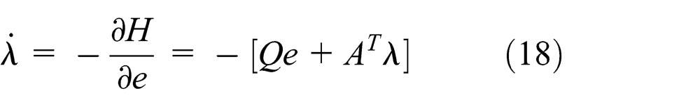
The Hamiltonian function is constructed as follows

The co-state equation can be described as
The LQR control low can be written as

To associate the control output u with the control error e,

Taking the derivative of equation (20), it turns out to be

When time tends to infinity, that is,

where
Using equation (22) to solve the parameter

where P is the Ricatti matrix that can be obtained by solving the Ricatti equation mentioned earlier.
Parameter adjuster
The control parameter is the key factor in influencing the performance of controller. For the LQR controller, the weighting matrices Q and R are the most important components in controller optimization. Most often, the weighting matrices Q and R are determined by trial or error method. After determination of the values of the weighting matrices, they are unchanged. However, vehicle steering motion is comparatively complex, which exists in many kinds of states. Thus, with the help of expert control method, a 4WIS LQR control parameter adjustment strategy based on vehicle steering state is proposed by analyzing the 4WIS vehicle dynamic characteristics and the influence of LQR control parameters on control performance. According to different vehicle steering state and speed, the proposed parameters adjustment strategy can automatically adjust control parameters to ensure better traceability for the desired vehicle model and greater steering stability of 4WIS vehicle.
LQR control parameter analysis
The weighting matrices Q and R can be written as

According to the LQR control scheme, Q represents the importance of each error index of vehicle. Specifically,
R represents the relative importance of energy consumption of each control quantity, and it also represents the steering angle constraint of each wheel in this article. The smaller the value
Through the above analysis, it can be known that, for the proposed 4WIS vehicle LQR controller, the adaptability of the weighting matrix R is more important than that of the weighting matrix Q. These are two reasons for this: (1) Q represents the attention that the control system gives to the vehicle state errors (includes side slip angle error and yaw rate error). By selecting an appropriate value of the matrix Q, the side slip angle error and the yaw rate error can be controlled in ideal range simultaneously. (2) For the different vehicle steering state, the adjusting rules of the wheel steering angle are different. The weighting matrix R can directly affect the wheel steering angle, and therefore, the value of the matrix R needs to be adjusted in different vehicle steering state conditions.
Above all, in order to simplify the adjusting rules of the control parameters, this article focuses on designing the adjusting rules of the weighting matrix R. The weighting matrix Q using fixed value is determined by experience and simulation.
The adjusting rules of LQR control parameter
The values
When vehicle steering, there are two situations: understeer and oversteer. The specific situation is determined by the yaw rate error and the vehicle steering direction. By adjusting the wheel steering angle, the control system increases or decreases the yaw rate to make the vehicle state tracking the ideal state, which guarantees the vehicle stability. Note that the vehicle response is different when different wheel steering angle is adjusted.
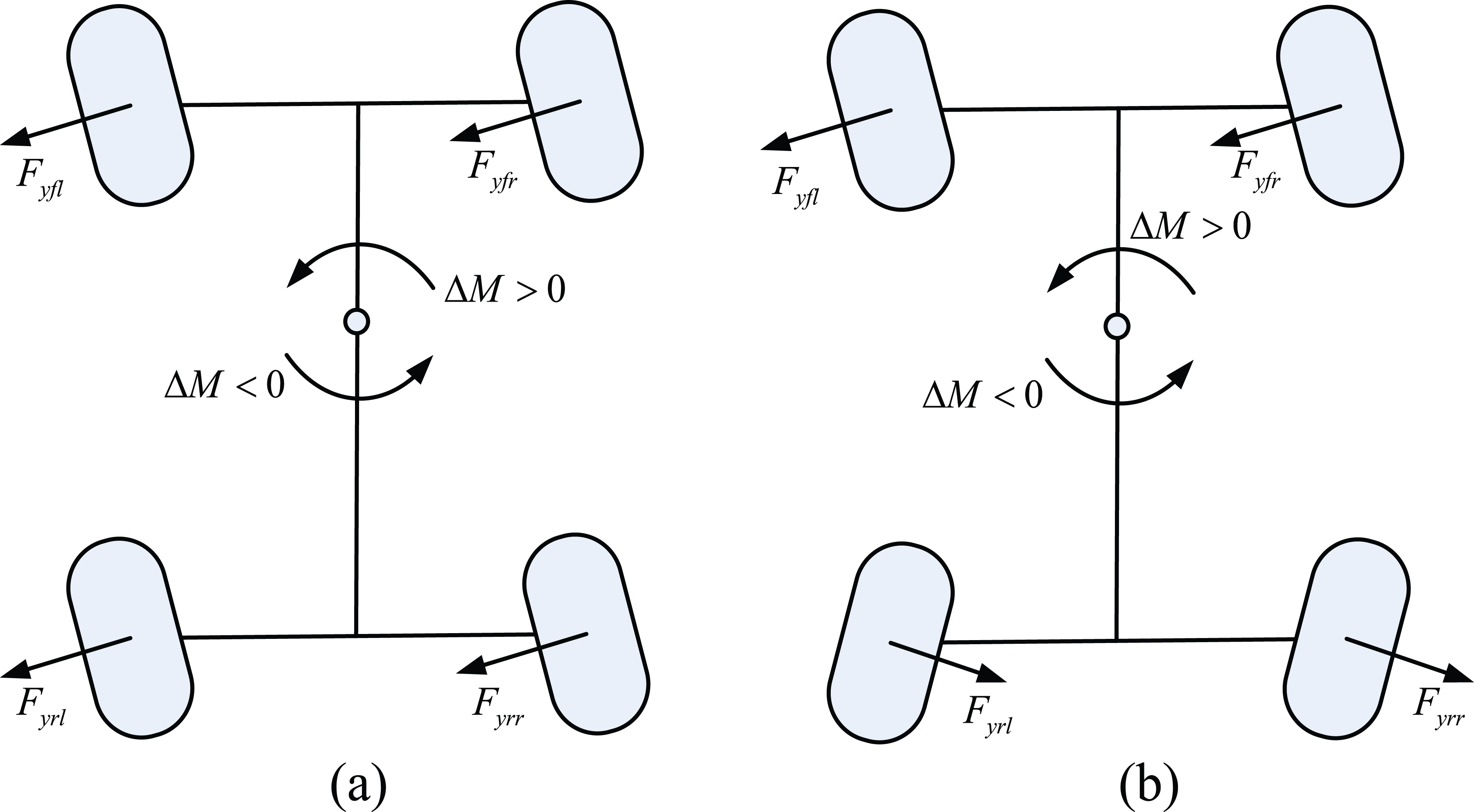
In this article, the counterclockwise direction is a positive direction. Figure 3 shows the trajectory when a vehicle is steered by a single wheel under the same speed (
Conclusion I: when a vehicle is steered by positive front wheel steering angle, it produces a positive yaw rate. When a vehicle is steered by positive rear wheel steering angle, it produces a negative yaw rate.
Conclusion II: in the same wheel steering angle condition, the outside wheel produces more yaw rate than the inside wheel. This is due to the fact that when vehicle steering, the wheel vertical load is transferred, which leads to the lateral force produced by the outside wheel more than that produced by the inside wheel.

Single wheel steering analysis.
Consider the fact that when vehicle speed is different, the rear wheel steering direction of 4WIS vehicle is different, as can be seen in Figure 4. Therefore, the given rear wheel steering angle adjusting rules must be different under different speed conditions. Take turn left, understeer, for instance. The yaw rate needs to be increased in this situation. At high speed, because the rear wheels are steered in the same direction as the front wheels, the control system should increase the front wheel steering angle and decrease the rear wheel steering angle. At low speed, because the rear wheels are steered in opposite direction of the front wheels, the control system should increase the front wheel steering angle and the rear wheel steering angle, simultaneously.
4WIS vehicle steering under different speed: (a) high speed and (b) low speed.
According to the above analysis and Conclusion I, the wheel steering angle adjustment rules of front and rear axle and the corresponding adjustment rules of parameter
Wheel steering angle adjustment rules of front and rear axle and corresponding control parameter adjustment rules.
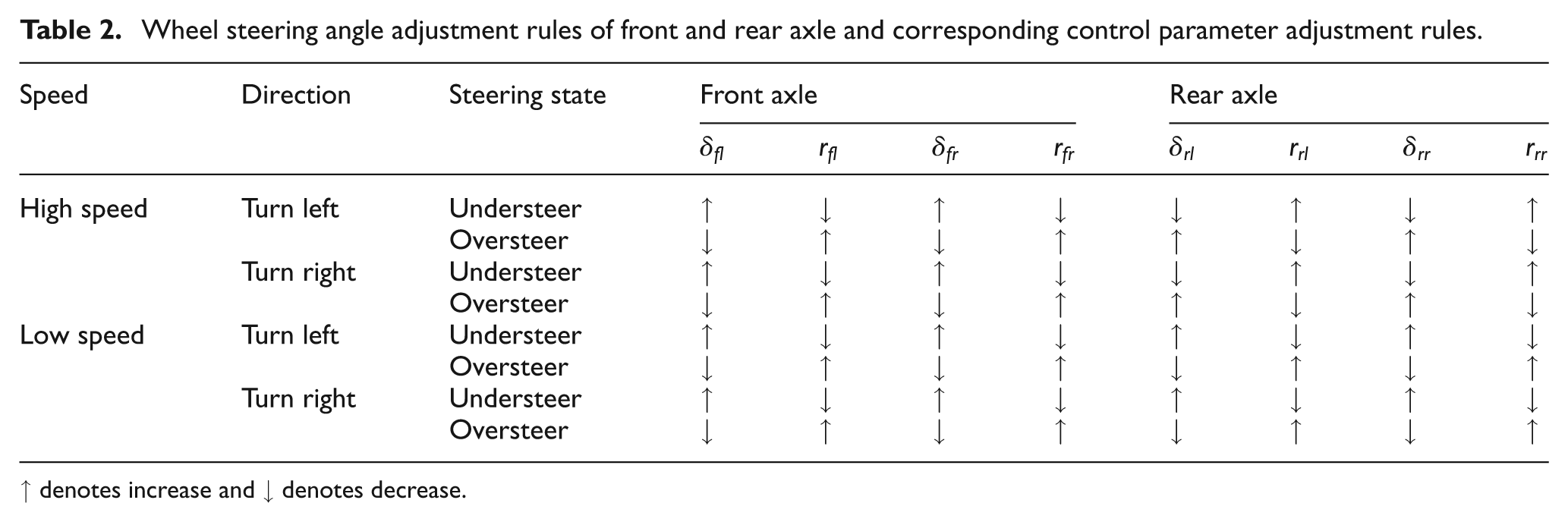
↑ denotes increase and ↓ denotes decrease.
Besides, in order to maximize the use of the adhesion between tire and road, improve the vehicle stability, and achieve four wheel independent steering, the wheel steering angle assignment rules among wheels and the corresponding restriction rules of parameter
Wheel steering angle assignment rules among wheels and corresponding control parameter restriction rules.

By combining Tables 2 and 3, the final adjustment rules of the control parameter

where
According to equation (25), the final adjustment rules of control parameter
Wheel steering angle adjustment rules of front and rear axle and corresponding control parameter adjustment rules.

Optimization of VLQR controller based on GA
GA is an influential tool for the solution of the complex optimization problems due to its advantages such as practicability, high efficiency, and robustness. Consequently, to improve the control performance, the proposed VLQR controller is optimized by GA in this article.26–28 GA includes some kinds of genetic operations such as code, mutation, crossover, and selection. The optimization process of the VLQR controller based on GA is shown in Figure 5.

GA optimization flow chart.
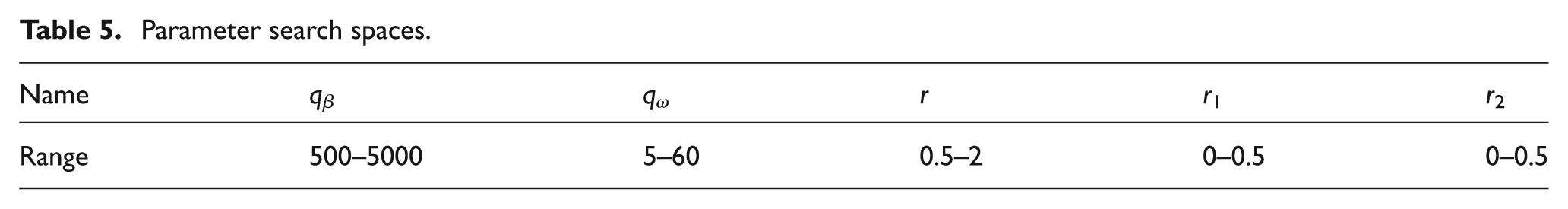
The optimized contents of GA are the base value and added value of the weighting matrix R and the weighting matrix Q. According to the above section, there are five parameters needed to be optimized:
Parameter search spaces.
The fitness value calculated from fitness function is the basic foundation of genetic operation. To improve the respond characteristics of the side slip angle and yaw rate, the sum of their integrated time absolute error (ITAE) criterion is selected as fitness function. It can be described as follows

The optimization goal of GA is to minimize the value of equation (26). Besides, the stochastic uniform selection method, the scattered crossover method, and the uniform mutation method are adopted in this article.
The vehicle stability under high-speed condition needs to pay more attention. Therefore, by using GA, the VLQR controller is optimized in high-speed and step input conditions. In the optimization process, vehicle speed is set to 120 km/h and the step signal of desired vehicle model front wheel steering angle is 0.05 rad. The population size is set to 20. The maximum number of generations is 20. The number of elite is set to 2. The crossover probability and mutation probability are set to 0.8 and 0.01, respectively. The optimized control parameters are shown in Table 6.
Optimal results.

Simulations
As the 8-DOF 4WIS vehicle dynamics model can simulate the vehicle response more accurately, the effectiveness and robustness of the proposed VLQR controller are verified by combining with the 8-DOF 4WIS vehicle model. The main vehicle parameters are shown as follows:
To verify the effectiveness and robustness of the proposed controller, four simulation experiments are conducted: (1) the comparison between the fixed parameter LQR (FLQR) controller and the VLQR controller, (2) the comparison between the optimized VLQR (GA-VLQR) controller and non-optimized VLQR controller, (3) the comparison between the GA-VLQR controller and the traditional 4WS controller, and (4) vehicle stability under cross-wind disturbance.
Comparison between FLQR controller and VLQR controller
The FLQR controller and the VLQR controller are compared to verify the effectiveness of the proposed control parameters adjustment strategy. The sinusoidal response experiment is chosen in this part. In the simulation, the input signal of front wheel steering angle of desired vehicle model is a sinusoidal signal whose amplitude is 0.05 rad and the frequency is 0.25 Hz. The initial vehicle velocities are 20 and 120 km/h, respectively. And the tire-road adhesion coefficient is set to 0.8 here.
To eliminate the interference from other factors and analyze the proposed control parameters’ adjustment strategy only, the parameters of both the FLQR controller and the VLQR controller are set to
At low speed, the errors between the actual vehicle state and desired vehicle state (including the side slip angle error

Comparison between FLQR controller and VLQR controller: (a) side slip angle error at low speed, (b) yaw rate error at low speed, (c) side slip angle error at high speed, and (d) yaw rate error at high speed.
Comparison between VLQR controller and GA-VLQR controller
The VLQR controller and the GA-VLQR controller are compared to verify the optimization effect of GA. The parameters of GA-VLQR controller are set as shown in Table 6; the parameters of VLQR controller are the same values as those described in the previous section, and they are both adjusted according to Table 4. The step response experiment is chosen in this part. In the simulation, the input signal of front wheel steering angle of desired vehicle model is a step signal whose value is 0.05 rad. The initial vehicle velocities are 20 and 120 km/h, respectively. And the tire-road adhesion coefficient is set to 0.8 here. The simulation results are shown in Figure 7.

Comparison between VLQR controller and GA-VLQR controller: (a) side slip angle at low speed, (b) yaw rate at low speed, (c) side slip angle at high speed, and (d) yaw rate at high speed.
As can be seen in Figure 7, both at low speed and high speed, the GA-VLQR controller has better performance. After optimization by GA, the errors between the actual vehicle state and desired vehicle state significantly reduce; this improves the vehicle stability effectively.
Comparison between GA-VLQR controller and traditional 4WS controller
The proposed 4WIS GA-VLQR controller, the traditional 4WS controller, and FWS system are compared and analyzed in this part. The control law of the traditional 4WS controller can be described as 29

The fishhook maneuver and the single lane change maneuver are performed in this part. The input front wheel steering angle signals of the desired vehicle model are shown in Figure 8(a) and (b). The initial vehicle velocity is 120 km/h. And the tire-road adhesion coefficient is set to 0.25 here. Figure 9(a) and (b) shows the vehicle responses under different control strategies in the condition of fishhook maneuver, and Figure 9(c) and (d) depicts the vehicle performances in single lane change maneuver condition.

Desired vehicle model input signals: (a) fishhook maneuver and (b) single lane change maneuver.

Fishhook maneuver and single lane change maneuver response curves: (a) side slip angle in fishhook maneuver condition, (b) yaw rate in fishhook maneuver condition, (c) side slip angle in single lane change maneuver condition, and (d) yaw rate in single lane change maneuver condition.
As can be seen in Figure 9(a) and (c), both the single lane change maneuver and the fishhook maneuver, the side slip angle under the control of the proposed 4WIS GA-VLQR controller almost remains at zero, and much less than that under the control of 4WS controller and FWS system. This greatly ensures the handling stability and steering safety of vehicle in high-speed and low adhesion conditions. Figure 9(b) and (d) shows that under the conditions of high speed and low adhesion, the yaw rate under the control of the proposed 4WIS GA-VLQR controller can still track the desired value effectively. In contrast, the yaw rate under the control of the 4WS controller obviously lags and has greater overshoot and longer settling time. The yaw rate under the control of the FWS system varies dramatically, and it shows that vehicle state may become unstable.
The robustness of the GA-VLQR controller under cross-wind disturbance
With the continuous improvement of vehicle speed, the vehicle stability under cross-wind disturbance must be taken into account in the research of vehicle active safety. Therefore, the robustness of the proposed controller under cross-wind disturbance is necessary to simulate and analyze. It is assumed that the cross-wind force acts on the right surface of vehicle vertically. The height of the cross-wind force acting point is the same as that of roll axis. The distance between the cross-wind force acting point and vehicle mass center is 0.2 m. In simulation, the vehicle runs on a straight way without driver intervention. The initial vehicle velocity is 120 km/h, and the tire-road adhesion coefficient is set to 0.25. At time 2 s, vehicle experiences cross-wind with a speed of 90 km/h and the cross-wind lasts 3 s, as shown in Figure 10(a).

Vehicle response curves: (a) cross-wind speed, (b) vehicle track, (c) side slip angle, and (d) yaw rate.
The simulation results under cross-wind disturbance are shown as Figure 10(b)–(d). Figure 10(c) and (d) shows that the vehicle responses vary from the desired values due to the effect of strong cross-wind. However, the vehicle response errors under the control of the GA-VLQR controller are less than that under the control of FWS system, especially the yaw rate error. As can be seen from Figure 10(b), without driver intervention, the FWS vehicle drifts off lane pretty soon and its lateral deviation reaches 13.63 m. In contrast, the lateral deviation of 4WIS vehicle under the control of the GA-VLQR controller is only 0.68 m. It shows that the proposed GA-VLQR controller has strong robustness and good capability of preventing lateral disturbance to ensure the vehicle driving safety.
Conclusion
In this article, a 4WIS vehicle VLQR control system optimized by GA is proposed. The proposed control system includes an LQR controller based on model following and a parameter adjuster based on vehicle steering state. By combining with the 8-DOF 4WIS vehicle dynamics model, the control system is simulated and analyzed. According to the simulation results, some conclusions can be drawn as follows:
The proposed LQR control parameter adjustment strategy based on vehicle steering state can reduce the vehicle response error effectively, which improve the adaptability and performance of the control system.
After optimization by GA, the VLQR control system provides a better performance, and the vehicle stability is further improved.
Compared with the FWS system and the traditional 4WS system, the designed 4WIS vehicle GA-VLQR control system can better ensure the vehicle steering safety in extreme condition (high speed and low adhesion).
The proposed GA-VLQR control system has strong robustness and good capability of preventing lateral disturbance. The handling stability and the steering safety can be guaranteed even under strong disturbance and without driver intervention conditions.
In conclusion, the proposed GA-VLQR control method is an effective method to control the steering motion of 4WIS vehicle, which can greatly improve stability and ensure safety.
Footnotes
Academic Editor: Xiaobei Jiang
Declaration of conflicting interests
The author(s) declared no potential conflicts of interest with respect to the research, authorship, and/or publication of this article.
Funding
The author(s) disclosed receipt of the following financial support for the research, authorship, and/or publication of this article: This research was supported by the International Cooperation Projects of Jilin Science and Technology Department (20130413056GH), the Science Fund of State Key Laboratory of Automotive Safety and Energy under Grant No. KF14182, Key Science and Technology Program of Changchun City Technology Bureau (2013021-13KG05), and National Distinguished Young Scholar Foundation Candidate Cultivation Program of Jilin University.