
Abstract
A four-wheel-independent-driving and four-wheel-independent-steering control and coordination system is proposed by combining a four-wheel-independent-steering control system and a four-wheel-independent-driving control system. The four-wheel-independent-steering control system includes a linear quadratic regulator controller that calculates four-wheel steering angles and a fuzzy logic parameter adjustor that adjusts the linear quadratic regulator control parameters based on the vehicle steering states. The four-wheel-independent-driving control system consists of three parts: a proportional–integral–derivative controller for tracking the desired vehicle speed, a sliding mode control controller, and its corresponding torque distributor for power-assisted steering. It is particularly necessary to point out that the sliding mode control controller only works when the activation condition is satisfied and the torque distribution strategy is developed on the basis of the four-wheel-independent-steering control system. Simulation studies have been conducted to evaluate the proposed system. The results show that the proposed system can improve handling stability of four-wheel-independent-driving–four-wheel-independent-steering vehicle effectively and have a strong robustness for driving on a mu-split road.
Keywords
Introduction
With the rapid increase in the amount of vehicles as well as the improvement in vehicle speed, driving safety has become a concern for many people, especially under high-speed condition. Several vehicle dynamics control (VDC) technologies such as anti-lock braking system (ABS),1,2 active rear wheel steer (ARS),3,4 four-wheel steering (4WS),5–7 and direct yaw-moment control (DYC)8,9 have been undergoing fast development in recent years. The purpose of these systems is to improve vehicle power and handling stability by controlling the torque or steering angle of the wheel. Due to strong couplings between vehicle dynamics characteristics, an individual system may have undesirable effects on others when it operates. Therefore, with the increasing number and complexities of electronic control systems in modem vehicles, considering the coordination of all the vehicle dynamics systems has emerged as one of the major issues faced by researchers.
To date, there have been some studies for the coordination of different vehicle dynamics systems. A Goodarzi and E Esmailzadeh, 10 J Kang et al., 11 and D Kim et al. 12 conducted in-depth study of vehicle longitudinal dynamics and put forward their own VDC systems. Based on multi-wheel independent driving/braking, the VDC systems they designed could control the vehicle yaw moment by differential driving/braking torque and provide both the desired longitudinal force and yaw moment, and then improve driving safety and handling stability of the vehicle. However, the effect of the lateral force on the longitudinal force was not taken into account in the VDC system designing process. From the dynamic integrated control perspective, B Mashadi and M Majidi, 13 M Naraghi et al., 14 and J Wang and RG Longoria 15 took into account the vehicle longitudinal dynamics and lateral dynamics and proposed the integrated chassis control system. The hierarchical control method was used in the designing of these integrated chassis control systems. The upper level controller computed the desired longitudinal/lateral forces and yaw moment to track the ideal vehicle dynamics states. The lower level controller was designed to distribute the desired longitudinal/lateral forces and yaw moment to each wheel. The coupling relationship between longitudinal dynamics and lateral dynamics was fully considered in the integrated chassis control system. However, the unified distribution of the total forces and yaw moment might cause frequent driving/braking system response, which could lead to the tires badly wear and serious energy wastage. J Song 16 and R Karbalaei et al. 17 attempted to solve the problem of coordinating all the vehicle dynamics systems in another way. In their researches, the coordination controller was designed using the decentralized control method, which could make the existing vehicle dynamics systems coordinate with each other.
Electric vehicle has advantages in sectors such as energy efficiency and VDC system designing.18–21 This article focuses on the research of the control and coordination for four-wheel-independent-driving (4WID) and four-wheel-independent-steering (4WIS) electric vehicle. The 4WID–4WIS electric vehicle is equipped with four in-wheel motors and four steering motors, which can achieve independent control of the torque and steering angle of each wheel. A 4WIS control system that includes a linear quadratic regulator (LQR) controller and a fuzzy logic parameter adjuster is put forward first. The LQR controller of 4WIS system is designed for tracking the ideal vehicle steering states’ purpose. Using the relationship between the LQR control parameters and the wheel steering angles, an LQR control parameter adjust strategy based on different vehicle steering states is proposed, and the corresponding fuzzy logic parameter adjuster is designed. Then, based on the 4WIS control system, a 4WID control system that includes a sliding mode control (SMC) controller, a torque distributor, and a proportional–integral–derivative (PID) controller is also put forward. To overcome the limitation of the 4WIS system in the situation of the lateral forces’ saturation, the 4WID control system not only has a PID controller for maintaining the desired vehicle speed but also there are an SMC controller and its corresponding torque distributor for power-assisted steering purpose. The SMC controller works when the activation condition is satisfied. Finally, the effectiveness and robustness of the proposed 4WID–4WIS control and coordination system are verified through several simulations.
System modeling for simulation
In this article, a nonlinear 8-degree-of-freedom (DOF) vehicle dynamics model with the G Gim and PE Nikravesh22,23tire model developed in the author’s previous study
24
is used for simulation. The 8-DOF vehicle model includes the longitudinal motion, the lateral motion, the yaw motion, the roll motion, and the rotational motion of four wheels. Besides, the models of the in-wheel motor systems and steering motor systems are added in the article. As can be seen in Figure 1, the inputs of the vehicle system model include the steering angle

System model for simulation.
In the motor modeling process, the motors and its controllers are considered as a whole by ignoring the complicated electromagnetic process. The motor controllers are responsible for driving the motors to make the actual outputs (
To fully analyze the performance of the 4WID–4WIS vehicle control system, a driver model based on yaw angle tracking (YAT) is proposed, which is used for the closed-loop simulation test of the vehicle control system.
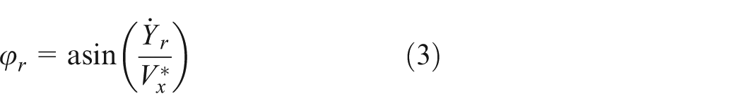
Figure 2 shows the schematic of YAT driver model geometry. In the YAT driver model, the road is regarded as an ideal “vehicle” with the desired speed

where
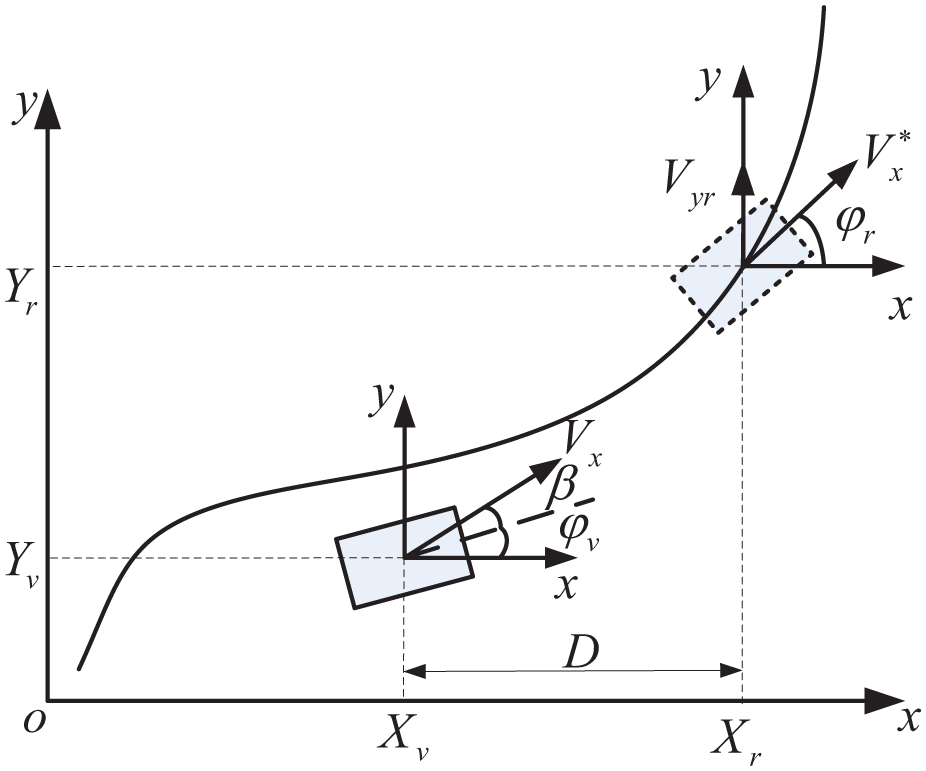
Schematic of YAT driver model geometry.
The YAT driver model calculates the desired vehicle model (more on this later) front-wheel steering (FWS) angle (
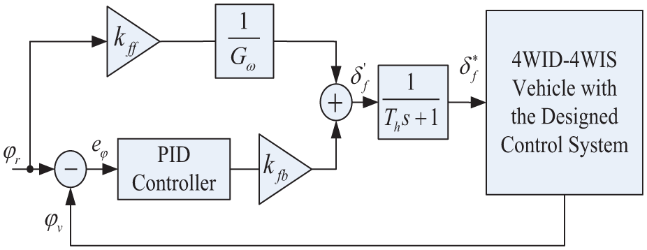
Structure diagram of the YAT driver model.
As can be seen from Figure 3, the YAT driver model is based on feedforward and PID control, and the expression of it can be written as

where

where
Furthermore, it is set that the ideal vehicle is always ahead of the 4WID–4WIS vehicle, and the distance between them is D. D is a function of the desired speed, which is defined as

where
Structure of 4WID–4WIS control and coordination system
The structure of the proposed 4WID–4WIS control and coordination system can be seen in Figure 4. As can be seen from Figure 4, the proposed system includes the desired vehicle model, the 4WIS control system, and the 4WID control system.

Structure of the proposed 4WID–4WIS control and coordination system.
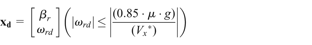
The desired vehicle model used in the control system designing calculates the ideal vehicle dynamics states, the outputs of which includes the ideal vehicle side slip angle and yaw rate. Specifically, the ideal yaw rate determined by linear 2-DOF vehicle model can be expressed as 26

where
The ideal side slip angle is set to 0 here. Modeled after equation (6), it can be expressed as

where
Transforming equations (6) and (7) into state-space representation, it can be given as

where


The 4WIS control system which controls the steering motion of 4WIS vehicle and aims to improve vehicle handling stability includes an LQR controller and a fuzzy logic parameter adjuster. The LQR controller tracks the desired vehicle model by controlling the steering angles of four wheels. The fuzzy logic parameter adjuster adjusts the LQR control parameters automatically on the basis of the vehicle steering state.
The 4WID control system is mainly responsible for tracking the desired vehicle speed and providing the additional power to help the vehicle steering motion. It consists of three parts: a PID controller, an SMC controller, and a torque distributor. The PID controller calculates the required wheel torque for tracking the desired vehicle speed. The SMC controller generates the additional yaw moment for power-assisted steering purpose. Then, according to the pre-defined rules, the additional yaw moment is converted into the additional driving/braking torque distributed to each wheel by the torque distributor. In addition, the SMC controller only works when the activation condition is satisfied.
Design of the 4WIS control system
LQR control
In this part, the LQR controller for modeling the following purpose is designed. A 2-DOF 4WIS vehicle dynamics model needed by the LQR controller designing is established first. Taking the wheel steering angles


where m is the vehicle total mass; a and b are the distances from vehicle’s center gravity to front/rear axle, respectively; Iz is the moment of inertia about yaw axis; Vx is the vehicle speed;
Transforming equation (9) and (10) into state-space representation, it can be given as

where state variables


Using the desired vehicle model and the 2-DOF vehicle model, the tracking error of the LQR controller is defined, as given by

where
Based on the linear quadratic optimal control theory, from equations (8), (11), and (12), the LQR control law can be described as follows (for more details, see Gao et al. 24 )
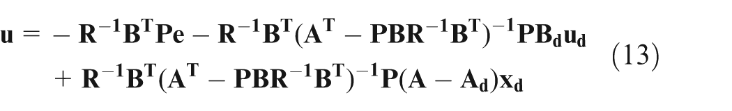
where

where
Fuzzy logic parameter adjuster
In the author’s previous study, it is shown that the control parameters
Adjustments of four-wheel steering angles.

Adjustments of control parameters.
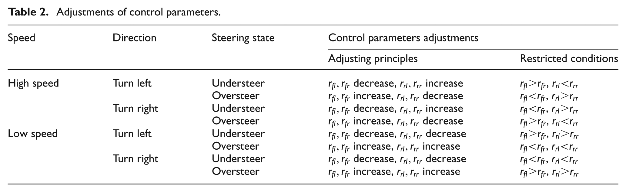
The incremental/decremental approach is used to adjust the control parameters in Gao et al.
24
However, this approach leads to a response fluctuation in a narrow range due to the control parameter jump caused by the changing of the vehicle steering states. To overcome this shortcoming, a fuzzy logic control parameter adjuster is designed according to Table 2. The inputs of the designed fuzzy logic control parameter adjuster are the vehicle speed
The input variable

Membership functions of input/output variables.
Based on the adjusting rules shown in Table 2 and the simulation results, a fuzzy rule base including 16 fuzzy rules is established, as can be seen in Table 3. The max–min method is used for fuzzy reasoning, and the center of gravity method is used for defuzzification in the article. The LQR controller and the fuzzy logic control parameter adjuster are integrated into one to form the complete 4WIS control system so as to control the steering motion of 4WIS vehicle and improve the steering safety.
Fuzzy control rule.

Design of the 4WID control system
It is well known that the 4WIS system has a distinct advantage in aspects of improving vehicle handling stability. However, when the lateral tire force is close to the saturation point, the 4WIS system has little or no effect on the vehicle stability improvement. To overcome this shortcoming, a 4WID control system with the power-assisted steering function is also designed in the study. The designed 4WID control system consists of three parts: an SMC controller, a PID controller, and a torque distributor.
SMC power-assisted steering controller
The SMC controller is regarded as the key component of the vehicle steering ancillary system, the main work of which is providing the additional yaw moment. Based on the theory of SMC, the sliding surface is defined as follows

where c is the parameter of the SMC controller.
Taking time derivative of

Equation (10) is rewritten as

where M denotes the additional yaw moment.
To make the system reach the sliding surface quickly and effectively, the sliding mode reaching law is applied to the design of the SMC controller. The exponential approach law is used in the article, and the symbolic function is replaced by the saturation function to reduce the system chattering.27,28 Thus

where
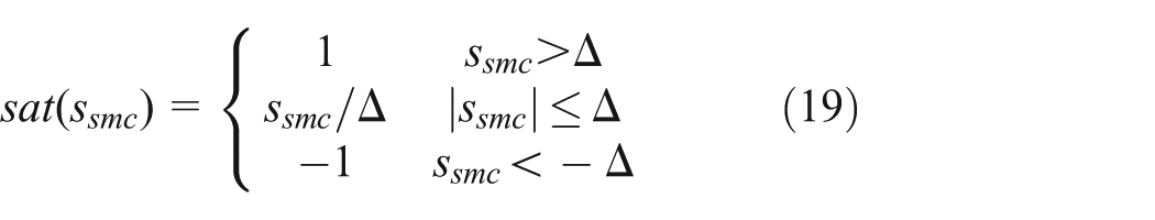
where
Substituting equation (17) into equation (18), the control law of the SMC controller is obtained as

The SMC controller uses the longitudinal tire forces to achieve the function of power-assisted steering, which may cause tire wear and energy wastage, if the controller acts frequently. To solve this problem mentioned above, an activation function determined by the vehicle speed and the yaw rate error is designed. The SMC controller only works when the activation condition is satisfied.
The activation function can be described as

where, as shown in Figure 6, the expressions of

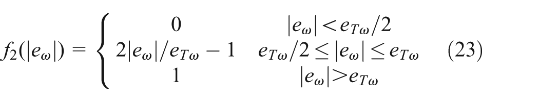
where

Activation function.
So the additional yaw moment can be revised as

Torque distributor
The additional yaw moment calculated by the SMC controller is distributed to each wheel through the torque distributor. Due to the effects caused by the SMC power-assisted steering system on the vehicle speed tracking system and the 4WIS system, two rules should be followed in the process of the torque distributor design; those are as follows:
No effect on the vehicle speed tracking;
No effect on the function of 4WIS system.
For the first issue, the distribution method of the same torque but in opposite direction is adopted for each side wheel. With this distribution method, the sum of the longitudinal tire forces remains the same without considering the wheel load transfer. So the vehicle speed tracking is not affected. For instance, in the turn left and understeer conditions, assuming that the additional yaw moment is distributed to the wheels in rear axle, it can be obtained as

where
For the second issue, because the SMC controller only works in certain conditions, the 4WIS system is given priority. Some situations in which the 4WIS system and the SMC power-assisted steering system work together are analyzed in the article. Taking high speed, turn left, understeer, for example, according to the adjusting rules of the wheel steering angles (shown in Table 1), the FWS angles need to be increased and the rear-wheel steering angles need to be decreased in this situation. Based on the friction ellipse principle, an increase in the longitudinal tire force (including driving force and braking force) causes a reduction in the lateral tire force, as shown in Figure 7. To ensure that the function of the 4WIS system is not affected, the rear wheels are chosen as the distributed objects of the additional yaw moment. In the same way, the distribution rules of the other situations can be designed. By the comprehensive analysis above, finally the rules for torque distribution are shown in Table 4.

Friction ellipse principle of tire forces.
Torque distribution rules.
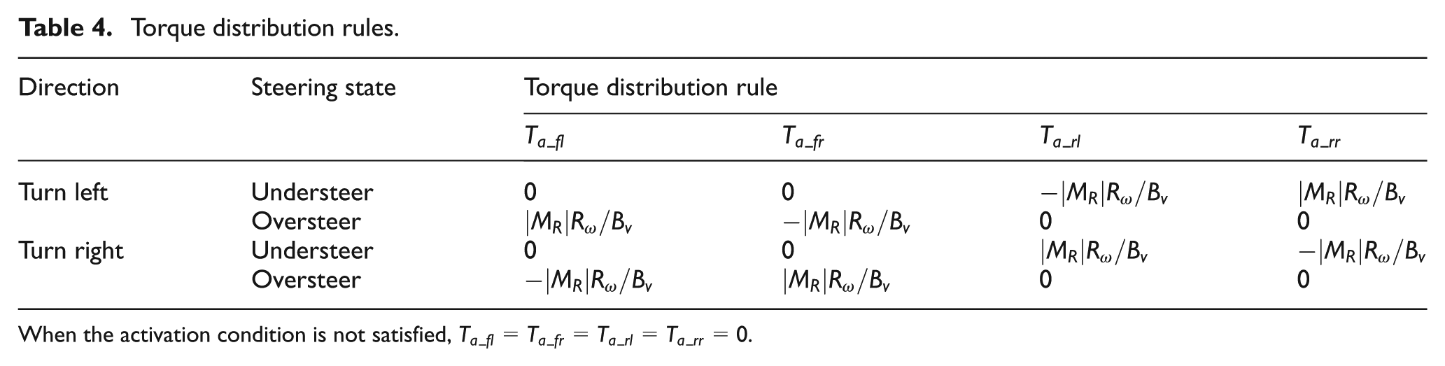
When the activation condition is not satisfied,
PID vehicle speed tracking controller
In this article, a simple PID controller is chosen as the vehicle speed tracking controller to calculate the required wheel torque for tracking the desired vehicle speed. The control low of the PID vehicle speed tracking controller can be expressed as
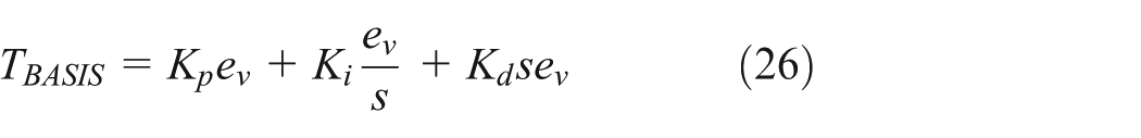
where
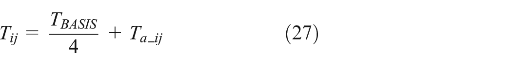
The calculated torque
Simulations
The 8-DOF vehicle dynamics model and the YAT driver model developed in the above part are used here for testing the effectiveness and robustness of the proposed 4WID–4WIS control and coordination system. The main vehicle parameters are shown in Table 5. In this part, the simulation experiments include open-loop simulation, closed-loop simulation, and hard braking simulation on a mu-split road surface.
Main vehicle parameters’ values.

Open-loop simulation
In this part, the step response experiment and the sinusoidal response experiment are chosen to analyze the designed 4WID–4WIS control and coordination system with different maneuvers. The desired vehicle speed is 33.3 m/s (approximately 120 km/h) here.
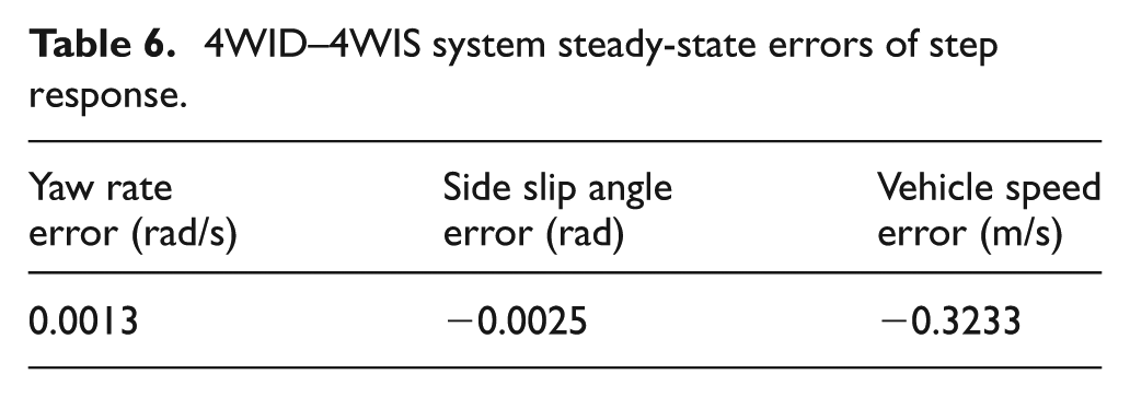
In the step response experiment, the input FWS angle of the desired model is a step signal whose value is 0.1 rad (approximately 5.7°), and the tire–road adhesion coefficient is set to 0.4. Figure 8 shows the results of the step response experiment under the control of the FWS system and the 4WID–4WIS control and coordination system. As can be seen from Figure 8(a) and (b), under the conditions of high speed and low tire–road adhesion coefficient, the 4WID–4WIS control and coordination system can still make the vehicle track the desired yaw rate preferably and keep the vehicle side slip angle small. In contrast, FWS vehicle is out of control. Furthermore, Figure 8(c) shows that compared with FWS system, the 4WID–4WIS control and coordination system has a smaller impact on vehicle speed. Under the control of 4WID–4WIS system, the errors between the stable response values and the desired values are shown in Table 6.
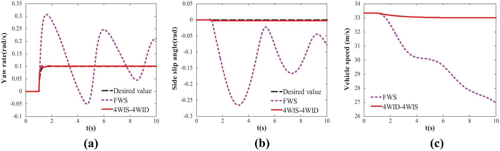
Step signal response with high speed on low tire–road adhesion coefficient road: (a) yaw rate response for step signal,(b) side slip angle response for step signal, and (c) vehicle speed response for step signal.
4WID–4WIS system steady-state errors of step response.
In the sinusoidal response experiment, the desired model FWS angle is a sinusoidal signal whose amplitude is 0.06 rad (approximately 3.4°) and frequency is 0.25 Hz. The tire–road adhesion coefficient is set to 0.8. The results of sinusoidal response experiment under the control of the FWS system and the proposed 4WID–4WIS control system are shown in Figure 9. As can be seen from Figure 9, in the high-speed, high tire–road adhesion coefficient conditions, the yaw rate under the control of the designed 4WID–4WIS control system is close to the desired value, so are the side slip angle and the vehicle speed. In contrast, FWS vehicle has a large side slip angle and obvious reduction in vehicle speed. Besides that, the yaw rate of FWS vehicle has a certain lag and a nonlinear relationship with the input FWS angle.

Sinusoidal signal response with high speed on high tire–road adhesion coefficient road: (a) yaw rate response for sinusoidal signal, (b) side slip angle response for sinusoidal signal, and (c) vehicle speed response for sinusoidal signal.
Figure 10 shows the comparisons between the 4WID control system, the 4WIS control system, and the 4WID–4WIS control, and coordination system in the article. From Figure 10, it is evident that the comprehensive control effect of the 4WID–4WIS control and coordination system is better than that of the 4WID control system and the 4WIS control system. The 4WID–4WIS control system is not as effective as the 4WID control system in vehicle speed remaining, but it takes out a better effect on tracking the desired yaw rate and side slip angle.

Step signal response errors: (a) yaw rate error, (b) side slip angle error, and (c) vehicle speed error.
Closed-loop simulation
To analyze the effectiveness of the proposed control system under the “driver–vehicle–road” closed-loop system, double-lane-change (DLC) maneuver experiment is performed with the help of the YAT driver model in this part. The desired vehicle speed is 25 m/s (approximately 90 km/h), and the tire–road adhesion coefficient is set to 1.0. The desired model FWS angle is calculated by the YAT driver model. Figure 11 shows the results of DLC experiment under the control of the FWS system and the 4WID–4WIS control and coordination system.

Results of DLC experiment: (a) yaw rate response for DLC, (b) side slip angle response for DLC, and (c) vehicle speed response for DLC.
The vehicle responses of the yaw rate and side slip angle in DLC experiment are shown in Figure 11(a) and (b). As can be seen in Figure 11(a) and (b), 4WID–4WIS vehicle with the proposed control system can track the desired yaw rate well while still remaining a relatively small side slip angle. Conversely, the traditional vehicle with FWS system has large tracking errors, especially the side slip angle. The maximum absolute of the side slip angle reaches 0.179 rad (approximately 10.3°). Figure 11(c) shows the DLC trajectories of the 4WID–4WIS vehicle and FWS vehicle. From the figure, it can be seen that the 4WID–4WIS vehicle with the proposed control system does a good job of completing the DLC tasks and has a small tracking error. Under the control of the same driver model, FWS vehicle does not complete the task. It not only exceeds the range prescribed by post but also drifts off the lane at the end of DLC.
Hard braking simulation on a mu-split road surface
In this part, the hard braking on a mu-split road surface is conducted to verify the robustness of the proposed 4WID–4WIS control and coordination system. In the simulation, the left-side wheels are on the low adhesion coefficient road, and the right-side ones are on the high adhesion coefficient road. The tire–road adhesion coefficients of each side are set to 0.2 and 1.0, respectively. The width of the lane is 3.5 m.
In the hard braking simulation, the initial vehicle speed is 35 m/s (approximately 144 km/h). Then, the vehicle reduces speed to 20 m/s in 3 s with a −0.5g deceleration. The simulation result is shown in Figure 12. As can be seen from the figure, when the emergency brake is applied on the mu-split road surface, FWS vehicle swiftly loses control and slides out of the lane (at 1.67 s). In contrast, the 4WID–4WIS vehicle deviates from the middle lane, but always keeps in the lane. This illustrates that the proposed 4WID–4WIS control and coordination system has strong robustness in condition of hard braking on a mu-split road surface.

Hard braking on a mu-split road surface.
Conclusion
In this article, the control and coordination strategy for 4WID–4WIS electric vehicle is studied and a 4WID–4WIS control and coordination system is proposed. To testify the effectiveness and robustness of the proposed 4WID–4WIS control and coordination system, some simulations have been done. The simulation results of the designed control system lead to the following conclusions:
Open-loop simulation experiments (step response experiment and sinusoidal response experiment) confirm that both on low adhesion coefficient road and on high adhesion coefficient road, the control effect of the 4WID–4WIS control and coordination system is much better than that of the FWS system. Under the control of the designed coordination system, the side slip angle almost remains at 0 and the yaw rate is so close to the desired value, which greatly improves handling stability and driving safety of 4WID–4WIS vehicle. Besides, compared with the 4WID control system and the 4WIS control system, the 4WID–4WIS control and coordination system has better comprehensive control effect.
Closed-loop simulation experiment (DLC experiment) shows that the proposed 4WID–4WIS control and coordination system can ensure its effectiveness in the driver–vehicle–road closed-loop condition.
The designed 4WID–4WIS control and coordination system provides a good robustness that ensures stability against split tire–road adhesion coefficient. Even hard braking on a mu-split road surface, the 4WID–4WIS coordination system can also ensure vehicle driving safety.
In conclusion, the proposed control and coordination strategy of the 4WID–4WIS vehicle is a potential method, which can effectively control the 4WID–4WIS vehicle, greatly improve handling stability, and ensure driving safety.
Footnotes
Academic Editor: Xiaobei Jiang
Declaration of conflicting interests
The author(s) declared no potential conflicts of interest with respect to the research, authorship, and/or publication of this article.
Funding
The author(s) disclosed receipt of the following financial support for the research, authorship, and/or publication of this article: This research was supported by the National Natural Science Foundation (no. 51575229), the Fundamental Research Funds for the Central Universities and State Key Research and Development Program of China (no. 2016YFB0100900), and the National Distinguished Young Scholar Foundation Candidate Cultivation Program of Jilin University.