
Abstract
An experimental investigation and performance analysis of inertia properties measurement for heavy truck cab is presented. This method is specifically intended for measuring the inertia properties of irregular rigid bodies, and it has the potential to be applied to the measurement of the inertia properties of vehicle bodies, such as the cab, engine, and gearbox. This article, based on CATARC moment of inertia measurement system test rig, develops an accurate measuring method to identify inertia parameters of heavy truck cab. First, corresponding tests are carried out, and the lever principle and moments of inertia parallel theorem are employed to calculate and analyse the test results, which leads to the accurate value of inertia parameters. Second, the performance analysis of the proposed method is verified through the measurement error analysis. As a result, the proposed method shows high accuracy, which provides an experimental basis for accurate inertia parameter measurement of heavy truck cab.
Introduction
Modern automobile technology used to isolate the vibration caused by vehicle powertrain or pothole in the road is usually elastic suspension system, which effectively reduces the vehicle vibration and noises and improves the ride comfort and vehicle performance quality. Consequently, the design and optimization analysis of heavy truck cab mounting and suspension system have been a tough issue and received constant concern in the modern vehicle development and research area. While the design of heavy truck cab mounting and suspension system includes more than mounting position, static and dynamic stiffnesses and damping parameter design, it is also closely related to the inertia parameters of heavy truck cab such as mass, the position of the centre of gravity (CG), moment of inertia (MOI) and the product of inertia. The application of the inertia parameter test rig enables the accurate measurement of inertia parameters and then it provides the basic parameters required in the establishment of heavy truck model and the design of heavy truck cab mounting and suspension system, so as to make a valid way for the heavy truck cab dynamic analysis and suspension system optimization design. This method makes it possible to identify the potential problems at an early stage and to make corresponding improvements, thus shortens the heavy truck development cycle and improves efficiency.
In recent studies, the methodologies used to measure the CG position and inertia tensor of heavy truck cab are usually divided into four categories: calculation method based on three-dimensional (3D) solid model,1,2 the weighing method, 3 modal test method4,5 and experimental test methods.6,7 It is a huge and difficult job to establish the 3D solid modelling of heavy truck cab, such as the seat, harness and internal and external decorations. Therefore, the accuracy of the model cannot be guaranteed. Hence, the calculation method based on the computer-aided design (CAD) model is not popularly used. The weighing method usually can only get the mass and the position of the CG parameters. For large volume and mass truck cab, the turnover manoeuvre is difficult for them during the test. The modal method is mainly used for components of powertrain, engine and other small assemblies. It is rarely used in complex structure, such as large heavy truck cab. The most reliable way to get accurate estimation of the inertia properties is via experimental tests. Among the inertia properties, only the mass can be indirectly measured with very high accuracy.8,9 The CG can be identified by complex test rigs. For example, Gobbi et al. 10 used the non-linear motion of multi-cable pendulum to measure the inertia properties of rigid bodies. A validation of the measurement procedure is performed by means of experimental tests. Almeida et al. 11 provided the group of modal methods, where the rigid body properties are estimated from a modal analysis identification procedure. Renato et al. 5 proposed an equipment and a procedure for the determination of large object inertia parameters. Measurement is based on the application of a least square optimization technique on data from force and displacement sensors on the test bench. The Anthony Best Dynamics (ABD) Limited company 12 develops the MOI test system. The MOI test system is capable of finding the position of the CG of the body, the mass and principal inertias and the orientation of the principal axes. In the latter case, better accuracy would be expected; however, the identification of the CG location is a direct operation only for the two coordinates in the horizontal plane. For the third coordinate, if the rigid bodies cannot be rotated at will, quite complicated approaches are needed, and poor measurement accuracy is to be expected. 13
Test hardware system
Moment of inertia measurement system test system
The moment of inertia measurement system (MIMS) is an enhancement to ABD’s suspension parameter measurement machine (SPMM), which extends the machine’s capability beyond its original kinematics and compliance (K&C) testing role. The MIMS is designed to measure the moments of inertia and CG position of rigid bodies. It is specifically intended for measuring the inertial properties of other rigid bodies, such as vehicle bodies, truck cabs and engines. The system is capable of finding the position of the CG of the body, the mass and principal inertias. The MIMS concept is shown in Figure 1.

MIMS system concept.
During these tests, the wheels must not be in contact with the ground. Clearly, it is possible to remove the wheels altogether to minimize the unspring mass. The body of the vehicle is clamped to the test base using the standard sill clamps used for K&C testing. These are mounted on the top of the multi-axis load platforms, so that all the forces transmitted from the base to the vehicle bodies are measured.
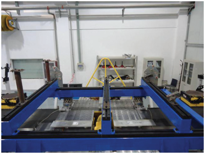
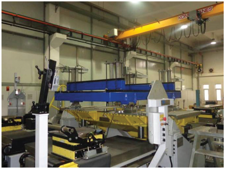
As illustrated in Figure 2, MIMS inertia parameter test system based on K&C test rig in CATARC, with four six-axis force clamps (see Figure 3), can attach the vehicle bodies to the test base of the test rig where six-axis motions can be carried out (X, Y, Z, roll, pitch and yaw). A series of test conditions are exerted by six electrical cylinders, and the relevant parameters can be figured out through calculating the data generated in the callipers. The excitation is pseudo-static for measurement of the CG height and is applied at 1 Hz (typically) for inertia measurements.

Moment of inertia measurement system (MIMS) test rig.

Moment of inertia six-axis force calliper.
Inertia parameter test system of heavy truck cab
As the heavy truck cab is composed of irregular and complex parts such as the seat and internal and external decorations, it is difficult to calculate the inertia parameters but makes it obtainable through the inertia parameter testing system. The proposed test system takes the heavy truck cab of specific vehicle as example, based on the inertia parameter MIMS test rig, through adjusting the joint angle and length of the test base and heavy truck cab (see Figure 4), and the heavy truck cab is mounted to the test base as in a real vehicle. As illustrated in Figure 5, the first step is to measure the MOI parameters of heavy truck cab and the test base; second step is to remove the heavy truck cab; however, as the connecting device is not part of heavy truck cab, it is left together with the test base, and the inertia parameters of only the test base are measured as illustrated in Figure 6. The test data collected above are put to analysis and then the CG position is identified, and the MOI of heavy truck cab can be figured out.

Heavy truck cab installation on the test base: (a) front installation method and (b) rear installation method.

Inertia parameter test system (heavy truck cab + the test base).
Inertia parameter test system (only the test base).
Identification procedure of the inertia properties
Coordinate system is established according to the right-hand rule, choosing the forward direction along the platform as the positive direction of X-axis, the direction to the left as the positive direction of Y-axis, the vertical upward direction as the positive direction of Z-axis and the origin coordinate point as the centre of symmetric point. The identification procedure of MIMS parameters is as follows:
Step 1. According to the inertia parameter test data (heavy truck cab and the base together) and measured data of only the base, the CG position of heavy truck cab can be identified. The calculating lever principle is shown as follows


where m is the mass of body of heavy truck cab and the base together; m1 is the mass of body of heavy truck cab; m2 is the mass of body of the base; x, y and z are the distances from the CG point of the body of heavy truck cab and the base together to the coordinate origin of the test rig along the three directions; x1, y1 and z1 are the distances from the CG point of body of heavy truck cab to the origin coordinate of test rig along the three directions; and x2, y2 and z2 are the distances from the CG point of body of the base to the origin coordinate of test rig along the three directions. From the above equations, the CG point position (x, y, z; heavy truck cab and the base together) relative to the coordinate origin of the test rig can be identified.
Step 2. According to the parallel axis theorem, the body of mass is made to rotate about an axis passing through the body’s centre of mass. The body (heavy truck cab and the base together) has a MOI J0 with respect to this axis. The parallel axis theorem states that if the body is made to rotate around a new axis which is parallel to the first axis and displaced from it by a distance d, then the MOI J with the new axis is related to J0 is

The products of inertia Jxy, Jxz and Jyz have the similar calculation as follows


where Jxy, Jxz and Jyz are the products of inertia of the body, and Jxy0, Jxz0 and Jyz0 are the products of inertia of the body which coordinate origin point and moves to position x1, y1 and z1.
Step 3. Working on the same principle, the parallel axis theorem is used to figure out the MOI of only the base body (products of inertia are included) in the test rig coordinate system.
Step 4. The MOI (products of inertia are included) obtained from step 2 is used to minus the MOI (products of inertia are included) obtained from step 3, and the result is the MOI of heavy truck cab (products of inertia are included) in the test rig coordinate system.
Step 5. The CG/MOI testing process takes less than 10 min.
Measurement results
Measurement results of mass and CG position
Based on the inertia parameter measuring test rig, the experimental case study is illustrated in Figure 7, with the corresponding location of the reference point. In the test rig measuring system, the multi-axis load cells used are piezoelectric devices manufactured by Kistler. Piezoelectric are used because of their unique ability to measure small forces accurately in the presence of the large static load generated by the weight of the vehicle bodies, such as heavy truck cab. The test excitation is pseudo-static for measurement of the CG height and is applied at 1 Hz (typically) for inertia parameter measurements. The measurement result of mass and CG position is shown in Table 1.

Reference point during the experimental test.
Experimental result of mass and CG position.
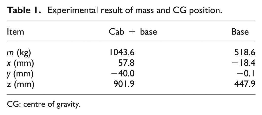
CG: centre of gravity.
Note that the midpoint of front two mounting hole connection line of heavy truck cab is chosen as the reference point as illustrated in Figure 7, which is marked by a red circle. The position of the reference point in the coordinate system of test rig is (863, 2.5, 756).
From Table 1, it is illustrated that the mass of heavy truck cab and the base is 1043.6 kg, and the CG is 57.8 mm forward from the test rig coordinate origin point, 57.8 mm to the right and 901.9 mm upwards. Simultaneously, the mass of only the base body is 518.6 kg, and the CG is 18.4 mm backwards from the test rig coordinate origin point, 0.1 mm to the right and 447.9 mm upwards.
Calculating based on the lever principle according the test data of mass and CG position, the mass and CG of heavy truck cab are listed in Table 2 choosing the reference point on the heavy truck cab to identify the CG position of heavy truck cab.
Experimental result of mass and CG position (heavy truck cab).
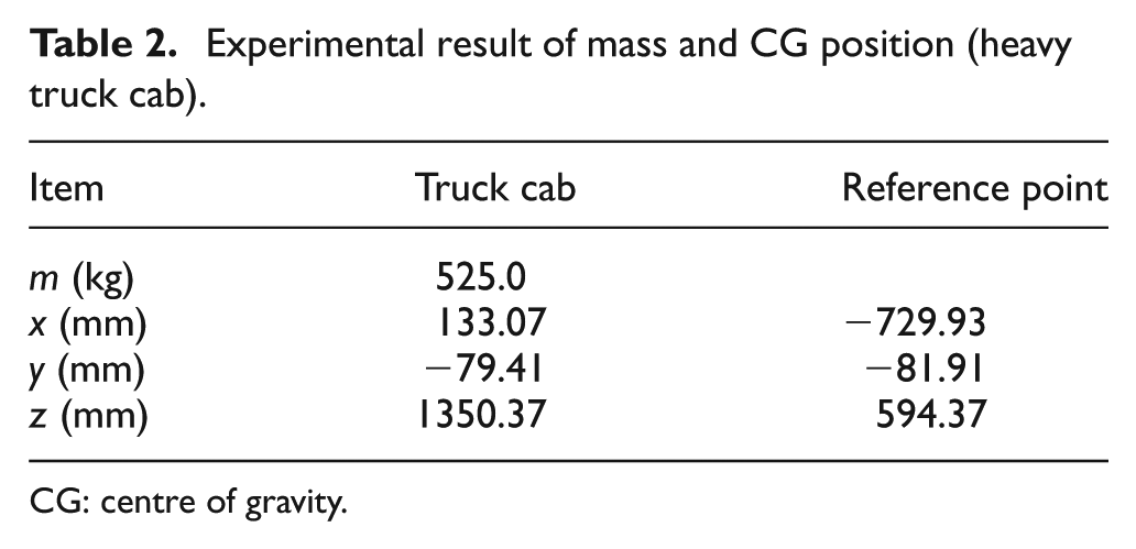
CG: centre of gravity.
From Table 2, the mass of heavy truck engine and the base minus the mass of the base equals the mass of heavy truck cab which is 525.0 kg, and the CG is 133.07 mm forward from the test rig origin coordinate point, 79.41 mm to the right and 1350.37 mm upwards.
Measurement results of inertia parameters
The experimental data by the inertia parameter measuring test rig are used in the identification of inertia parameters for heavy truck cab based on the parallel axis theorem. The identification results are shown in Table 3.
Identification results of inertia parameters.
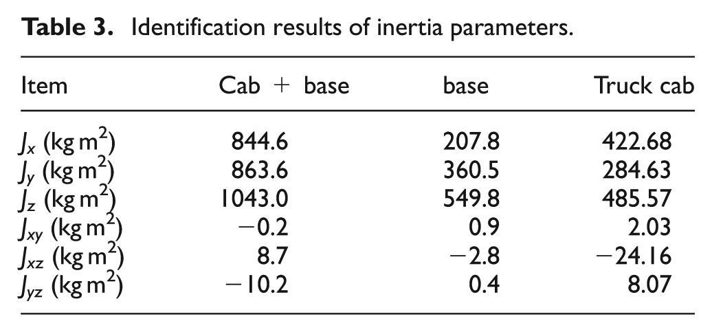
From Table 3, it is shown that heavy truck cab MOI is 422.68 kg m2 relative to X-axis, 284.63 kg m2 relative to Y-axis and 485.57 kg m2 relative to Z-axis. The three products of inertia Jxy, Jxz and Jyz are 2.03, −24.16 and 8.07 kg m2, respectively.
Error analysis
Error analysis means the difference between the true value and measurements. MIMS test rig has build-in standard specimen which has the true values of inertia parameters. This article analyses the differences of the standard specimen between true value and measurements, which can be used in measurement accuracy evaluation of inertia parameters.
Applying the same measuring method to measure the heavy truck cab inertia parameters to the indirect measurement of standard specimen, the test cases are shown in Figures 8 and 9 and then the inertia measured results are put to compare with the true values so as to get the accuracy evaluation. The error analysis is shown in Tables 4 and 5.

Inertia parameter measurement of standard specimen and the test base.
Inertia parameter measurement of the test base.
Comparisons between the true and the measured CG position and mass for the standard specimen.

CG: centre of gravity.
Comparisons between the true and the measured inertia parameters for the standard specimen.

Figure 8 shows that standard specimen and the base are clamped on the MIMS test rig to measure inertia properties. Figure 9 illustrates only the test base which is fixed on the MIMS test rig to measure the inertia parameters. The comparisons between the true and the measured CG position and mass for the standard specimen are illustrated in Table 4, and the comparisons between the true and the measured inertia tensor for the standard specimen are shown in Table 5.
As shown at the top of Table 4, the measured mass of standard specimen is 1153.5 kg, and its true mass is 1144.5 kg. As shown at the bottom of Table 4, the measured height of CG position is 483.62, and its true height is 483.73. It shows that the mass measurement absolute error is 9.04 kg, and the measurement relative error is only 0.79%. At the same time, the measurement absolute error of height of CG position is 0.09 mm, and the measurement relative error is only 0.019%.
Table 5 shows that the measurement relative errors of moments of inertia parameters are about 1%. Compared to the average relative error (3%) of other MIMS measurement equipment, the proposed MIMS test rig has a very high accuracy, especially in the measurement of the height of CG position.
The comparison results shown in Tables 4 and 5 indicate that the errors of the MIMS measurement system are quite subtle, which demonstrates the reliability and accuracy of the proposed inertia parameters and data processing procedure.
Conclusion
A new approach for the accurate measurement of the inertia parameters for heavy truck cab is presented. Compared to the conventional inertia parameter measurement method, this new approach has several advantages:
Using the ABD MIMS measuring instrument, the measurement accuracy is significantly enhanced;
The calibration procedure with standard specimen showed little deviation from conventionally true values, and the developed method showed good repeatability;
The MOI measurement system enables the CG coordinates and inertia tensor components to be measured for kinds of vehicle bodies such as powertrain, truck engine, gearbox and so on;
The CG/MOI testing process takes less than 10 min, so the test method has good working efficiency.
Footnotes
Academic Editor: Rahmi Guclu
Declaration of conflicting interests
The author(s) declared no potential conflicts of interest with respect to the research, authorship, and/or publication of this article.
Funding
The author(s) disclosed receipt of the following financial support for the research, authorship, and/or publication of this article: This work was financially supported by National Natural Science Foundation of China (51205105) and Natural Science Foundation of Hebei Province (E2012402014).