
Abstract
A brake hardware-in-the-loop simulation system for a railway vehicle provides an effective platform for testing the braking performance under various dangerous braking conditions. However, in general, four-brake calipers are required to implement a mechanical brake system for one car. In this article, we implement a brake hardware-in-the-loop simulation system only with one brake caliper and three air tanks accounting for hysteresis and pneumatic cylinder dynamics, ultimately saving installation space and reducing financial budget costs. Since the brake caliper has a high nonlinearity, such as hysteresis resulting from friction and from the precompressed spring of the brake cylinder, we measured the hysteresis of the brake caliper clamping force for a mechanical brake system using loadcells, based on which a mathematical model was constructed for the hysteresis of the clamping force between the brake pad and the disk. Moreover, the pneumatic cylinder dynamics are identified and are implemented in three air tanks, together with hysteresis nonlinearity. The proposed brake hardware-in-the-loop simulation system is applied to the wheel-slide protection simulation of a railway vehicle with an initial speed of 80 km/h and demonstrated experimentally accounting for the hysteresis and brake cylinder dynamics.
Keywords
Introduction
As railway vehicles become faster, running safety and ride comfort should be considered more seriously. Specifically, the wheel slide of a railway vehicle due to excessive braking forces could lead to a flat wheel that would result in poor braking performance and passenger discomfort. Sometimes a flat wheel could elicit dangerous situations such as derailments.
To prevent the wheel slide, a railway vehicle uses a wheel slide protection (WSP) device which releases braking force by exhausting compressed air to the atmosphere for re-adhesion when the wheel slide is detected. The WSP device is related to the safety and ride comfort and is crucially important in the braking system of a railway vehicle. However, the actual vehicle tests for WSP are limited by numerous constraints, such as safety, time, and cost. A good alternative to an actual railway vehicle test is the use of a hardware-in-the-loop simulation (HILS) brake system that includes actual mechanical brake hardware and a high-speed digital signal processing device for simulating train running dynamics. Using a brake HILS system, we can implement various braking schemes under severe conditions of a railway vehicle.
Maki et al. 1 and Watanabe et al. 2 developed a HILS system consisted of an actual car, a distributed real-time simulator, a real-time network, and car end simulators that simulate the dynamic behavior of the end surfaces of adjacent car bodies. Their work was mainly focused on accurately generating multicar dynamics using the MATLAB/Simulink software. Bosso et al. 3 proposed a design approach for real-time simulation based on a decomposition of the mechatronics system into groups with elements. They used Simpack and Simulink for simulations. Spiryagin et al. 4 investigated the usage of the model of the locomotive’s bogie test rig created using the GENSYS multibody software and analyzed the calculation time for each time step. Shin et al. 5 applied a magneto-rheological damper in order to improve the ride quality of a railway vehicle using a 1/5 scaled railway vehicle model.
Pugi et al. 6 and Meli et al. 7 implemented a multipurpose platform for hardware-in-the-loop (HIL) testing of the relevant railway subsystem’s safety using MATLAB/Simulink with a three-dimensional dynamic model, which was verified using automated dynamic analysis of mechanical systems (ADAMS) simulations. They computed the braking force by measuring the pneumatic pressure. However, in this way, nonlinearity of a caliper mechanism, for example, friction and hysteresis of the brake cylinder (BC) and leverage mechanism could not be considered completely.
Piechowiak8–10 improved a pneumatic model of a brake system, conducted research on frictional forces of BCs and brake leverage characteristics, and verified a pneumatic railway brake model, including the hysteresis of the brake caliper.
More recently, Allotta et al. 11 introduced a new adhesion model12 to increase the accuracy in reproducing degraded adhesion conditions due to adhesion recovery by cleaning effect at the contact surface of a railway vehicle. However, in this paper we use a conventional adhesion model 12 that has been well validated for last ten years.
We have developed a brake HILS system of a railway vehicle for WSP tests that has been used for several years.13–16 In general, it uses four-brake calipers to implement a mechanical brake system for each car, which requires a significant amount of space and a major budget allocation to account for the purchase of the four calipers.
In this article, we developed a HILS brake system with only one brake caliper and three air tanks (instead of four-brake calipers), which results in saving installation space and reducing the financial budget. However, the actual clamping force of the caliper measured directly by the loadcells and the computed clamping force from the pneumatic pressure measurement of air tanks were considerably different, and an investigation and compensation of these differences were thus needed. Since the brake caliper has a high nonlinearity, such as hysteresis, resulting from the friction and the precompressed spring of the BC, we needed to account for the effect of hysteresis as well as the pneumatic cylinder dynamics in the three air tank modules.
Previously, we measured the pneumatic pressure of the BC in order to compute the braking force acting on the wheel. However, in this article, we measured a braking force directly using loadcells installed between a brake pad and a wheel. That is, using loadcells, we measured the hysteresis of the brake caliper clamping force and then constructed a mathematical model for the hysteresis of the clamping force of the mechanical brake system.
Using the modeled hysteresis and identified cylinder dynamics, we realize the hysteresis effect and the cylinder dynamics effect on the air tank modules. The proposed brake HILS system is applied to the WSP simulation of a railway vehicle with an initial speed of 80 km/h, and the brake HILS is demonstrated experimentally, accounting for hysteresis and BC dynamics.
Description of a brake HILS system
We developed a brake HILS system that consists of one brake caliper and three air tanks for testing the mechanical brake performance of a railway vehicle. In this way, we can save installation space and reduce costs compared to a HILS system with four-brake calipers. The target vehicle was an intercity railway train in Korea with a maximum commercial speed of 180 km/h.
The brake HILS system was consisted of a wheel, two brake pads, a brake caliper, a brake operating unit (BOU), including an electronic control unit (ECU), four WSP valves, four air tanks, an air compressor, an air reservoir with a 300 L volume, a dSPACE device, three computers, three loadcells, six pressure sensors, air pipes, software, and signal interfacing wires. The hardware configuration of the HILS system satisfied the design requirements specified in Appendix H of the UIC Code 541-05. 17 Railway vehicle dynamics13,14 and the wheel–rail contact model were simulated using a dSPACE device with xPC Target and MATLAB/Simulink.12,15,16,18,19 The clamping forces of a mechanical brake were fed back to the railway vehicle dynamics, and the vehicle speed was then decreased using dynamic simulations. The ECU and WSP controllers were implemented using an industrial PC which communicated with a host PC with the xPC Target. The schematic block diagram and the actual picture of the brake HILS system are shown in Figure 1(a) and (b), respectively.

(a) Schematic block diagram and (b) photograph of the presently developed brake HILS system.
As shown in Figure 1, only the first module includes an actual brake caliper, while the other three modules have air tanks. The volume of an air tank was designed to be 2 L which is the estimated sum of the pipe volume and the BC volume of the actual train. The BC volume is 0.053 L and corresponds to approximately 3% of the total pipe volume. The first air tank, connected to a brake caliper, is filled with 367 stainless steel balls with 1.03 cm diameter in order to ensure that all four modules have the same pneumatic volume. Note that the other three modules do not have BCs.
The brake caliper used in the HILS system is a wheel-mounted type, as shown in Figure 2. The schematic of the brake caliper is shown in Figure 3, in which the input pressure of the BC actuated the lever and then squeezed the wheel disk. The piston inside the BC was preloaded. To measure the clamping force of the brake caliper, we installed three loadcells in the wheel disk between the train wheel and the disk pad, as shown in Figure 3. The positions of the loadcells were determined to match up the center of gravity of the three loadcells with the center of acting points of the brake pad.
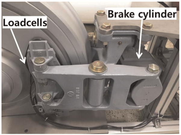
Photograph of the brake caliper installed in the HILS system.

Schematic structure of the brake caliper.
Figure 4 shows an actual WSP valve used in the brake HILS system. The WSP valve rapidly exhausts compressed air from the BC to the atmosphere when the wheel slide is detected to lie between the wheel and the rail.
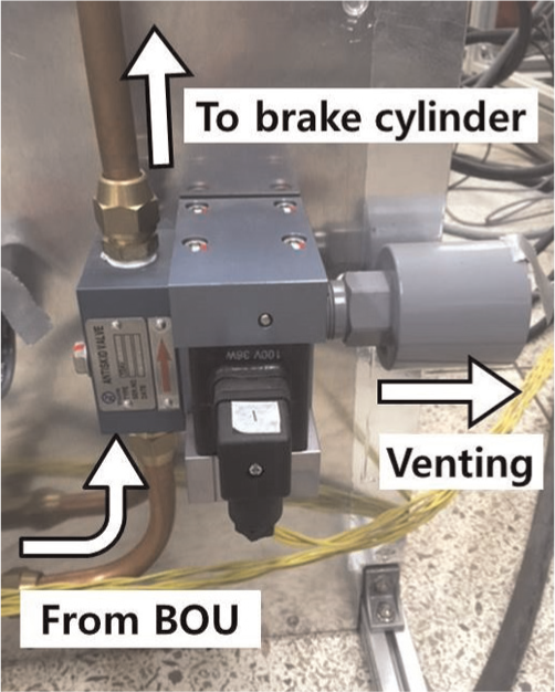
Photograph of the WSP valve installed in the HILS system.
An air compressor supplies compressed air at eight bars to the BOU through a 300-L air reservoir. The BOU of the HILS system then supplies compressed air to the BC by controlling the range of the pneumatic pressure from zero to a maximum pressure, in accordance with a braking command level.
The signal flow from the BOU to the clamping force generation is shown in Figure 5. Pressure is supplied pneumatically from the BOU to four air tanks through WSP valves. A brake caliper is connected to the first WSP valve, and the actual clamping force is measured using loadcells. The other three sets only have air tanks without calipers, and the clamping forces of these three sets are computed from the pressure measurements of the air tanks.

Signal flow from the BOU to the clamping force generation in the brake HILS system.
As the compressed air is transferred to a BC, the volume of the BC rapidly increases up to 0.053 L. The clamping force of the mechanical brake is then increased with the increase in the pneumatic pressure without changing the cylinder volume. Figure 6 shows three clamping forces computed from the measurements of the pneumatic pressure of the air tanks. The clamping forces in Figure 6 are different from the actual clamping forces in Figure 7 as indicated in the next section. The main difference is due to the hysteresis resulting from the friction, the precompressed spring of the BC, and also the BC dynamics.

Clamping forces computed from the measurements of the air tank pressures without considering the effects of hysteresis and the pneumatic cylinder dynamics.
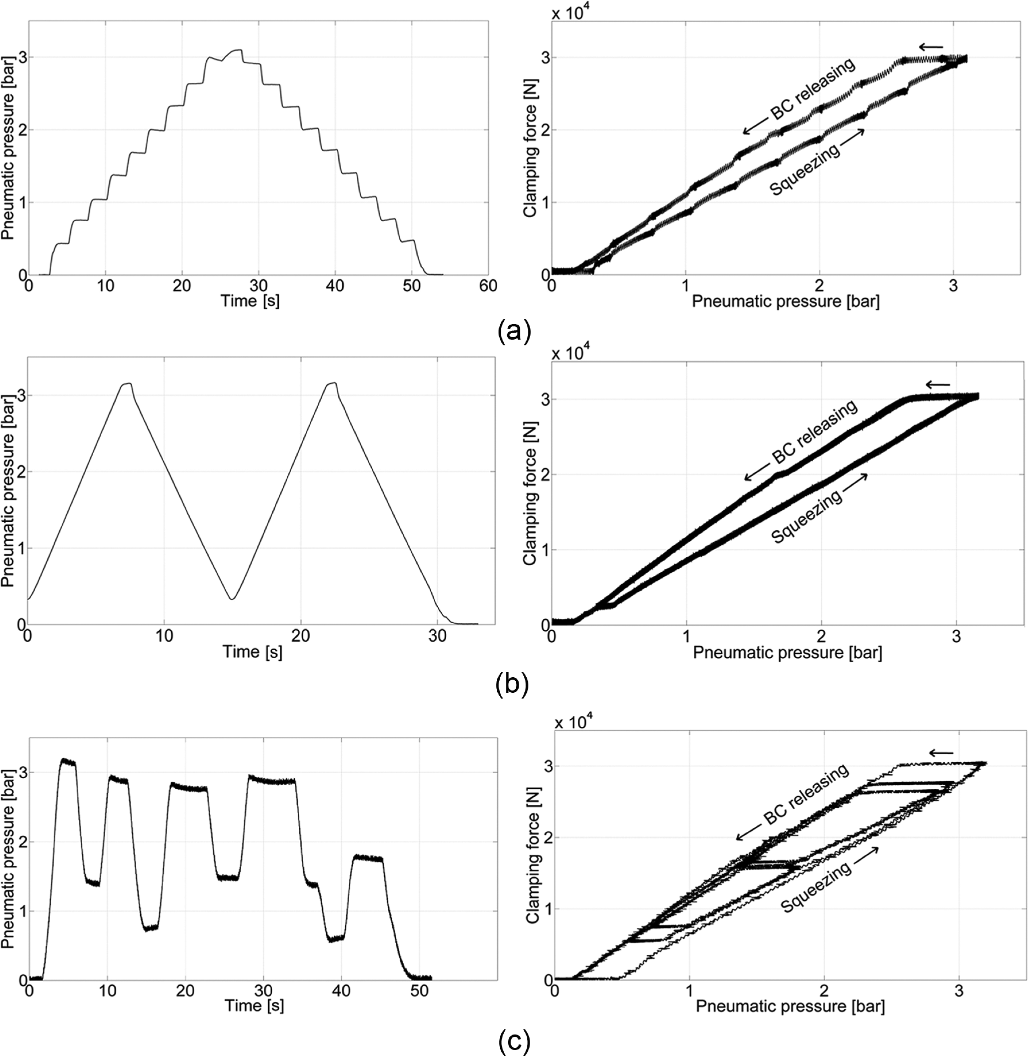
Three types of pneumatic pressure at the inlet of the brake cylinder (left) and the three measured clamping forces corresponding to each input pressure (right). (a) Stepwise input pressure variation, (b) triangular input pressure variation, and (c) random variation of input pressure.
Hysteresis measurement of a brake caliper
In the brake HILS system, a measured clamping force of the brake caliper and three computed clamping forces were obtained. They were subsequently sent to a dSPACE device as simulation inputs of the vehicle dynamics and contact model. The measured clamping force was obtained from three loadcells placed between the train wheel and the brake pad.
In this section, the clamping forces of the brake caliper were obtained in the cases where WSP valves were bypassed, and vehicle dynamics were not accounted for, and in the cases where WSP valves were operated with on–off actions, and where vehicle dynamics were considered.
For the experiments in which WSP valves were not operated and car dynamics were not accounted for, three types of pneumatic pressure variations of the BC were considered as inputs: (a) stepwise variation, (b) triangular variation, and (c) random variation. Measured clamping forces were plotted for all three types of input pressure variations in Figure 7(a)–(c), respectively. In Figure 7, the rising parts of the pneumatic pressure in the subplots on the left correspond to the squeezing phase of the clamping force diagrams in the subplots on the right, while the falling parts of the pneumatic pressure correspond to the releasing phases of the clamping force plots. Regardless of the types of the input pressure, the measured clamping forces show the same pattern. That is, they show that the brake caliper exhibits a highly nonlinear hysteresis in view of its input pressure versus the output clamping force.
Hysteresis was mainly caused by a precompressed spring inside the cylinder, the automatic clearance adjuster, lever flexibility, and the frictional forces in the cylinder and lever system that varied as a function of pressure. The BC in our HILS system had approximately a 6-in piston diameter, and the measured hysteresis at the high clamping force was approximately 0.5 bar, including the leverage system hysteresis, as shown in Figure 7.
In the latter cases that accounted for vehicle dynamics and WSP valve operations, the pneumatic pressure of the BC changed rapidly. For the experiments in which the car dynamics and wheel–rail contact model were included, we first fixed the friction coefficient to a set value for wet conditions and applied brake commands at 80%, 90%, and 100% of the full-brake command. The resulting clamping force and pneumatic pressure are plotted in Figure 8(a). We then fixed the full-brake command setting and changed the initial friction coefficient to take the values of 0.09, 0.10, 0.11, and 0.12. The resulting clamping force and pneumatic pressure are plotted in Figure 8(b). The initial friction coefficient,


where

In the equations listed above,

Experimental clamping force versus the pneumatic pressure curves when brake commands were applied at (a) 80%, 90%, and 100% of the full-brake command at a wet-rail condition and (b) initial friction coefficient
In Figure 8(a) and (b), several wheel slides and re-adhesions occur. Consequently, several loops occur along the squeezing phases and the WSP releasing phases in the clamping force versus the pneumatic pressure curves, as the vehicle speed decreases from 30 to 5 km/h. Eventually, the vehicle stops, the clamping force increases to its maximum value and then decreases to zero along the BC releasing phase. The WSP releasing phase is the phase at which the WSP valves were operating due to the wheel slides. In contrast, the BC releasing phase is the phase at which the WSP valves are not operated but bypassed, and the brake releasing occurred due to the decrease in the BC pressure. It is shown that the clamping force of the WSP releasing phase is larger than that developed at the BC releasing phase, but the magnitude of the brake command does not affect the slopes of the clamping force versus the pneumatic pressure curves.
As the initial friction coefficient
Hysteresis modeling
The measured clamping forces of the brake caliper for the BC releasing phase with the bypassed WSP valve were larger in value than the ones developed during the WSP releasing phases, but the patterns of these clamping forces are the same, as shown in Figure 7. As illustrated in Figure 7, the hysteresis curves can be approximately modeled by linear equations with different slopes and y intercepts. The clamping force developed during the squeezing phase,
For a BC squeezing phase

For a BC releasing phase

For a WSP squeezing phase

For a WSP releasing phase

where
For the brake HILS system of a Korean intercity railway vehicle at a maximum commercial speed of 180 km/h, the parameter values obtained for the hysteresis model in relation to equations (4), (5), (6), and (7) are given in Table 1.
Parameter values of the hysteresis model for the brake HILS system.
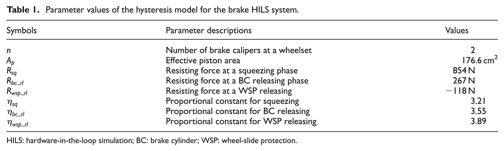
HILS: hardware-in-the-loop simulation; BC: brake cylinder; WSP: wheel-slide protection.
Identification of pneumatic cylinder dynamics
Figure 9(a) shows the difference between the measured pressures of cylinder 1 (air tank 1) and air tank 2 during the braking period with wheel sliding. Air tank 1 is connected to BC 1, while air tanks 2, 3, and 4 have fixed volumes. Thus, a dynamic difference exists between air tank 1 and air tanks 2, 3, and 4, as shown in Figure 9(a). The dynamics between air tanks 1 and 2 can be identified using the MATLAB Identification Toolbox command “ident.” In order to save computational time for calculations on dynamics, we used a discrete, third-order model in which the sampling time was set to 0.5 ms that is equal to the basic sampling time of the simulation model of our brake HILS system. The identified transfer function is as follows


(a) Pressures measured from cylinder 1 (air tank 1) and air tank 2 and (b) measured pressures from cylinder 1 and compensated cylinder 2 from air tank 2.
Figure 9(b) shows the pressure variations for cylinder 1 (air tank) and the compensated cylinder 2 with the dynamics accounted for during the braking period, in accordance with equation (8). As shown in Figure 9(b), the pressure of the compensated air tank 2 can be considered as the pressure of cylinder 2 that can be used for computing the clamping force of cylinder 2.
The maximum error of 7% elicited between the measured pressures of cylinder 1 and air tank 2 in Figure 9(a) is minimized to less than 2% by considering the BC dynamics, as shown in Figure 9(b). Even if there is a short flexible hose between the air tank 1 and the BC 1, the pressures of the air tank 1 and the BC 1 are measured to be almost the same. Thus, in this article, we neglected the flexible hose dynamics and considered that the two pressures of the air tank 1 and cylinder 1 were the same.
The clamping force of caliper 1 for wheelset 1 was measured using loadcells, but the clamping forces for wheelsets 2, 3, and 4 were computed using equations (4)–(7) from measured air tank pressures. One measured clamping force and the three computed clamping forces were fed back to the vehicle dynamics module in order to stop the train.
Figure 10 shows three sets of clamping forces versus pneumatic pressure plots. The straight line is the computed clamping force from the pressure of air tank 1 without consideration of hysteresis and BC dynamics, which is much different from the actual clamping force. The second curve in black color is the measured clamping force for wheelset 1 with the brake caliper, in which vehicle dynamics were accounted for HILS. The third curve marked in red is a computed clamping force for wheelset 1 from the measured pneumatic pressure of air tank 1. As you can see, the trend of the measured force (plotted in black) and the computed force (plotted in red) are the same with a maximum ±8% error in magnitude. This observation indicates that the presently used models for hysteresis and BC dynamics are acceptable.
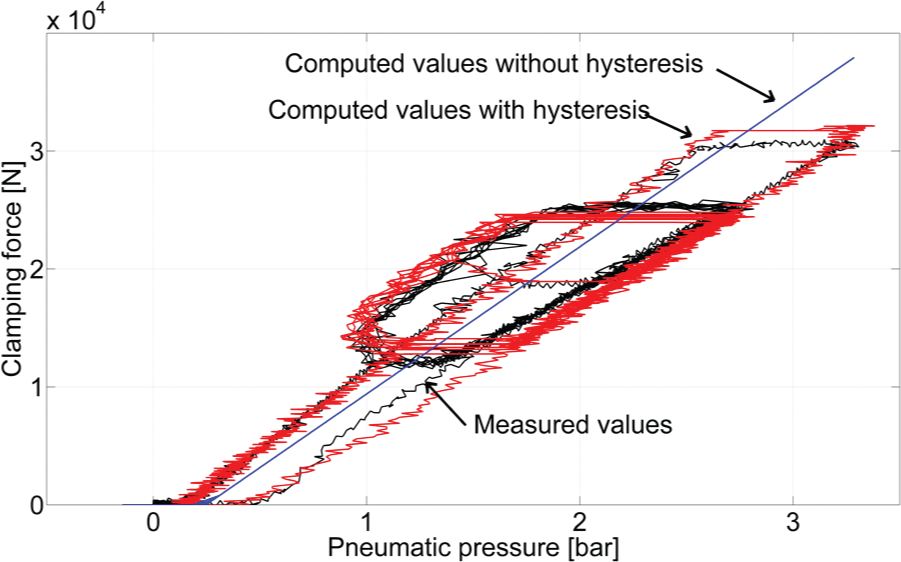
Measured clamping force at wheelset 1 with a brake caliper and computed clamping force based on the pneumatic pressure measurement of air tank 1 for wheelset 1.
HILS for WSP
In order to demonstrate the validity of the modeling for hysteresis and BC dynamics, we applied the models to WSP of wheelsets 2, 3, and 4. Before conducting HILS for WSP, we carried out slip-brake tests to ascertain whether the developed brake HILS system satisfies the test evaluation criteria of the UIC Code 541-05 (Appendix B) for a brake HILS system. This code specifies that the initial adhesion should be less than 0.08 g deceleration in the first phase of the braking, the minimum slide for an initial speed of 120 km/h should be greater than 35% for at least a half of the wheelsets of the vehicle, and the braking distance should be 440–490 m for an initial speed of 120 km/h and a brake position R. The evaluation results from the tests are shown in Figure 11, and they are summarized in Table 2, showing that all the criteria in the UIC Code 541-05 (Appendix B) are satisfied.

Experimental results for the test evaluation criteria in UIC Code 541-05 (Appendix B) on (a) initial adhesion and (b) minimum slide.
Summary of the experimental results for the test evaluation criteria in UIC 541-05 (Appendix B).

GM: Glissement minimum.
Figure 12(a) shows slide test results on commercial rails in Korea using an actual intercity train with an initial speed of 80 km/h according to the UIC Code 541-05, in which the braking time was 17.6 s, the braking distance was 197 m, and the deceleration changed from 0.98 to 1.52 m/s2. Figure 12(b) shows the HILS results using the developed brake HILS system, in which the initial speed was set to 80 km/h, and all the parameter values and WSP logic were set to be the same as the ones used for the intercity train in Figure 12(a), except for the adhesion coefficient between the wheels and rails. We tried to ensure that the adhesion coefficient of the HILS system was the same as that of the actual train, but we could not emulate exactly the same conditions that affect the adhesion coefficient as those encountered in reality. Figure 12(a) and (b) shows the same patterns of skid and re-adhesion, but they have a different braking time and distance. The difference in the braking time of Figure 12(a) and (b) is mainly due to the discrepancy of the adhesion coefficients. In Figure 12(b), the four different wheelset speeds elicit similar patterns, in which wheelset 1 has a brake caliper and an actual BC, but wheelsets 2, 3, and 4 only have air tanks corresponding to the BC volume, hysteresis logic, and BC dynamics. This demonstrates the validity of the proposed HILS system construction with the modes on hysteresis and BC dynamics.

Results of slide tests with an initial speed of 80 km/h, using (a) an actual intercity passenger train at a commercial speed of 180 km/h and (b) the developed brake HILS system with hysteresis and brake cylinder dynamics.
Figure 13 shows the clamping forces of the brake caliper for wheelsets 1 and 2 during a braking period. The curve in Figure 13(a) is the clamping force measured as the sum of the three loadcells at wheelset 1, and the two curves in Figure 13(b) are the clamping forces computed from the measured air tank pressure at wheelset 2. One of these forces in Figure 13(b) accounts for hysteresis and BC dynamics models, and the other does not. The computed clamping force that accounted for hysteresis and BC dynamics at the wheelset 2 is much similar to the measured clamping force at wheelset 1 in both magnitude and frequency. The number of WSP valve actuations (opening and closing) for wheelset 1 with an actual caliper was 11, as shown in Figure 13(a). The number of WSP valve actuations for wheelset 2 without a caliper was equal to 21 for the case where hysteresis and BC dynamics were not accounted for, and equal to 11 for the case where hysteresis and BC dynamics were accounted for. Moreover, it is the same as that for wheelset 1. This is another demonstration of the validity on the inclusion of hysteresis and BC models in the brake HILS system. More frequent WSP valve actuation means more air consumption, which implies the need for a bigger air compressor and reservoirs.

Results of slide tests using the brake HILS system. (a) Measured clamping force from loadcells for wheelset 1, (b) computed clamping force from measured pneumatic pressure of the air tank for wheelset 2, with and without consideration for hysteresis and brake cylinder dynamics.
Conclusion
In this article, we implemented a brake HILS system with only one brake caliper and three air tanks, accounting for hysteresis and BC models, which resulted in saving installation space and reducing costs for constructing a brake HILS system of a railway vehicle, compared to the four-brake caliper systems. Since the brake caliper exhibited a major hysteresis nonlinearity and non-negligible BC dynamics, we incorporated mathematical models to account for hysteresis and BC dynamics in the air tank modules. The hysteresis of the brake caliper was modeled by measuring the clamping force of the caliper using loadcells, and the BC dynamics were modeled in discrete time, with a 0.5-ms sampling time using the identification toolbox of MATLAB.
In the developed HILS system, one of the clamping forces was measured using loadcells, and the other three were computed clamping forces from measured pneumatic pressures. These force values were subsequently supplied to the input of the vehicle dynamics module using a dSPACE device. The BOU generated four clamping forces through the use of one caliper and three air tanks, using the real-time simulation results on vehicle and wheelset speeds.
The proposed method that was constructed with a brake HILS system using one caliper and three air tanks, with consideration of hysteresis and BC dynamics models, was demonstrated through its application to WSP tests of an intercity train. Computed clamping forces with hysteresis and BC dynamics at wheelset 2 was similar to the measured clamping force at wheelset 1 in both magnitude and frequency, compared to the computed clamping force without consideration of hysteresis and BC dynamics at wheelset 2.
Footnotes
Academic Editor: Crinela Pislaru
Declaration of conflicting interests
The author(s) declared no potential conflicts of interest with respect to the research, authorship, and/or publication of this article.
Funding
The author(s) disclosed receipt of the following financial support for the research, authorship, and/or publication of this article: This research was supported by Basic Science Research Program through the National Research Foundation of Korea (NRF) funded by the Ministry of Education (grant number 2013R1A1A2062374).