
Abstract
Frequency-shift keying audio jointless track circuit is used in high-speed railway in China. However, within the station, track circuit with mechanical insulation is applied. In complex circuit network of electrified railway station, impedance match bond is designed to ensure the normal operation of the track circuit and the protection of strong traction current interference. As a combination of strong and weak electricity components of track circuit, impedance match bond is both the part of the loop of the traction current and the part of the transmission line of track circuit, playing a very critical role in the electrified railway. The structure of impedance match bond is more complex than traditional impedance transformer, including the transformer with larger air-gap, LC resonance circuit for power frequency filtering, and components to enhance the signal frequency. Modeling on impedance match bond and study about the four-terminal network parameters of impedance match bond are in favor of the following two aspects: modeling of the overall traction current and calculation of track circuit working condition. By applying the transformer equivalent circuit model and combination of testing and calculation, the accurate model of impedance match bond is constructed and verified. Finally, for ease of track circuit calculation, four-terminal network model of impedance match bond under different signal carrier frequencies is presented.
Research background
Signal equipment plays the key role in Chinese Train Control System (CTCS) to ensure the safety of high-speed railway operation and improve the efficiency of railway transportation. CTCS-3 features Global System for Mobile Communications-Railway (GSM-R), balise, and traditional track circuit; 1 the characteristics of the standard about this system are also illustrated. As one of the main signal equipment, 2 the ZPW-2000 series jointless track circuit is used widely in high-speed railway in China. The modulation of such track circuit is narrowband frequency-shift keying (FSK), and the carrier frequencies are, respectively, 1700, 2000, 2300, and 2600 Hz. However, insulated track circuit is needed in the station, of which the insulation section is a mechanical one. To enable the application of the insulated track circuit at the station, the previous impedance transformer was adopted.
However, the traditional impedance transformer has relatively poor performance in anti-unbalanced traction current. In addition, it presents low impedance at the carrier frequency of the signal. Thus, impedance match bond (IMB) has been designed and developed by us. In contrast to the traditional impedance transformer, the characteristics of the IMB are as follows: (1) to meet both the requirement of the immunity against traction current and the impedance requirement at the carrier frequency of the signal, the secondary side of the transformer is connected to an adapter in parallel. By reasonable design, the IMB may present low impedance to the power current, but reach parallel resonance at the carrier frequency and thus present high impedance to the signal. (2) To prevent the transformer saturation caused by the large unbalanced traction current, an air-gap is opened on the iron core of primary side of the IMB.
The diagram of the insulated track circuit and the IMB at the station is shown in Figure 1. IMB can be seen as a whole part paralleled with the sending and receiving ends of the ZPW-2000 track circuit. It is necessary to model and analyze the IMB. The first reason is, as a part of the traction power supply system, impedance characteristics of the device will influence the distribution of traction current. The second reason is that to evaluate the transmission characteristics of track circuit, track circuit system modeling and computing are required.
Track circuit at station.
An IMB with capacity of 1000 A is discussed as an example in this article, of which the index of anti-unbalanced traction current is above 15%. The IMB consists of two parts, the transformer T and the adapter. The circuit structure of IMB is shown in Figure 2. Due to the low impedance characteristics for power frequency, the adapter is used to reduce the interference of the unbalanced power traction current. In order to prevent the surge current, there is a relatively large air-gap in the iron core of the transformer, which may reduce the impedance within the signal frequency band, and thus affect the useful signal energy at the receiving end. 3 Therefore, a parallel resonant capacitance is applied in secondary of the IMB, to reduce the interference of power frequency current and shall not affect the frequency shift impedance. The railway standard of China 4 specifies that such impedance should not be less than 17 Ω. To calculate the transmission characteristics of track circuit, equipment is usually equivalent to four-terminal network, represented by the admittance parameter matrix N. In this context, the modeling of the IMB and the configuration of the four-terminal network are necessary for the calculation of the track circuit.
Circuit diagram of the IMB.
Some researches on the modeling of the traditional impedance transformer have been done. An equivalent circuit of the impedance transformer was proposed, consisting of three parts: an ideal autotransformer, an equivalent circuit of T-shape, and an ideal transformer with the corresponding transformation ratio 5 ; magnetic circuit model of the impedance transformer was built based on the mathematical model and the simulation results. 6 Researches on the magnetic saturation problem of impedance transformer and the prevention method have also been done. For example, to avoid magnetic saturation resulting from large unbalanced traction current, measures of an enlarged air-gap in the iron core and an added adapter in the transformer were adopted. 7 Magnetic storm may result in approximate direct current in rails. The unbalanced part of the direct current (DC) may interfere with the impedance transformer and cause magnetic saturation. 8 However, these researches are all based on the impedance transformers for 25-Hz phase-sensitive 9 or Chinese frequency shift track circuit (its carrier frequency range is from 550 to 850 Hz). Researches on the IMB, especially for the ZPW-2000 track circuit, have not been seen in the published literature.
The equivalent circuit model of IMB is first proposed and then its validity is verified through simulation and test in this article. To facilitate the calculation of transmission characteristics of track circuit system containing IMB, the four-terminal network coefficient matrix of IMB is established based on IMB equivalent circuit model. And the coefficient matrixes of the IMB at four carrier frequencies have been calculated.
Model of the IMB and the key parameters
There are three typical equivalent models for transformer: circuit model, mutual inductance model, and magnetic circuit model. The impedance model of the IMB is mainly concerned in this article. At carrier frequencies, the impedance of the secondary is large, and the current in the iron core cannot be ignored. Both the core loss and the nonlinearity of the exciting current should be considered. In the mutual inductance model, both the loss and the nonlinearity are ignored, and so the characteristics of the IMB cannot be accurately represented. Magnetic circuit model is also based on the principle of mutual inductance and has the similar defects. In contrast, these defects may be avoided in the equivalent circuit model, which is chosen for the IMB in this article.
In the equivalent circuit model of the IMB, parallel equivalent circuit model was applied in the equivalent model of transformer T.8,9 The exciting current then can be divided into active component and reactive component. That is, the exciting current consists of the pure magnetizing current which results in the main flux linkage and the active current which results in the iron loss. Equivalent secondary side leakage impedance to the primary side, T model can be simplified as shown in Figure 3, R1 for coil winding resistance, ZL for leakage impedance, Lm for excitation inductance, and Rm for the iron loss equivalent resistance. Due to the large air-gap in the iron core, the impedance transformer cannot reach saturation state, and thus, the model works in linear zone, that is, to take Lm and Rm as constant. I1 is the primary current, IΦ is the excitation current, I2 is the current in the primary converted from the secondary current, Ic is the loss current, and Im is the magnetizing current, 10 complying with equations (1) and (2)


T-shape equivalent circuit of the transformer.
To get the accurate model, model parameters should be as accurate as possible. As shown in Figure 3, the following parameters should be first obtained: the resistance of coil winding R1, leakage impedance ZL, excitation inductance Lm, and the iron loss equivalent resistance Rm.
Leakage impedance and DC resistance test
Coil winding resistance r and leakage inductance ZL can be obtained through the short-circuit experiment. 11 There are four carrier frequencies in ZPW-2000 track circuit, that is, 1700, 2000, 2300 and 2600 Hz. Without loss of generality, the carrier frequency of 2300 Hz is applied. The equivalent leakage impedance of the primary side is obtained when the secondary side is short-circuited. The test results of IMB equivalent leakage impedance at 2300 Hz are shown in Figure 4. According to the results, the average value is close to 0.2 Ω.

IMB equivalent leakage impedance at 2300 Hz.
Under the condition of disconnecting the adapter, the DC resistance of the traction coil has been measured. The test results are shown in Figure 5. The DC resistance of the traction coil can be 0.025 Ω.

DC resistance of traction coil.
Due to the skin effect and proximity effect, winding resistance varies with frequency. But within a certain frequency range, the resistance can be considered as essentially constant. Based on the above test results, the leakage impedance ZL generated by carrier frequency is very small; thus it can be ignored in the complete model.
Transformer excitation inductance Lm and iron loss equivalent resistance Rm
Lm and Rm of impedance transformer are the key parameters in the equivalent circuit. Lm is determined by primary and secondary inductance and mutual inductance. In order to improve the capability of anti-interference of unbalanced traction current in the track circuit, an air-gap is opened up in the impedance transformer to prevent saturation problem caused by large power frequency current. Since the saturation point of the transformer has shifted backward after opening up the air-gap, the linearity of excitation inductance has been improved. Under the condition of the opened air-gap in iron core, if the air-gap length g is small enough, the structure can be analyzed by a magnetic circuit consisting of two parts in series, assuming that magnetic flux density of the core is uniform. Because the magnetic resistance of the iron core Rc is far less than the magnetic resistance of the air-gap Rg, it is a reasonable approximation that the inductance can be determined by the air-gap magnetic resistance. 11
Equation (3) represents the equivalent inductance when the air-gap is open

where µg is the magnetic permeability of the air-gap, Ag is the cross-sectional area of the air-gap, and g is the length of the air-gap. According to the circuit design parameters, it can be known that Lm = 2.57 mH. After obtaining the value of Lm, it can be calculated that Z is 5.87 Ω through the experiment. Then, Rm is deducted by the relation between Z and Lm

It can be calculated that Rm = 51.94 Ω.
Determination of key parameters for the adapter
In addition to presenting low impedance to the frequency of 50 Hz, another function of adapter is to enhance the signal impedance by reaching the parallel resonance of both the capacitance and the secondary side excitation inductance under the condition of carrier frequency. 12 But in the above-mentioned impedance transformer model, secondary side excitation impedance is not reflected. To obtain a complete model, the primary side should be connected to the adapter and the excitation inductance L3 of the secondary side coil by an ideal transformer. After working out the impedance of the secondary side, the impedance is then converted to primary side through the ideal transformer.
To obtain a complete model, it is also needed to determine the transformer ratio N. The adapter at 50 Hz should be connected in series with the capacitance Ca1, inductance La, and its equivalent resistance r (or quality factor of the circuit) in the resonant circuit and connected in parallel with the resonant capacitance Ca2. Since Ca1, Ca2, La, and transformer ratio N are known, it is only needed to determine the excitation inductance of secondary side coil L3 and the equivalent resistance of iron core inductor r, assuming that Rm and Lm are fixed. According to the circuit of Figure 6, equations (5) and (6) may be obtained


Simplified equivalent circuit model.
According to practical design and test data, 13 the values are determined as follows: the iron loss equivalent resistance Rm = 51.94 Ω; excitation inductance Lm = 2.57 mH; the ideal transformer ratio of T2 is n = N2:N1 = 30; and adapter parameters Ca2 = 30 µF, La2 = 0.3377 H, L3 = 2.313 H, and Q = 25. It should be noted that the value of Ca1 varies with different carrier frequencies.
With Lm = 2.57 mH, it can be calculated that L3 = 2.313 H.
With La2 = 0.3377 H and Q = 25, it can be calculated that r = 4.24 Ω.
Equivalent circuit model simulation and test verification
Impedance characteristics at different frequencies
According to the circuit diagram and parameters shown in Figure 6, MATLAB is adopted for programming and calculation. The frequency–impedance responses in scenarios of IMB and IMB without adapter are obtained, as shown in Figure 7.
Frequency–impedance responses in scenarios of IMB and IMB without adapter.
It can be seen from Figure 7 that the impedance of the IMB without adapter is directly proportional to the frequency due to the nature of inductance and the impedance value is around 30 Ω. By adding an adapter, impedance of the IMB reaches the peak value of about 45 Ω at 2300 Hz because the parallel resonance happens in the circuit at this frequency point. The resonant frequency of 2300 Hz is designed intentionally to obtain the larger impedance which may improve the transmission of the signal of 2300 Hz.
Test and model verification within the working voltage range
Within the range of working voltage from 0.5 to 8 V, the impedance of the IMB and impedance of the IMB without the adapter have been tested at the frequency of 2300 Hz. The results are shown in Figure 8. At 2300 Hz, the average impedance of the IMB is about 43 Ω and the average impedance of the IMB without adapter is about 30 Ω. In the working voltage range, the measured results shown in Figure 8 are in line with the simulation results at 2300 Hz as shown in Figure 7.

IMB impedance responses at 2300 Hz.
Generally, in the comprehensive analysis of four-terminal network of track circuit and traction power supply system, traction current and signal current are added on the impedance transformer simultaneously. The above-mentioned model can be applied to the analysis under the condition of traction current and signal current.
Four-terminal model parameters of IMB
In the calculation of the transmission of tract circuit, the commonly used method is to make each device equivalent to four-terminal network, as shown in Figure 9; then each four-terminal network can be connected in series to construct a complicated system model.
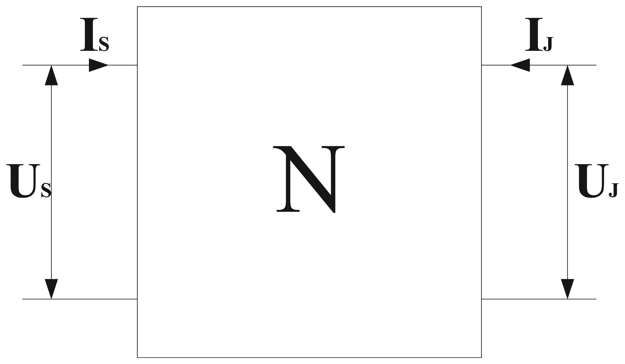
Four-terminal network.
The corresponding transmission equation for N can be applied in
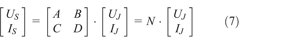
Four-terminal network coefficient matrix is expressed as follows

In general, each four-terminal network probably comprises three basic circuits as shown in Figure 10.
The matrix elements of Figure 10(a)–(c) are, respectively 14


Circuits of basic units: (a) series impedance, (b) parallel impedance, and (c) transformer.
In the comprehensive analysis of four-terminal network of track circuit and traction power supply system, traction current and signal current are added on the impedance transformer simultaneously. Thus, parameter variation with frequency should be taken into consideration. Based on the above analysis, IMB model consists of four parts, including an autotransformer, an equivalent circuit of excitation impedance, an ideal transformer, and an equivalent circuit of the secondary side. Then NZPW of the IMB model shown in Figure 6 can be deducted as follows

The calculation results of NZPW can be referred to Table 1.
Calculated NZPW of IMB in track circuit (transformation ratio is 1:30).

Conclusion
This article constructs a model of IMB used in Chinese high-speed railway through testing and theoretical calculation. After parameter optimization, the simulated results fit very well with the test data. In addition, a four-terminal network model has been proposed. The equivalent four-terminal network parameters under different conditions have been calculated, providing the necessary foundation for complete modeling and calculation for track circuit system.
In the article, first innovation lies in the modeling of IMB and derivation of equivalent circuit equation, which could manifest the effect of air-gap. The second innovation is to measure the adapter’s impact on the primary impedance of IMB, and the result can be applied in railway engineering. The modeling method proposed in this article is helpful for analyzing complicated impedance transformer, by which the complete calculation of the transmission characteristics of track circuit can be more feasible.
The model and the parameters given above have been used in the working condition calculation of track circuit in many high railway stations. And it has been proved that the calculation results agree very well with real conditions.
It should be noted that at different carrier frequencies (1700/2000/2600 Hz) other than the frequency of 2300 Hz, the model maintains the same but parameters may change. Due to the nonlinear characteristics of Rm and Lm, the model should be further modified and optimized for various frequencies.
Footnotes
Academic Editor: Fakher Chaari
Declaration of Conflicting Interests
The author(s) declared no potential conflicts of interest with respect to the research, authorship, and/or publication of this article.
Funding
The author(s) disclosed receipt of the following financial support for the research, authorship, and/or publication of this article: this work was supported by the Science and Technology Development Program of China Railway Corporation in 2014 (2014X008-I) and the National Science Foundation of China (NSFC, grant no. 61227002).