
Abstract
The full potential of plastic gear usage is limited by not only poor mechanical properties but also equally poor temperature limits and poor heat conduction properties. Cooling holes were developed to decrease the amount of thermal damage on the contact surface. These cooling holes promote increased stress and tooth deflection, thus exerting a negative effect. This article compares various cooling holes for plastic gear configurations and proposes novel cooling holes. Thermal and mechanical simulations that consider specific aspects of plastic gear meshing were performed. The main objective of this article was to verify the best methods for reducing thermal damage through cooling holes. The results indicate the best compromise between the temperature reduction and the mechanical properties of the new tooth geometry. The results also indicate that the simple variations in the cooling holes proposed can improve tooth performance.
Introduction
Metal gears have been replaced by plastic gears in recent years due to their economic advantages. 1 The industry appreciates the economic and technical advantages of polymer gears (e.g. ability to operate without grease or oil lubrication, low cost of production, low density, high resilience, and internal damping capacity), and thus, the use of plastic gears is steadily increasing. 2 Some examples of the field applications of plastic gears include the automotive industry, office machines and household utensils, and food and textile machinery.2,3
In the specific case of gears, the major differences between metallic gear behavior and plastic gear behavior can be attributed to the elastic moduli of plastics, which is approximately 100 times less than the elastic moduli of the majority of steels and 30 times less than the elastic moduli of aluminum. Plastic gear meshing involves an extension of the contact between the teeth outside the line of action, before the beginning and after the end of the theoretical engagement. 4 The large deformation of a tooth during meshing tends to relieve each pair of teeth in contact. In the case of gears, the low moduli of polymers were historically considered to be desirable because the transmitted load is better distributed and both noise and contact forces are reduced during motion. 5
The temperature is often described as the main cause of failure in plastic gears due to their low melting point and low conductive properties. 6 The heat that is locally generated remains concentrated and does not dissipate. This phenomenon is the cause of thermal degradation, which is exclusive to plastic gears.7,8
The heat produced during meshing causes a temperature distribution with significant localized instantaneous elevations in specific regions for points in the meshing due to the Hertzian contact and the low thermal conductivity of plastics.
Gears are known key parts of many power transmission systems; their eventual failure can ultimately cause the catastrophic failure of many modern machines because they are widespread mechanical elements.
The full potential of plastic gears should be considered when addressing its temperature limitation. Several approaches were employed to decrease the temperature of the plastic tooth. In a study by İmrek, 9 the values of load-transmitted force by tooth width (F/b), in single- and double-tooth meshing zones, were leveled by widening the single-tooth area width, and the performance of both modified and unmodified gears was experimentally assessed using three different loadings. Modified Nylon 6 gears exhibit lower tooth temperatures with better results in terms of wear and gear performance.
In a similar study, Düzcükoğlu 10 observed the delay of the formation of thermal damage in the region of single-tooth meshing by decreasing the Hertzian surface pressure and increasing the tooth width. The F/b tooth load was decreased in the single-tooth-pair contact region. The experiments showed that the appearance of thermal damage is delayed for the width-modified gear teeth compared with unmodified gear teeth.
Düzcükoğlu 11 also investigated the effect of cooling holes on the accumulated heat on the tooth surface and the measured wear. The drilled cooling holes on the tooth body decreased the tooth surface temperature and increased the load-carrying capacity and wear resistance. Geometrically modified gears have contributed to an improved service life and decreased surface temperature.
We propose that air-cooling holes be drilled on the plastic gear tooth in different locations to reduce the tooth temperature by transferring the heat from the tooth through these holes via convection. 12 These holes decrease not only the temperature but also the tooth mechanical performance. Instead of an experimental study, this study comprises a numerical study that considers the particulates of the plastic gear simulation. Plastic gear meshing presents some particularities that differ from metallic meshing. These particularities must be added to a model for an accurate simulation. This article compares various cooling holes for plastic gear configurations and proposes novel cooling holes.
This article is organized as follows. First, the pertinent theory of plastic spur gear simulations is reviewed in three parts: the particularities of plastic gear meshing, the distribution of the transmitted normal load, and the sliding speed characteristics. The heat mechanism is then studied. It is important to note that the generation of heat in plastic gears is very dependent on the meshing characteristics of the gears, which are reviewed in the first section. The third section presents the cases that will be studied, and the fourth section presents the validation and thermal simulation results. The mechanical simulations are presented in the fifth section. The implications of the thermal and mechanical results are studied using a combinational trade-off analysis in the sixth section, and finally, the conclusions are then presented.
Plastic gear particularities
Particularities of plastic gear meshing
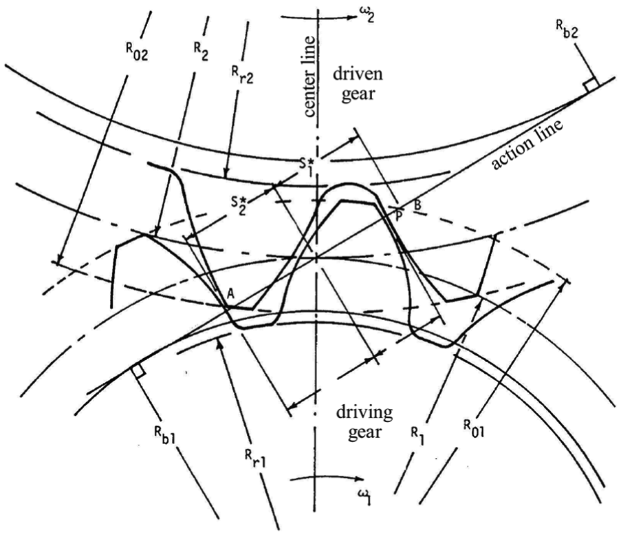
In this section, we discuss aspects of plastic gear meshing that must be considered when a model is implemented. When the gears are composed of thermoplastic, the contact ceases to be exclusively located on the line of action (Figure 1); several authors have demonstrated this characteristic behavior.8,13,14

Real and theoretical paths of contact. 14
When the gears are considered to be rigid, the pair of teeth is in contact at the start point of contact A, where the theoretical tip circle of the driven tooth (wheel) intersects the line of action; contact ceases at end point B, where the theoretical contact tip circle of the drive teeth (pinion) cuts the line of action (Figure 2).
Theoretical spur gear load transfer points.
For these gears, the normalized position of the theoretical contact start point following the line of action with respect to the pitch point (gear 2 as a reference) is expressed as

The expression for the normalized position of the theoretical contact end is obtained from equation (1), in which subscript 2 is replaced by subscript 1. By convention, when the driven gear is used as a reference, S/pn has a negative value during the approach phase. When the contact point is below the pitch circle of the tooth of pinion 1, S/pn has a positive value during the withdrawal phase, and the point of contact during this phase is above the pitch circle of the sprocket tooth.
The deformation outside the line of contact was demonstrated by Gauvin et al. 15 using high-speed photography (Figure 3). The dynamic loads for plastic gears are damped by the viscoelastic nature of the material. 7 The experimental measurements13,16 and theoretical studies have supported the existence of this particular engagement. 15 Koffi 7 established a simplified method to calculate the normalized position of the contact start point by evaluating the difference along the line of action between the theoretical contact and actual contact

Increase in the contact ratio due to tooth deformation under loading. Three points of contact occur simultaneously, but only the central point is on the line of action.
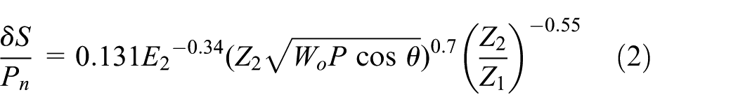
Equation (2) establishes a power law between the normalized deviation δS/pn and W0 P cos θ. Any increase in P at a constant diameter increases the number of teeth Z, which causes a reduction in the normal load Wn by the load distribution factor Wi/W; the value of Wi/W at the pitch point Wi/W|0 decreases according to a power law with an increase in the diametral pitch P. 7
The normalized increase in


This notion will be important when determining the sliding speed and, consequently, the heat generation.
Distribution of the transmitted normal load
The normal load transmitted to a pair of teeth Wn continuously varies along the contact path. The actual contact length A′–C′, which corresponds to the actual contact ratio, differs from the theoretical contact length A–C. This discrepancy causes an increase in the real contact ratio (RCR) and reduces the maximum load that can be applied to a pair of teeth.
Yelle 17 calculated the factors from an exact analytical study using a study based on geometry and static balance. For practical modeling purposes, the simplified model is employed; this model calculates the load distribution factor at any position during the engagement from the value of Wi/W to the original point or Wi/W|0 for a plastic–plastic engagement, given by the following expression 18

The value of S2/pn is obtained from equation (3).
Wi/W|0 is a function of the load and the material and geometry of the gear; its expression is as follows

Sliding speed
In addition to the relative rolling movement of gear teeth, the movement of a pair of contacting gear teeth comprises a sliding of one of the teeth relative to the remaining teeth. This phenomenon creates a frictional force at the contact point; the displacement of the frictional force with the point of contact causes friction losses and tooth heating.
The instantaneous slip velocity is defined as the difference between the instantaneous speed on the side of the driving and driven teeth at which the point of contact moves. 19 Inside the line of action, the sliding speed is 17

V is the linear speed at the pitch circle. For contact outside the line of action (in the approach phase), the equation becomes 17

with


Figure 4 shows the important angles for the calculation outside the line of action. During the withdrawal phase, the expression of the speed (equation (8)) does not change for a contact that occurs along the line of action. For a contact that occurs outside the line of action, the sliding speed is obtained by interchanging indices 1 and 2 in equations (9)–(12).

Important angles for the calculation of the sliding speed outside the line of action.
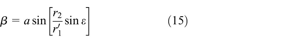
To calculate the sliding speed outside the line of action, the specific angles (

It can be shown that

For the cosine law

Once
Similarly, during the recess phase, the corner of tooth c1 makes contact with the flank of tooth c2, where
The absolute value of the sliding speed continuously increases when the contact point moves outside of the theoretical bounds S2/pn (approach) and Sl/pn (retreat). The first point and last point of contact—
Heat production mechanism
With the specificities of the plastic gear meshing discussed, it is possible to calculate the heat generated during this process at each point. The displacement of the frictional force creates work, which manifests as heating of the surface of the tooth and, in the long term, the entire tooth. The value of the heat of friction per unit time primarily depends on the friction force and slip speed, which vary with the mechanical or physical properties and parameters.7,17
From the beginning to the end of real contact, the amount of heat generated by sliding friction between two teeth is evaluated by integrating the product over the course of the contact

This product represents the work of the frictional force during the interval of infinitesimal time dt. From the expression of the frictional heat for an infinitesimal time interval dt (equation (16)), this heat is directly related to the expression of the frictional force Ff, which is the friction force in the expression of the frictional heat (equation (16)), which is directly dependent on the value of the distribution factor of the transmitted normal load Wi/W. This factor is multiplied by the normal load Wn to yield the actual load, as previously discussed.
The distribution of Wi/W is dependent on the degree of contact that extends from the line of action, which is a phenomenon that is dependent on the nature of the materials, the geometry, and the other parameters of operation. As previously demonstrated, the expression for the slip speed differs on the outside line. According to equation (16), the frictional heat is directly related to the magnitude of the slip speed.
For contact that occurs on the line of action, the Vs slip speed is a direct function of the normalized position of the contact point S/pn. Outside the line of action, the value of Vs changes with the normalized contact position and the angles β and ε (Figure 4). The angles β and ε are a function of not only S/pn but also the normal load Wn and the modulus of elasticity of the material.
With these considerations, the frictional heat is Egh. In a spur gear, for a displacement ΔS of the contact point, the heat generated by friction for a unit face width can be expressed 17

where
The instantaneous temperature at the contact point affects a thin layer on the contact surface; the thickness of this layer is less than the contact width 2b. 21 When the temperature at the contact point is assumed to be identical for the two teeth, the following expression of the heat distribution factor φ2 is written 23

Calculating the value of φi at each position of the contact point requires the determination of a pair (V1, V2) of local instantaneous speeds. These values must be calculated for the approach and withdrawal phases and for contact on and outside the line of action.
Heat is produced by friction from the surface of two teeth in contact. The study of the temperature increase experienced by a tooth requires quantification of the heat that affects each tooth. A factor φ is determined when the total frictional heat is Ef. The multiplying factor to yield the amount of heat recovery for one tooth is φ1 Ef


where

Gear configuration
The base configuration for this study is a gear with the same dimensions and mechanical properties as investigated by Koffi. 7 This author performed extensive research of the behavior of plastic gear by the simulation and experiments, which enabled an external confirmation of the simulation parameters of the initial configuration.
As shown in Table 1, we utilize a gear with a diametral pitch of 10 (module of 2.54 mm), a standard pressure angle of 20°, and a primitive diameter of 0.0762 m. The material is ultra-high-molecular-weight polyethylene (UHMWPE). The adopted material properties are listed in Table 1.
Gear parameters.

The basic tooth geometry, which is referred to as configuration C1, is shown in Figure 5. The following proposed configurations—C2 and C3—were inspired by a study by Düzcükoğlu et al., 12 in which cooling holes were drilled in the axial and radial directions.
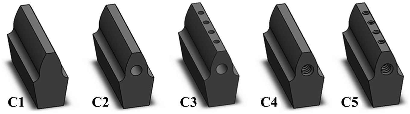
Proposed tooth configurations.
Configuration C2 contains holes in the tooth base next to the pitch radius. The radius of the drilled hole is 1.13 mm, which is the size of drill #4. The objective of this hole is to insert a dissipation area through the tooth width to dissipate the heat that is generated on the surface and cannot be evacuated.
Configuration C3 has radial holes in addition to the axial hole. These holes begin on the tooth addendum and continue until it conjuncts the axial hole. The size of these holes must be small due to the tooth involute profile; they are as large as drill #0 and four equally spaced holes are used.
The next two configurations are original propositions. Configuration C4 is similar to configuration C2. Because the objective of these cooling holes is to introduce dissipating surfaces in the tooth interior, we propose the use of a tapped hole instead of a straight hole. The hole is formed with the dimensions of the standard #4-40 tap. This configuration results in a dissipating surface that is 86% larger than configuration C2, which contains a similar amount of material removal. Similarly, configuration C5 is derived from configuration C3 but contains tapped holes. The axial thread is #4-40, and the radial threads are #0-80. The tapped hole also provides an increased dissipation of 86% with similar material removal for each hole. Details of the positions of the cooling holes are shown in Figure 6.

Details of the positions of the cooling holes: configurations C3 (left) and C5 (right). Distances in millimeters.
The dissipation holes increase the gear protection of thermal effects and decrease the mechanical strength due to material removal and stress concentrators. The same concept is valid for the proposed threaded solutions; they increase the theoretical thermal protection and introduce a stress concentrator due to their geometry.
Applied loads
Two main damage modes in plastic gears are the thermal and mechanical breakage; therefore, it is important to simulate it accurately. For this reason, the gearing process was simulated using finite element method (FEM). This method was chosen because it is a numerical procedure that can be used to obtain solutions for complicated or large-scale engineering problems involving stress analysis, heat transfer, electromagnetism, and fluid flow. 24 The tool used for this work was Dassault Systèmes SolidWorks Simulation 2014® FEM module 2014.
The performance is analyzed using thermal and mechanical simulations. The gear loads are defined by the plastic gear theoretical results using equations (5) and (6); the results are shown in Figure 7(a). The thermal loads via the gear contact face are calculated using equations (17)–(21); the results are shown in Figure 7(b). The calculation is performed using 16 equally spaced points in the contact path. The vertical red lines indicate the beginning and end of contact for a similar metal gear.

(a) Theoretical transmitted load and (b) gear face heat generation considering a path that is discretized into 16 equal segments.
The contact face in the three-dimensional (3D) model is also discretized into 16 equal regions (Figure 8(a)), and the corresponding heat is applied. Commonly, the gear is considered as a rotating disk for the determination of the heat transfer coefficient.25–27 These methods lead to two distinct heat transfer coefficients: one for the sides of the gear and other for the remaining surfaces. In a recent study, 28 these theories were validated by a 3D simulation using the finite element technique. In this study, it was found that is possible to simplify the simulation by using one single value of convective heat transfer coefficient instead of two. Following the recommendations of this study, 28 convection dissipating heat is applied on all surfaces of the gear that are exposed to air at a value of 300 W/(m2 K). In the model, no convection occurs on the faces on which a heat flux is applied because the actual gears operate by cycling (rotating), and convection on the active face takes place only when the tooth is no longer active. 7 This will cool the tooth somewhat until the next cycle; that is, the convection is removed, and the heat flux is applied.

Contact face loads: (a) thermal loads and (b) mechanical loads.
On the mechanical side, the maximum load is applied at the pitch point. Thus, the maximum load is applied in the seventh load region (from the tooth tip to the base—Figure 8(b)). To simplify the calculation, one section of one tooth was modeled. Outside the tooth, circular symmetry conditions were applied to both sides of the gear core to represent the geometry of the full mode. A fixed geometry condition was applied to the bottom of the gear model to represent the connection with a shaft. The meshed teeth in both analyses were created using an adaptive approach based on the curvature with a maximum element size of 0.5 mm. An example of the meshed tooth is shown in Figure 10(a).
The results are first validated with the results from the literature prior to the analyses of the modified gears. An analysis of the trade-offs between the thermal and mechanical behaviors is then performed to identify the optimum cooling geometry.
Thermal results
The thermal results are shown in Figure 9. The images that were used for the comparison were images of a middle section that was located 1.9 mm from the center (see Figure 10(b)). These images were used for two reasons: first, the results from the gear lateral sides are subjected to the effect of convection on the gear face; thus, the temperature is low. Second, the cross section is at the center axis of one radial cooling hole that enables verification of its effect on the tooth.

Thermal results for configurations C1–C5.

(a) Example of meshed teeth and (b) an isometrical view that shows the section in the tooth middle, where temperature values are obtained.
The results should be compared with the validated results from the literature. Two comparisons with the results of Koffi 7 were performed. One of the major features of Koffi’s study was the validation of a complete set of thermal simulation tools with the experimental results. Because Koffi’s simulation was completely validated, the simulation that is proposed in this study can be considered accurate if it provides similar results. Figure 11 compares the maximum temperatures and the temperature profiles from both studies (this study and Koffi’s). Figure 11(a) verifies that the results of our study are corroborated by those of Koffi over a wide range of common transfer loads. At lower loads (9.3 N/mm), our simulation provides a maximum temperature that is 3.9°C higher than the results of Koffi. The results of Koffi are 1.3°C higher than those of our simulation in the mid-range (15.4 N/mm) and 2.0°C higher at the high end (19 N/mm). These are acceptable differences considering that our study will be fixed at 15.4 N/mm. The disparities can be attributed to the fact that Koffi’s simulation was performed using a proprietary two-dimensional (2D) finite difference software while our simulation is 3D and uses finite elements. The temperature distributions (Figure 11(b)) have similar characteristics; the differences can be attributed to the same factors that were described previously. It is important to note that the similarity of the temperature profiles is an additional corroboration of the results because in this study the maximum temperature is the most relevant information.
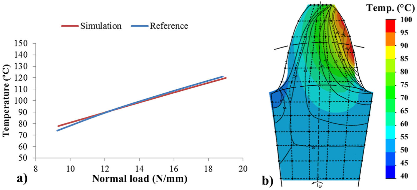
(a) Simulation results compared with those of Koffi 7 and (b) the thermal results from configuration C1 overlaid by the results from the same reference.
The results from the literature are from a similar simulation of temperature profiles and were validated with experimental analysis. The distribution of temperatures has similar values and shapes. Therefore, the simulation parameters are validated.
Configuration C1 shows a maximum temperature of 99.88°C. A distinct layer of 0.5 mm with temperatures above 90°C near the contact surface is observed. This strip of high temperatures illustrates the difficulty for the material to evacuate heat and the mechanism that causes local thermal failure. Configuration C2 shows a decrease in the total temperature. The maximum temperature is 87.7°C. Although heat direction in a tooth occurs from an active surface to an inactive surface, an important dissipation feature is observed in this configuration. An important temperature reduction occurs on the tooth root of the inactive side. Mechanically, this point is an important point of stress concentration. Although a general diminution in the temperature occurs, a high-temperature concentration exists on the active surface as the distance from the cooling hole increases in the direction of the addendum. In configuration C3, this issue is addressed, and the temperature is nearly uniformly reduced over the active face. The maximum temperature is also reduced to 82.8°C. The maximum temperature for configuration C4 is 84.04°C, which is considerably lower than the maximum temperature for configuration C2 and slightly higher than in configuration C3. Even if the tapered hole was effective in reducing the maximum temperature, it was not effective in reducing the high-temperature concentration on the active surface next to the tooth tip. Configuration C5 has a lower maximum temperature (76.33°C) with few temperature concentrations on the tooth.
Figure 12 compares the results of both cooling hole strategies and the results from the literature. 12 The tapped holes are more effective in decreasing the temperature than the normal holes, and the effectiveness increases with the number of holes. When only axial holes are used, the tapped solution had a maximum temperature that was 3.7°C lower than the solution with simple holes. With axial and radial holes, the tapped solution was 6.5°C better than when simple holes were used; the tapped holes were 76.8% more effective in this second case than in the first comparison. A comparison with the results from a similar literature experimental study of axial and radial holes 12 shows that there is difference of 1.6°C in the case of the normal axial holes. This difference can be considered to be acceptable considering the different methodologies that were employed in these studies. The difference is only 1.3°C for the case of axial and radial holes. The general trends for the same cooling strategies are the same in both studies, which corroborates our analysis.
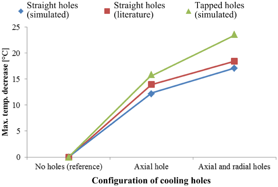
Comparison of the cooling hole strategies along with results from Düzcükoğlu. 12
Mechanical results
In a gear application, verification of the mechanical stresses is also important. These stresses will determine whether a gear can endure the static application of force or long-term fatigue. The analyses of the mechanical resistance were also performed for all tooth configurations. Two important points for the gear analysis are shown in Figure 13. Point A is the measurement of the most central element on the tooth top face. The displacement at this point is measured. It is an important number because it represents the tooth deflection that produces position errors in the transmitted movement, which is critical for precision equipment. The other analyzed point at the root; the stress is measured at point B, which is at the triple intersection between the tooth face, tooth root, and side. Tooth root failure is one of the most important failure modes in plastic gears.15,29
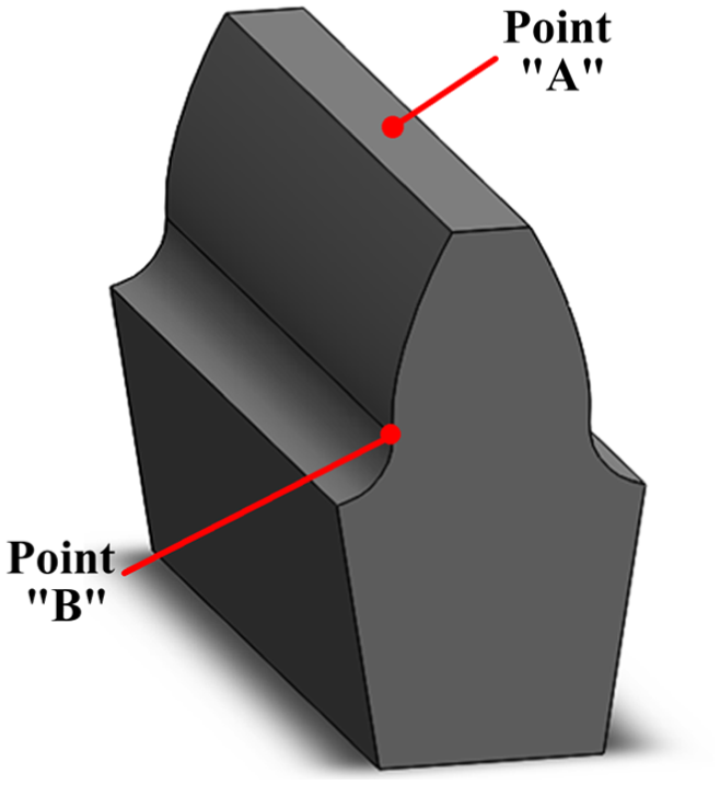
Important points on the tooth in the mechanical analysis.
The mechanical results are summarized in Table 2, and graphical representations are shown in Figure 14. All configuration stresses greater than 50% of the material limit are shown. These regions are important; at this stress level, the majority of the UHMWPE yield stress levels were achieved, which indicates local plastic deformation. This effect typically rearranges the stress distribution and reduces the local stress level by some margin. This zone remains the most sensible zone and the zone that requires special caution.
Summary of the mechanical results.


Mechanical results for configurations C1–C5 showing the stresses greater than 50% of the maximum strength and the deformation scaled by 10 times.
Configuration C1 has a small zone with a high stress concentration near the contact point. The root stress was 9.14 MPa, which represents 22.08% of the tensile strength, and the displacement at the tip was 0.1423 mm. These results are interesting considering the limitations of the plastic material. In configuration C2, the stressed zones significantly increased. They are located at the contact point; although the cooling hole weakened the tooth, high stress zones are observed. This phenomenon is evident primarily around the hole because the tooth root in the same area of the loaded side has high stress concentrations. Configuration C3 has a particularly high stress concentration at the junction of the axial hole with the radial holes. The root stress was small compared with the root stress for configuration C2. This stress redistribution can be explained by the fact that the sum of both holes created a geometry with redistributed stress concentration factors. The superior part become more flexible as the tooth tip displacement increased by 2.75% compared with the preceding configuration and increased by 62.68 compared with configuration C1.
Figure 14(d) shows the effect of the stress concentrator of the threads in configuration C4. The treads present sharp angles that substantially increase the stresses over the cooling hole. In the root, the stress increased by 162.80% when compared with configuration C1. The threaded holes also affected the tooth deflection; the tooth tip displacement increased by 9.41% compared with configuration C2.
In configuration C5, the threads are present in the types of cooling holes. As shown in Figure 14(e), this configuration had the greatest number of zones that were affected by high stresses. The root stresses marginally increased compared with configuration C4. Conversely, the tip displacement increased by 10.28% compared with configuration C3 and increased by 79.41% compared with configuration A.
Overall behavior
From the previous analysis, conflicting results are observed: A greater reduction in temperature leads to a greater loss of mechanical resistance. The correct decision choice for an application can be rather difficult. Thus, the relative loss of the mechanical properties is compared with the reduction in temperature, which is compared with configuration A. These results are depicted in Figure 15.

Trade-offs of (a) increasing stress with decreasing temperature and (b) increasing displacement with decreasing temperature.
This figure shows a trade-off comparison based on the loss on the mechanical side compared with the increase in temperature. All configurations increased the value of the stress with a decrease in temperature. Configuration C2 had the second minimum absolute increase in stress and the maximum relative stress increase due to a reduction in temperature. The root stress in this configuration increases by 12.45% for each degree Celsius saved compared with configuration C1. A lower value indicates a better cooling geometry, which causes a specific reduction in temperature with minimal loss at the mechanical level. By the same indicator, the stress increase in configuration C3 is 29.00% less than in configuration C2, which indicates that the radial cooling holes comprise an effective solution for reducing the temperature. Configuration C4 achieves a 17.45% lower stress to temperature value than configuration C2. This option is preferred to the use of a simple axial cooling hole but achieves inferior performance compared with radial cooling holes. Configuration C5 yields a stress to temperature value that is 29.59% less than that obtained for case C2. This option is the best option because the ratio increase promoted by the axial and radial holes in thermal terms by the stress increase is minimal.
Use of the displacement as the mechanical property loss yields similar results. Configuration C2 achieves a 4.79% increase in displacement with an increase in temperature. The value of this indicator is 23.36% lower in configuration C3 than in configuration C2, which confirms that the radial hole is an effective solution. Configuration C4 shows a slightly higher displacement increase with temperature compared with configuration C2; the results were improved by 3.47%. Configuration C5 had the best total performance; the value of the analyzed parameter was 29.59% less than the value of configuration C2.
These results are summarized in Figure 16, which presents the changes in the mechanical states with increasing temperature; the horizontal axis represents the results from Figure 15(a), and the vertical axis represents the results from Figure 15(b). In this figure, the farther from the origin that a configuration plots, the more the mechanical state worsens for each increase in the maximum temperature; that is, the closer to the origin, the better the trade-off that the configuration offers.

Relative changes in mechanical states with temperature compared with configuration C1.
The results in Figure 16 demonstrate that the tapped holes’ solution offers better trade-offs over the conventional cooling holes solution. Configuration C5, which uses tapped holes in both directions, provides the best trade-off. The second best option is configuration C3, which uses simple holes in both directions. The third best option is that with axial tapped holes, and configuration C2, which uses simple axial holes, provides the worst trade-off.
Conclusion
In this article, the decreased temperature and mechanical properties caused by specially made orifices on the gear tooth were analyzed and compared using numerical methods. The plastic gear meshing presents some particularities that differ from metallic meshing. Plastic gear meshing also involves an extension of the contact between the teeth outside the line of action. These particularities were added to a model to properly simulate thermo-mechanical behavior. The low modulus of the polymers has been historically considered desirable because the transmitted load is better distributed and both noise and contact forces are reduced during motion.
We analyzed the temperature and mechanical behaviors of five configurations: the original tooth, a tooth with an axial cooling hole, a tooth with axial and radial cooling holes, a tooth with a tapped axial hole, and a tooth with tapped axial and radial tapped holes.
The use of a tapped hole instead of simple cooling holes always improved the trade-off. In the case of the axial configurations (C2 and C4), the use of tapped holes improved the trade-off by 0.17 mm/°C in displacement and 2.17 MPa/°C in stress. When axial and radial holes were used (C3 and C5), the use of tapped holes instead of simple holes improved the trade-off by 0.30 mm/°C in displacement and 1.92 MPa/°C in stress. Due to their shape, the application of tapped cooling holes will benefit a plastic gear tooth by substantially decreasing the maximum operating temperature while moderately increasing the tooth deflection and only slightly increasing the maximum stress. The combination of these three factors makes teeth with tapped cooling holes the best option to increase the range of operability of plastic gears. This option also has cost benefits because it will decrease the number of required cooling holes, which reduces the machining operations for each tooth and at a large scale will likely result in substantial savings of time and money.
Footnotes
Academic Editor: Teen-Hang Meen
Declaration of conflicting interests
The author(s) declared no potential conflicts of interest with respect to the research, authorship, and/or publication of this article.
Funding
The author(s) received no financial support for the research, authorship, and/or publication of this article.