
Abstract
Methodology to enhance hydroformability of nonaxisymmetric thin-wall tubular component with variable cross sections was investigated in this study. In order to solve punch leakage problem occurred at nonaxisymmetric thin tube, the leak-resistive punch was suggested. Attaching lead at contact region of tube and punch was implemented to prevent leakage occurred due to uneven pressure distribution between punch and tube. And lead patch has also been attached at locally strain-concentrated tube surface to retard strain-concentrated necking. To validate the proposed enhancing methodology, nonaxisymmetric thin-wall tubular model part with variable cross sections has been hydroformed. The successful fabrication of model part that had previously failed during conventional hydroforming processing confirms the feasibility of proposed methodology.
Introduction
Tube hydroforming (THF) has the advantages of weight reduction, improved structural rigidity, lower tooling costs, fewer secondary operations, and reduced scrap, as compared to conventional stamping.1–3 It is important to improve sealing effect without leakage of fluid in order to give a high internal pressure in the tube. If the sealing at the ends of tube is insufficient, or the fluid inside the tube is leaking during the THF process, product having a desired shape is hard to obtain. Sealing problem can be reduced by the application of an edge expansion sealing mechanism when there is no need for feeding, and it is not easy to achieve in practical point of view. And a lot of researchers have used O-ring to improve sealing effect.4–6
In the whole hydroforming process, the loading conditions or the loading paths of internal pressure and axial feeding significantly affect the part quality. If improper loading conditions are applied, process-induced defects such as crack, wrinkling, and buckling will appear on the part. Recently, a lot of researchers have investigated loading conditions to achieve optimum process conditions.1,7–13 The results and observation from these previous studies imply that the strategic control of the loading path can be used advantageously to enhance tube hydroformability. Before fracture occurs, localized deformation (namely, necking) occurs in a small region of the tube. Material outside that region is no longer deformed once necking begins. Since bursting during THF is a consequence of prior necking, the retardation of necking is an important way to increase the overall hydroformability of a tube.14–16 The improvement in formability by decreasing the local strain gradient at potential necking points was analyzed both experimentally and by finite element (FE) simulation. 17
In this study, hydroforming of nonaxisymmetric thin-wall tubular component with variable cross sections has been investigated on the viewpoint of leakage prevention and retardation of necking. In order to solve leakage problem occurred at thin tube, one-step and two-step punches were designed and applied to estimate the performance. And uneven pressure gradient occurred at contact area between tube and punch was analyzed. As fluid leaked through weakly pressurized zone of punch, lead patch was attached at this zone. And lead patch was also attached at tube surface where intensive local strain concentration would occur to enhance hydroformability. To validate the proposed enhancing methodology, hydroforming experiment to fabricate nonaxisymmetric thin-wall tubular model part with variable cross sections has been performed in this study.
Analysis methods
Experiments
A uniaxial tensile test was performed to obtain the mechanical properties of the tube material. Tensile test specimens were machined according to ASTM E8, and standard uniaxial tension tests were conducted at a strain rate of 0.005 s−1. Tube having the material properties shown in Table 1 was used to perform hydroforming experiments.
Dimensions and material properties of test tube (SPCUD).
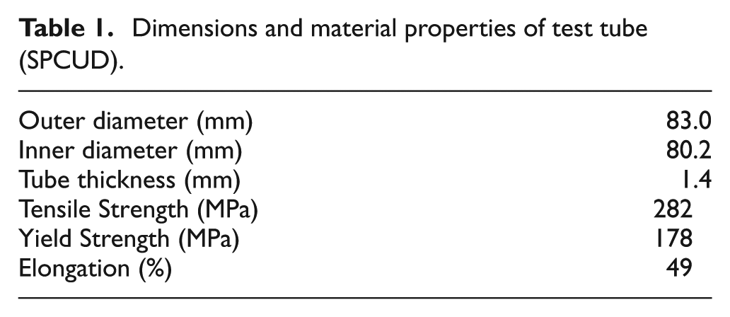
Figure 1 shows the THF machine. The experimental THF system is capable of applying pre-programmed paths of axial feed and internal pressure. It consists of two 80-ton actuators mounted horizontally to supply the axial feed at both ends of a tube. A vertical hydraulic cylinder capable of delivering a clamping force of up to 100 tons provides the upper die movement. A pressure intensifier unit with a maximum capacity of 200 MPa is used to pressurize the hydraulic fluid during the experiments. Commercially available hydraulic oil (KF2120) has been used in the experiments. Figure 2 shows dies for model part hydroforming. As shown in Figure 2, the shape of each die is nonaxisymmetric because the die cavity around a feeding axis is nonsymmetric. It also has variable cross sections.
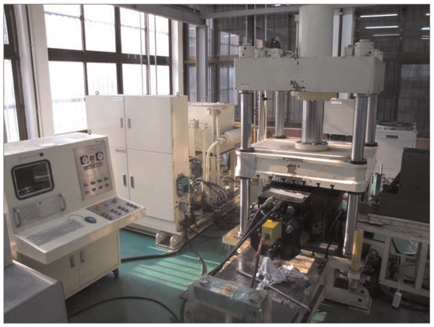
Hydroforming machine.

Hydroforming dies for nonaxisymmetric model part: (a) upper and (b) lower dies.
FE analysis
To characterize hydroforming process for complex and nonaxisymmetric thin-wall tubular component with variable cross sections, FE analysis has been performed using commercially available FE code, FORGE™. The die was regarded as a rigid body, and a three-dimensional (3D) model was used. Table 2 gives analysis conditions for FE analysis. Figure 3(a) shows the initial configurations for FE analysis of hydroforming process. Hydroformed shape of model part which is tubular component with variable cross sections is shown in Figure 3(b).
Analysis condition for FEM.

FEM: finite element method.

(a) FE analysis model and (b) model part.
Results and discussions
Punch design
To investigate the effect of punch geometry on sealing, THF is conducted using one-step and two-step punches. The tube is positioned in the die and sealed at the ends by the axial feeding punch.
Sealing is important to give a high internal pressure in the tube. Conventionally, multi-step punch has been used to improve sealing effect in the hydroforming experiment. In case of two-step punch, tube is formed as step at the edge of the tube and tube end portion contacts cross section of punch as well as side section of punch as shown in Figure 4(b). This phenomenon improves sealing effect. However, in case of thin tube, it expects that defects occur at the end of the tube due to lack of force to sustain. So, hydroforming experiments were performed to check the performance of respective punch shapes. Figure 5 shows edges of hydroformed tubes for respective punch shapes. As shown in this figure, tube edge hydroformed by one-step punch shows sound shape without any defective flows, while two-step punch shows irregular end shapes.

Schematic drawings of cross section of punch: (a) one-step punch and (b) two-step punch.

Edges of hydroformed tubes: (a) one-step punch and (b) two-step punch.
Because the contact area of two-step punch is divided into two zones, the ability to sustain axial force is relatively lower for thin tube. So, the susceptibility of defects increases at the end of the tube. However, defects do not occur when using one-step punch. The increased sustaining force due to the increase in contact area enhances leakage prevention effect for thin tube. Figure 6 compares the internal pressures in accordance with one-step punch and two-step punches. It can be identified that internal pressure is approximately 13 MPa higher when one-step punch is used. The increased leakage in two-step punch is the main cause of lowered internal pressure. Therefore, using one-step punch can be more advantageous for thin tube in the hydroforming process, as is 1.4 mm tube thickness in this study.

Comparison of internal pressure between one-step and two-step punches.
Leakage prevention
When the model part is complex and nonaxisymmetric, uneven pressure gradient can be generated on contact surface between tube and punch. Therefore, fluid would leak into weakly pressurized region of punch. In order to analyze the sealing problems caused by the complex shape, FE analysis was performed.
Figure 7 shows normal stress distributions on one-step punch. As shown in Figure 8, stresses of 64.5, 97.4, 19.8, 97.9, and 65.0 MPa were generated in the regions of A, B, C, D, and E on punch, respectively. In this case, leakage can be occurred in low-stress regions of A, C, and E.

FE analysis result of stress distributions occurred on one-step punch.

Stress distribution on punch of complex die.
In order to solve leakage problem caused by nonuniform pressure distribution, lead patch was attached to the punch as shown in Figure 9. Before hydroforming started, lead patch was attached to the contact zone between tube and punch as shown in Figure 9. Incompressible lead patch would prevent fluid from leaking on weakly pressurized region of punch caused by nonuniform pressure distribution.

Attaching lead patch to the punch.
Figure 10 compares the variations of internal pressures in accordance with the presence and absence of lead patch attached to the punch. It can be identified that internal fluid pressure is approximately 10 MPa higher when the lead patch is attached to the punch as shown in Figure 10. Therefore, attaching lead patch to the punch is proved to be effective method to improve sealing ability occurred on complex and nonaxisymmetric THF.
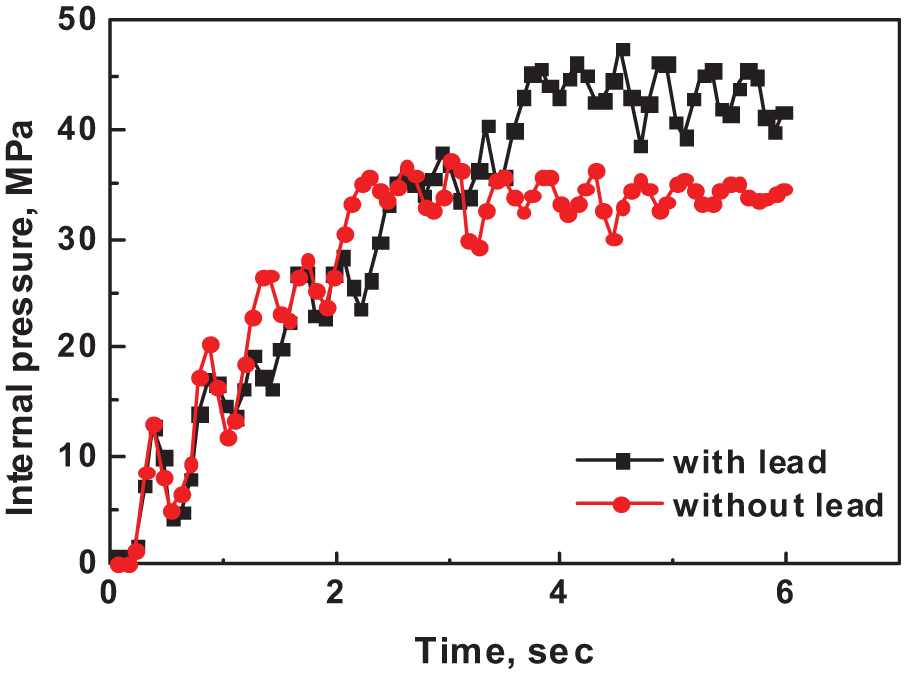
Comparison of internal pressure between punch with and without lead patch.
Restrictive hydroforming to release local strain concentration
Since the bursting in THF process is the consequence of necking, retardation of necking initiation is important in enhancing the hydroformability. As high strain gradient will be established at necking point, the decrease in local strain gradient is an effective way to retard necking initiation. Therefore, in this study, the expansion at potential necking point has been intentionally restricted by lead patch to reduce strain gradient at potential necking point. 17
Figure 11 schematically compares the principle of restrictive hydroforming with nonrestricted conventional hydroforming. Prior to the hydroforming, an incompressible material (lead) is attached to the tube where the strain-concentrated zone would contact. Due to the incompressibility of lead, the tube expansion is locally restricted, and the resultant strain extends to adjacent regions of the tube during hydroforming. After the first stage of hydroforming, the lead is removed from the tube, and the tube is hydroformed again to obtain the targeted shape without the local restriction.

Schematic drawing of hydroforming test: (a) nonrestricted and (b) restricted by lead patch.
FE simulation results for the restrictive preforming show significant reduction in strain concentration. Nonrestricted tube shows 47.7% maximum strain at the strain concentration region, while the maximum is reduced to 31.8% after the restricted preforming. The decreased local strain gradient at the strain concentration region, due to the prestraining effect during the restrictive preforming, enhanced the formability. Figure 12 compares thickness variation between restricted tube and nonrestricted tube. As shown in this figure, the restrictively hydroformed tube using lead patch shows more uniform thickness profile.
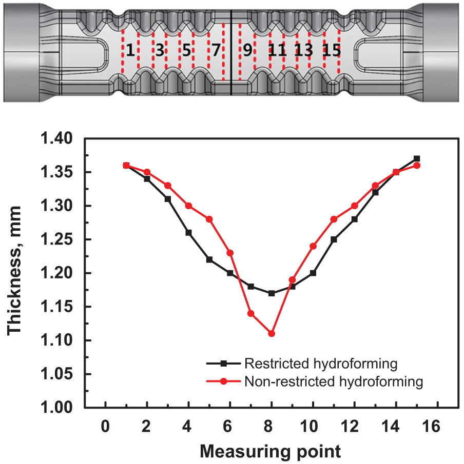
Comparison of thickness variation between preformed hydroforming and nonpreformed hydroforming.
For the verification purpose, hydroforming experiments have been performed. Figure 13(a) shows lead patch attached at potential necking point. Attaching a lead patch on the tube surface that will contact with strain-concentrated zone locally restricts tube expansion and the resultant strain be extended to adjacent zone during hydroforming. Figure 13(b) shows hydroformed tube without any process-induced defects.

Hydroforming experiments: (a) attaching lead patch and (b) hydroforming test.
Conclusion
Methodology to enhance hydroformability of complex tubular component with variable cross sections has been investigated and the following conclusions are obtained:
In solving punch leakage problem occurred at nonaxisymmetric thin tube, the use of one-step punch can be one of the good alternatives;
Attaching lead at contact region of tube and punch was effective to prevent leakage occurred due to uneven pressure distribution between punch and tube;
Lead patch attached at locally strain-concentrated tube surface retards strain-concentrated necking;
The successful fabrication of nonaxisymmetric thin-wall part that had previously failed during conventional hydroforming confirms the feasibility of proposed methodology.
Footnotes
Academic Editor: Pedro AR Rosa
Declaration of conflicting interests
The author(s) declared no potential conflicts of interest with respect to the research, authorship, and/or publication of this article.
Funding
This work was supported by the National Research Foundation of Korea (NRF) grant funded by the Korean government (MSIP) (no. 2012R1A5A1048294).