
Abstract
Robust performance is the most important concern in the design of any product, especially in system design stage that precedes parameter design, because it actually determines the attainable level of product robustness in the parameter design phase. In this article, a framework of modelling and analysis of system robustness is proposed, which includes system modelling, cluster analysis and design of experiments. In the process of system modelling, the metamodel of general design theory was utilized to describe the function–structure model of product design, and the customer needs are transformed into functional requirements. Based on the independent axiom and zigzag mapping mode of axiomatic design, the functional requirements are mapping to design parameters, and the design matrix is created, which is then converted into design structure matrix by identifying the relationship between functional requirements and the sensitivity of functional requirements to design parameters. The fuzzy clustering algorithm is utilized to cluster the design parameters and to group the system components into modules in design structure matrix, and the interface among modules can be identified and system robustness incidence matrix is developed. Then the incidence parameters are considered as controllable factors, and experimental design techniques are utilized to analyse the influence of incidence parameters on the design objectives, if any, that may result in a robust system. The proposed framework is illustrated with the trolley design of overhead travelling crane.
Introduction
In the early phase of product design, it is very important to enhance the design efficiency for the shorter time of the production and the lower cost. Increasing the robustness of the product system design can reduce mistakes of the whole product life cycle, so that it can largely improve the quality of the design. The design decisions of the system design phase have great influence on the product design progress. In addition, the designers hope to learn and analyse the interaction relationships among the product design factors as soon as possible, so as to minimize the change in the later design phase and enhance the robustness of the product design.
Robust design is a method for improving the quality of a product through minimizing the effect of the causes of variation without eliminating the causes. Under the notion of robust design, a good design is defined as the one that not only maximizes performance but also is ‘less sensitive’ to variation in uncontrollable design parameters (DPs). Taguchi 1 design method divides the design process into three stages called system design, parameter design and tolerance design. System design is a process of applying scientific and engineering knowledge to produce a basic functional prototype design. 2 The initial design may be functional, but it may be far from optimal in terms of quality and cost. The purpose of parameter design is to find the values of the ‘control parameters’ for which performance is insensitive to variations in the values of the uncontrollable ‘noise variables’. Tolerance design is concerned with how much variation in the design and noise factors is permissible. However, most methods of the robust design put emphasis on parameter design and tolerance design as the most important means of satisfying robust technical systems, which is based on the experimental design and is difficult to be applied to system phase, such as Sii et al., 3 Cheng and Lin 4 and Liu et al. 5
Although Taguchi 6 acknowledges that ‘system design is extremely important’, he down-rates the choices made by the designers as to what systems to select and study, by referring to them as mere ‘gut-feeling’. Andersson 7 argued that system design actually determines the attainable level of product robustness in the parameter design stage. In order to enhance the design robustness of product design, it is essential to consider utilizing robust design method in the system design phase. The design process can be verified in early design period. The quantitative effect of downstream constraints can be considered before the DPs are determined and the adaptability of product design can be improved to avoid great redesign.
A system is considered robust when its functional performance is insensitive to selected DPs and environmental changes, while satisfying design and customer requirements. Zakarian et al. 8 presented a framework for robust system development based on system modelling, integration analysis and quality engineering techniques, and discussion on the importance of system modelling and traditional robust design procedures and on the difficulties associated with the development of robust systems. Lu and Li 9 proposed a hybrid model–based robust design method to handle model uncertainty using the matrix perturbation theory. Lu et al. 10 proposed a robust design approach to design the robustness of the nonlinear system under large uncontrollable variation-based variable sensitivity. Zhang et al. 11 proposed a model of describing relationships among functional requirements (FRs) and structural characteristics, DPs and uncontrollable factors in the nonlinear systems. In the system design stage of the product, the majority of the design information is uncertain, so it is difficult to describe the traditional robustness model based on the statistics.
To increase the flexibility of the product design, the conventional robust design may be effectively integrated with the concept of axiomatic design. By combining the basic concept of robust design with axiomatic design, high-quality products with a low cost can be produced while maximizing market leverage. 12 According to Suh, 13 a design that maintains the independence of FRs is an ideal design, and an uncoupled design and a decoupled design are more robust than a coupled design. The independence axiom can be used as an approximate decoupling criterion to decouple the coupled design. Xiao and Cheng 14 discussed the relationship between axiomatic design and robust design and revealed their consistency. Cheng 15 used independence axiom to represent system structure and capture design requirements and presented independent axiom-based robust design method for nonlinear system. Cheng et al. 16 proposed a novel analytical robust design methodology based on axiomatic design principles.
This article presents a method of modelling and analysis of system robustness for product design. Axiomatic design is utilized as framework, and the FRs are classified into basic FRs, expectable FRs and adjunctive FRs based on Kano model, and their concepts are defined. The experimental design is used to analyse the robustness. The remainder of the article is organized as follows. The FRs of product design are analysed in section ‘FR analysis of product design’. In section ‘Analysis process of system robustness’, the analysis process of the mechanic system robustness is given. The experimental design and robust system analysis method is presented in section ‘Experimental design and robustness analysis’, followed by a detailed application of this methodology in section ‘Case study’. The article ends with conclusions in section ‘Conclusion’.
FR analysis of product design
The primary work of robustness analysis for mechanical system is accurate to obtain and describe the product need information. The FR modelling is based on the customer demands’ analysis. The customer demands are usually concerned with the aspects such as using function, property, appearance and price, which cannot be directly transformed into the product structure information that requires to be transformed into the FRs in advance. In the process of the product development, only the FR information is sufficiently learned and described, and then they are mapped into the physical structure (or DPs); the product concept model established by the FR analysis can be to the latter design of product. Once the product design is finished, it should possess some specific FRs. The needs of the customers to one certain product are because of the requirement for its function.
Considering the relationship between customer needs (CNs) and product quality characteristics, the FRs for product design are classified into basic FRs, expectable FRs and adjunctive FRs based on the model of customer satisfaction, as shown in Figure 1.

Functional requirement classification of product design.
For the customers, the basic FRs are indispensable for one product. If the product does not have such functions or these functions are good enough, it will cause the customers strong dissatisfaction. When the product has these functions, the customers’ complaints can be eliminated, but the customers’ satisfaction degree is not increased, such as the hoisting function of the crane. The expectable FRs are those the customers expect, but not necessary. The more the expectable FRs of the products, the larger the customers’ satisfaction degree, such as the speed regulation of the crane which is what the majority of the users expected. The adjunctive FRs provide some fully unexpected product attributes to the customer, which may give a pleasant surprise to the customers, such as the early warning of the crane operating under the abnormal condition which is beyond what the users expect from the FRs.
Yoshikawa 17 presents a kind of concept description model on design process pattern called general design theory (GDT). GDT regards the design as the mapping process from function space to attribute space and uses metal model and metal model space to express the progressive mapping process. The metal model uses a set of attribute to describe the design process state, structures and their correlation and dependence of the design object. To better express the function–structure model of product design–based GDT, some concepts and terms need to be redefined.
Definition 1
The abstract description of function property for design object is called as the function concept, which is denoted as FC. The set of all FCs is called as function concept space, which is denoted as FCS.
Definition 2
The abstract description of structure characteristics for design object is called as the structure concept, which is denoted as SC. The set of all SCs is called as structure concept space, which is denoted as SCS.
Definition 3
The FC that is to meet the design environment and realize basic FRs is called as basic function concept, which is denoted as BFC. The set of all BFCs is called basic function concept space, which is denoted as BFCS, and
Definition 4
The FC that is to meet the expectable FRs is called as expectable function concept, which is denoted as EFC. The set of all EFCs is called as the expectable function concept space, which is denoted as EFCS, and
Definition 5
The FC that provides some fully unexpected product attributes to the customer is called as adjunctive function concept, which is denoted as AFC. The set of all AFCs is called as the adjunctive function concept space, which is denoted as AFCS, and
Definition 6
The SC that can realize the basic FRs and meet the constraints is called as the basic structure concept, which is denoted as BSC. The set of all BSCs is called as the basic structure concept space, which is denoted as BSCS, and
Since the customers’ need characteristics are dynamic factors, they may be changed with time, technology and market segmentation. The FRs reflect different hierarchy CNs for product functions; therefore, they will move downwards in model with the development of time. The expectable FRs may be converted into basic FRs, such as the Internet function for mobile phone.
The definition and description of the above concepts are aimed to analyse well the product system robustness. The basic FRs of any products must be well satisfied first and then the expected function requirements and the adjunctive FRs are considered. In addition, except the influence on the BSCs, the basic FRs should not change with the other SCs. The basic structure must be insensitive to the change in the expectable FRs and the adjunctive FRs. They may be easily expressed as


Analysis process of system robustness
The product structure is a kind of physical domain to achieve the FRs in product design process, so it is fundamental to acquire the precise and complete information structure information to respond to the CNs. Although the GDT can express design process that is translated from function space into attribute space, for the complex product, the abstract SC is difficult to determine in mapping process, and the hierarchy and relationship are not clear enough. 18 The axiomatic design approach views the design process as a series of mappings among customer, functional, physical and process domains. Every domain is characterized by its element, namely, CNs, FRs, DPs and process variables (PVs). As the design progresses, broad, high-level requirements are decomposed into smaller sub-requirements, which are then satisfied by sub-solutions. As the designers select solutions, they use the two design axioms to evaluate the quality of the solutions. Thus, axiomatic design provides guidance about how to make good decisions and enhance the design robustness.
According to axiomatic design, the FRs of the product are mapped into the product structures, and then the concept structures of the product are identified, named DPs. Combined with the experience knowledge, the designers can judge whether the FRs’ decomposition and DPs’ choice meet the design requirement or not, and whether it can get a satisfying result. Then the connection relationships among the concept structures are analysed, the design structure matrix (DSM) is constructed and the coupling modules are identified. The detail procedure of design process is given as follows:
According to the design tasks, design purpose and company-itself conditions, the CNs of the product are determined first. The experts and designers come up with all the FCs by analysing the CNs and form the FCS. In the FCS, the basic functions satisfying the technical requirements and the constraints are selected to make up the BFCS, which can be expressed as
According to previously defined FC and technical requirements, we can choose physical structures satisfying the corresponding FRs from knowledge base and the designer’s brain and build the SCS. The mapping process between FCS and SCS should be done with decomposition by zigzagging mapping. Simultaneously, the reasonable relationship between them should be fully considered to satisfy the independence axiom as possible. Because the coupling is difficult to avoid in some products’ design, the partial coupling may remain, or the systematic inventive thinking (SIT) and TRIZ are used to decoupling. If the coupling of DPs is very strong, they can be clustered to a coupling modular, and then the relationship between the coupling modules is analysed.
In SCS, the DPs satisfying basic FRs and the constraints are chosen and combined with BSCS, which is defined as
According to the mapping between FRs and physical structures, the design matrix of the product can be built. The design matrix should be rearranged to make it the diagonal matrix or lower triangular matrix, and then it is transformed into the DSM. 19 Any row in DSM represents the influences of other DPs on the DP in corresponding row. Any column in DSM expresses the dependences of other DPs on the DP in corresponding column. The DSM can be divided into two parts. One is the DPs of BSCS and another is other DPs, as shown in Figure 2.
Make reconfiguration DSM. The DPs of BSCS are considered as the core and the clustering algorithm is used. Due to the characteristics of the DSM, we choose the fuzzy clustering algorithm to do the calculation. According to the concept of the fuzzy matrix, the only binary value ‘0’ and ‘1’ cannot fully convey the relevance between the DPs. So we use a 5-point scale (0, 0.25, 0.5, 0.75 and 1) to describe strengths of relationships between DPs. By this way, we can cluster the matrix by the following steps:
Step 1: The relationships between DPs are further determined according to the designers’ experience and analysis. And then the original parameter matrix is obtained by adding the relevance between the DPs

where xij means relevancy influence between the different DPs and the value present as follows: 0, no influence between the DPs; 0.25, little influence between the DPs; 0.5, large influence between the DPs; 0.75, great influence between the DPs and 1, direct influence between the DPs or the DPs themselves.
Step 2: Build the fuzzy similarity matrix

where
Step 3: Rebuild the


Step 4: According to the Lambda-max method, 20 we will initially get the threshold λ and then adopt the λ-cut matrix to do the clustering with the former matrix

where

Design structure matrix.
Using the above steps, the clustering block can be acquired. They may be coupling modules or a set of some independent parameters. Therefore, the system structure will be divided into several mutual coupling modules which have small degree of dependency, so that the system has the strong robustness. According to the axiomatic design theory, the design satisfying two axioms is more robust, and the design with weak coupling is more robust. So, the reconfigurable DSM can be defined as the system robustness relationship matrix, as shown in Figure 3.

System robustness relationship matrix.
Experimental design and robustness analysis
The system robustness relationship matrix based on the GDT and axiomatic design is a kind of coupling design scheme with weak interaction and dependence. Each clustering modular in matrix can be regarded as a subsystem, component or substructure. The element outside the clustering module is considered an interface when it does not allow the decomposition of the modular–modular interaction matrix into mutually separable clusters. Each interface entry DP(i, j) in the system robustness relationship matrix represents an interaction between product subsystems; therefore, system robustness is influenced. For example, entry DP(6, 2) in Figure 3 denotes an interaction between modules 1 and 2 through DP6 and DP2. It indicates that module 1 has influence on module 2. More specifically, DP2 in module 1 affects DP6 in module 2. If DP2 has variation, DP6 will change accordingly. So, entry DP(i, j) represents the influence of DP j on DP i . In other words, the modular where DP i is in is dependent on the modular where DP j is in.
The system robustness relationship matrix identifies all the interfaces between modules. In system robustness analysis, these interfaces are used as controllable factors in parameter design experiments to identify whether levels exist that result in robust system performance. Therefore, each entry DP(i, j) in the matrix in Figure 3 becomes a controllable factor in a parameter design. For most of the practical project problems, there is generally no specific formula used to represent the relationship between interaction parameters and system response, as well as the constraints. Thus, the experiment or numerical simulation is used. Not only numerical simulation but also design experiment needs much time. So, the robust design needs some proper samples, experiments or simulations to fit system response functions, in order to establish surrogate model. The premise of setting up surrogate model is that there are enough sample statistics; however, the sample points should be selected by design of experiments and can reflect design space feature as widely as possible, such as orthogonal experimental design, full factorial design, central composite design, Latin square design and Box–Behnken design (BBD). Taguchi structured his testing around the use of orthogonal arrays. The orthogonality or independence provides an efficient test method for the concurrent testing of multiple parameters. An orthogonal array of statistical design provides a geometrically balanced coverage of the experimental region.
For the system robustness relationship matrix of Figure 3, three interactions remain outside the clustering module, DP(6, 2), DP(10, 6) and DP(11, 4), which are specifically DP2, DP6 and DP4, respectively. These three interactions, because they express interfaces between the robustness matrix subsystems, are central to attempts to achieve robust system design. For this reason, these interactions are given their own designation as interface entries in the robustness matrix and are the focus of subsequent experimentation. They are considered as controllable factors, each one being of three levels. Based on these assumptions, the orthogonal array L9(34) for controllable factors can be chosen. There are nine different level combinations, as shown in Table 1.
Orthogonal array and factor assignment.

DP: design parameter.
For the simple product design, the orthogonal experiment and visual analysis or technique of variance analysis (analysis of variance (ANOVA)) may be used to identify the contribution of each interface entry to design objectives and to determine the principal interface entries and ignore those with small influence. For the interface entry with big effect on design objectives, it is necessary to control and adjust it, in order to enhance the system robustness. For the complex product design needing accurate analysis on relationship between the respond and DPs, the surrogate mode can be applied, such as response surface model and Kriging model. Kriging model has advantages such as unbiased estimator at the training sample point, desirably strong nonlinear approximating ability and flexible parameter selection of the model, and thus, it is quite suitable for approximate models.
Case study
The overhead travelling crane is a kind of important industrial production equipment and is widely used in industrial and mining enterprises, railway transportation, port and so on. It is complex in work condition, changeable in loading character and large in calculated amount. The traditional design method of the crane is generally single and small batch design mode, and excessive reliance on experienced designers, which do not quickly respond to the needs of individual customers at low cost. To improve the adaptability of the crane design, the system robustness should be considered in the early phase. In this article, the crab (trolley) of the overhead travelling crane is designed, and its robustness is analysed. The design process is described as follows:
1. Design needs. The crane is applied in the power plant and is not used often. Generally, it lifts medium load, but it occasionally lifts large loads. Two trolleys are required to coordinate. The loading capacity of the main trolley is 32 ton, which is for the break bulk cargo. In addition, the span is 31.5 m and lifting height is 22 m. The main customer requirements for the trolley are shown in Table 2.
Main customer requirements for the trolley.

2. According to the analysis of the CNs and current market demands, the designers may create all FCs and establish FCS. The major task for the crane is to lift and then to expand its working scope and enhance its speed and efficiency in a safe way. Based on axiomatic design, the FRs and DPs of brake are decomposed according to zigzagging mapping, as shown in Tables 3 and 4. Every level needs independent functional analysis in decomposable process. For the system design, the specific parameter has not been explained in the process of decomposition. For example, the specification and type of electric motor, brake and reducer are not mentioned.
Functional requirements’ decomposition of the trolley.

FR: functional requirement.
Design parameters’ hierarch of the trolley.

DP: design parameter.
3. The design matrix is established according to the relationship between FRs and DPs in every level, which is rearranged as shown in Figure 4. What is more, the basic FRs are marked as b, the expected FRs are marked as e and the additional FRs are marked as a in the column of FRs. That is (FR111, FR112, FR113, FR121, FR122, FR123, FR124, FR211, FR212, FR213, FR221, FR222, FR31, FR32) ∈ BFCS, (FR114, FR115, FR214, FR215, FR32, FR41, FR42, FR43, FR45) ∈ EFCS and (FR223, FR46, FR47, FR48) ∈ AFCS.

Rearranged design matrix of the trolley.
4. The design matrix of the trolley should be converted into the DSM. Then the DSM is reconstructed by concerning relationship among all the physical structures of DPs. After that, according to step 1 in section ‘Analysis process of system robustness’, the interactions should be quantified to describe strengths of relationships between DPs. The quantification can be different for the design problems. In this article, a 5-point scale (0, 0.25, 0.5, 0.75 and 1) based on the functional and structural interface relationships analysis is introduced. After the interactions have been quantified, the original fuzzy parameter matrix can build as shown in Figure 5.
Original fuzzy parameter matrix.
When we have built the original parameter matrix, the calculation can be done according to step 2 to get the fuzzy similarity matrix, as shown in Figure 6.
Fuzzy similarity matrix.
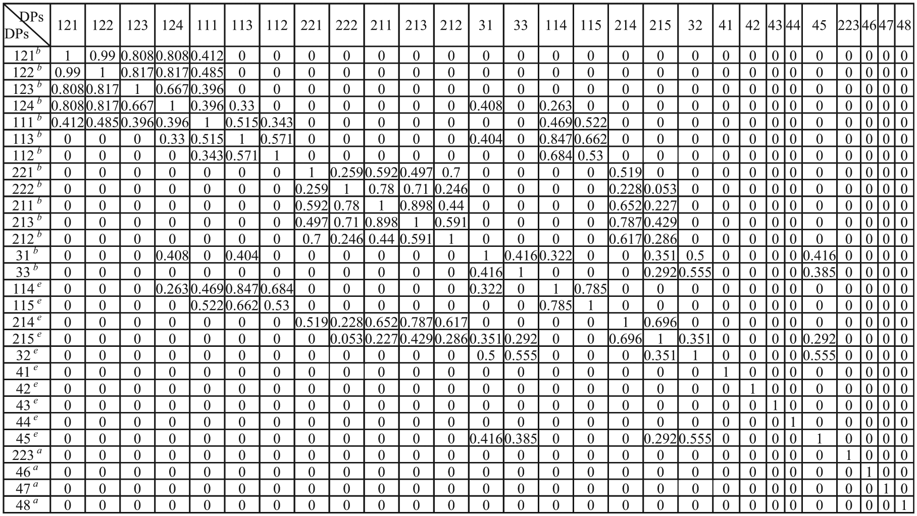
After the fuzzy similarity matrix has been obtained, the calculation can be done according to step 3 to get the fuzzy equivalence matrix, as shown in Figure 7.

Fuzzy equivalence matrix.
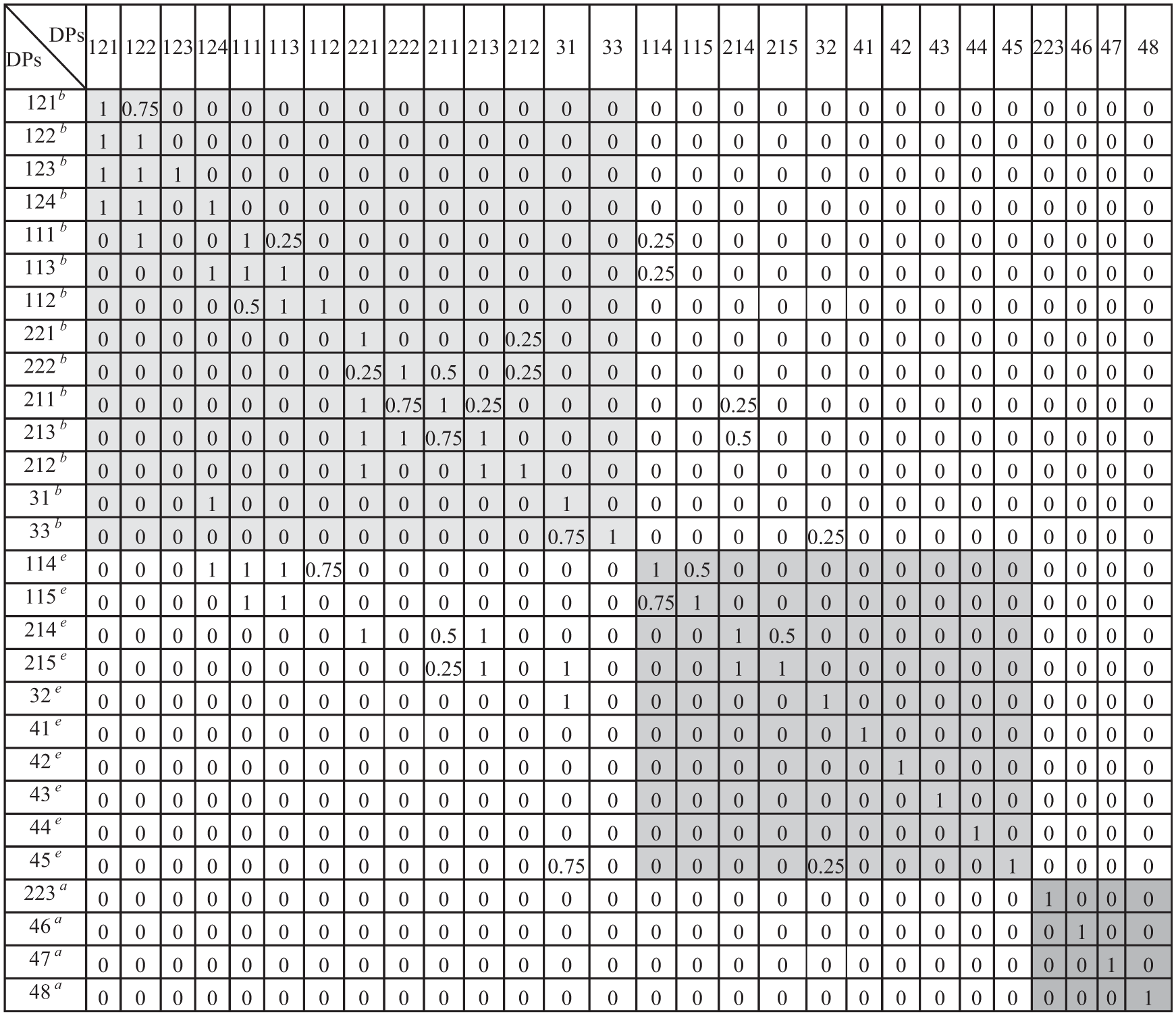
When all the above steps are done, we will get thresholdλ = 0.5 by calculation and then use this threshold λ to get the λ-cut matrix, then cluster the matrix by the result of λ-cut matrix and rearrange it. The fuzzy equivalence cluster matrix after re-arrange is shown in Figure 8.

Fuzzy equivalence cluster matrix after re-arrange.
Because the values in the fuzzy equivalence cluster matrix do not strictly mean the relevance between the parameters, it is only used to cluster the matrix. So we must recover the value in the original fuzzy parameter matrix to get the interaction between cluster clocks. In Figure 5, the scale 0.75 and 1 means strong relevance, so we replace ‘0.75’ with ‘1’ and substitute ‘0’ for other values in the matrix. By this way, the system robustness relationship matrix is acquired by clustering analysis as shown in Figure 9.

System robustness relationship matrix of the trolley.
5. The influence analysis of incidence parameters. From Figure 7, it can be seen that in the system robust relationship matrix, DP(111, 122), DP(113, 124), DP(114, 124), DP(31, 124) and DP(215, 31) are elements outside the module. Their variation will cause the change in DPs for corresponding module, so they are the main factors influencing the system robustness. Especially, DP124 (drum) affects multiple modules. Its diameter size affects torque and transmission ratio, and its length affects the width of the trolley frame. The latter will cause the change in track centre of the trolley, and then it will affect the length of compensation shaft. The diameter and the length of the drum are not independent of each other, and the length is decided by the diameter.
In addition, the wheel group of the trolley is influenced by the parts of hoisting mechanism, but the influence of each individual piece on the wheel group is small. So, the above incidence parameters outside the module are considered as the controllable factors to analyse the system robustness and the degree of their influence on the clustering module is identified. There are three controllable factors DP122, DP124 and DP31, and they are marked as A, B and C, respectively. Since the diameter of the drum is determined by the diameter of wire rope and rope diameter ratio, its value has certain specification. According to the working conditions of this crane, each controllable factor is arranged in three levels. For the relationship between incidence parameters, the response is linear and their levels are strict; the orthogonal experimental design can be chosen, as shown in Table 5.
Level of incidence parameters for the trolley.

6. The goal of experimental design is to ensure that the size and weight of the trolley are, respectively, small and light. The size of the trolley mainly includes the size of the trolley frame, overall height of the trolley and track centre. The increase in track centre will make the weight of end carriage of bridge heavy. The overall height of the trolley mainly affects large-scale cranes. In the case of the trolley, where the cranes are about medium- and small-sized, the influence of the overall height is not considered. The size of the trolley frame may affect the weight of the trolley, and it can be classified into the objective of the weight. So, this article selects the weight of the trolley and track centre as design objectives, in order to analyse the influence degree of the changes in incidence parameter on the target. The experimental design is arranged and the experimental array L9(34) is chosen. The results of the experimental design are shown in Table 6.
Results of the experimental design and visual analysis.

7. Because the number of the incidence parameters is less and relationship with the response is approximately linear, visual analysis of the experimental design results is applied to determine the influence of controllable factors on design objectives, as shown in Table 6. The larger the range of the level value, the greater the influence of the factor on design objective y, and the bigger the importance of the factor. It can be seen from Table 6 that the influence of the drum diameter on two design objectives is the largest, the influence of the bogie frame is the second largest and the hook assembly only slightly affects the weight of the trolley.
Furthermore, ANOVA is performed from the results of experiments. The significance of the incidence parameters for the different responses was assessed through the ANOVA tables presented in Tables 7 and 8, by comparing the results of the contribution rate. Furthermore, for objective y1, the contribution of the drum is up to 96%, which illustrates that the variation in the drum may result in obvious change in y1. For objective y2, the contributions of three factors are, respectively, 7.17%, 53.87% and 28.46%. However, the overall effects are not large, because the weight of the trolley is related to all the DPs and is not mainly determined by the three factors. But their effect on the production cost is relatively large, because the increase in the drum diameter may make the reducer bigger, although the length is shorten, which may make the track centre and end carriage smaller. Since the influence of the change in the drum diameter on two objectives is different, the drum diameter is set to 450 mm by overall consideration. The other two incidence parameters can be considered as adjustable parameters to adapt the CNs, so that the trolley system has stronger robustness.
ANOVA table relative to track centre.

DoF: degree of freedom.
ANOVA table relative to weight.
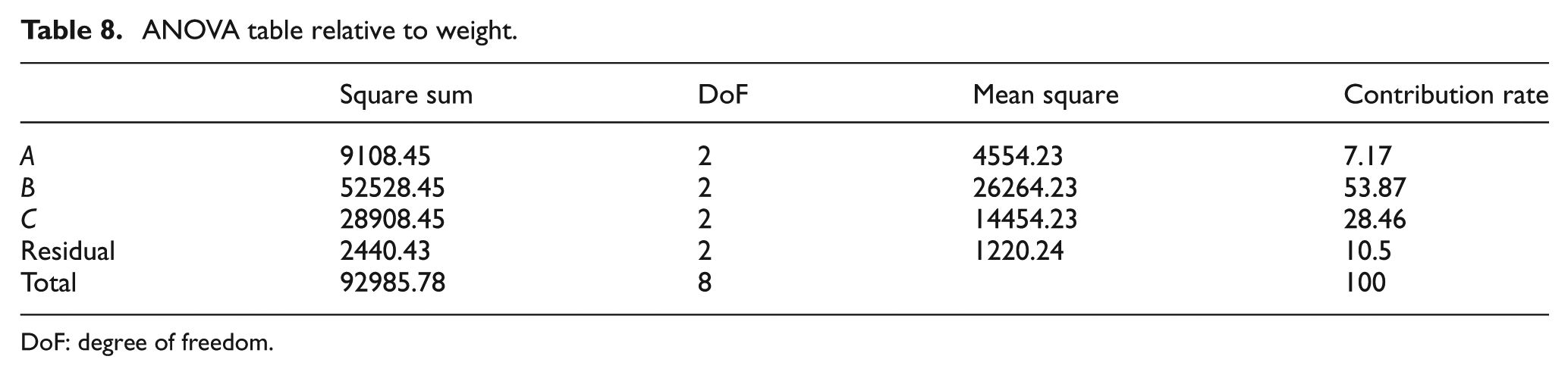
DoF: degree of freedom.
Conclusion
The system design actually determines the attainable level of product robustness in the parameter design stage. In this article, a frame based on system modelling, cluster analysis and design of experiments for the development of robust system was proposed. From the view of CNs, the FRs were classified into basic FRs, expectable FRs and adjunctive FRs. The metamodel of GDT was utilized to describe the function–structure model of product design, and some concepts and terms are redefined. Axiomatic design theory was applied to zigzagging mapping between FRs and DPs. The DPs satisfying basic FRs and the constraints were separately divided and combined into BSCS. The design matrix was rearranged to make it the diagonal matrix or lower triangular matrix and then it is transformed into the DSM. Then the DSM was reconfigured. The DPs of BSCS were considered as the core, and the clustering algorithm was used to acquire the clustering module with small dependency. The element outside the clustering module was considered an interface, and these interfaces were used as controllable factors in parameter design experiments to identify whether levels exist that result in robust system performance. The orthogonal experiment was used to identify the contribution of each interface entry to design objectives and to determine the principal interface entries and ignore those with small influence, so that the system has strong robustness. Finally, the trolley of the overhead travelling crane was designed, and its robustness was analysed.
Footnotes
Acknowledgements
The authors would like to thank the reviewers for their valuable comments and suggestions.
Academic Editor: Yong Chen
Declaration of conflicting interests
The author(s) declared no potential conflicts of interest with respect to the research, authorship and/or publication of this article.
Funding
This work was supported by the National Natural Science Foundation of China under the Grant Nos 51165007 and 71462007.