
Abstract
This study proposed a dynamic parameters’ identification method for the feeding system of computer numerical control machine tools based on internal sensor. A simplified control model and linear identification model of the feeding system were established, in which the input and output signals are from sensors embedded in computer numerical control machine tools, and the dynamic parameters of the feeding system, including the equivalent inertia, equivalent damping, worktable damping, and the overall stiffness of the mechanical system, were solved by the least square method. Using the high-order Taylor expansion, the nonlinear Stribeck friction model was linearized and the parameters of the Stribeck friction model were obtained by the same way. To verify the validity and effectiveness of the identification method, identification experiments, circular motion testing, and simulations were conducted. The results obtained were stable and suggested that inertia and damping identification experiments converged fast. Stiffness identification experiments showed some deviation from simulation due to the influences of geometric error and nonlinear of stiffness. However, the identification results were still of reference significance and the method is convenient, effective, and suited for industrial condition.
Introduction
High speed and high precision are the important development directions of computer numerical control (CNC) machines. However, accuracy and stability problems arise because of the increase in the rotating speed of the spindle and the feeding speed of servo system. High feed rate means the enlargement of the system tracking error. To reduce the tracking error and improve the machining accuracy of the machine tools, researchers have taken some measures on the controller of the machine tool, such as improving the position and speed gains of the machine controller and using the feedforwards of speed or acceleration.1,2 However, the high-gain parameters affect the stability of the control system. In addition, the stability problem of high-speed cutting, that is, the cutting instability (such as chatter) in the processing process in the case of large cut depth, high rotation speed of the spindle, and high feeding speed condition, often plagues the researchers and users. To solve the problems, it is needed to conduct system parameter identification and accurate dynamics modeling for the feed system of the CNC machine tools.
The parameter identification and modeling of the servo system have been repeatedly researched. Under the open-loop control condition of the motor, Kaan Erkorkmaz and Altintas 3 identified the dynamic parameters of the worktable, including inertia, damping, and Coulomb friction, using unbiased least square algorithm. Chyun-Chau Fuh and Tsai 4 proposed an identification method for the dynamic parameter of the servo system using the continuous and disordered signals with fixed band width as drive signals. The test proved that the method effectively avoided the disturbance of the uncertain high-frequency signals and presented convergent identification results. Varanasi and Nayfeh 5 drove the system using the sinusoidal signal generated by the signal generator. On the basis of analyzing the amplitude–frequency characteristics of the input and output signals, the frequency-response function of the system was obtained. Pislaru et al. 6 from the University of Huddersfield in the United Kingdom employed the Morle wavelet to identify the natural frequency and damping ratio of the feed system of the NC machine tool. The results obtained were further compared with that obtained by Bode diagram method. The comparison result revealed that the wavelet identification method showed higher identification accuracy than Bode diagram method. Lee et al. 7 realized the modal parameter identification of ball screw using the profile error measurement and iterative method of planar grating.
Although there are many methods2,3 for precisely identifying the parameters of dynamic equations as well as the effects of friction, it is described in the published lectures such as Söderström and Stoica 8 and Armstrong-Helouvry. 9 But in these methods, special experimental platforms generally required to be established or special controller are needed in order to generate stimulating signal for system identification, some of identification are under open-loop control condition. Whereas these methods are difficult to realize for commercial CNC system due to its close structure, especially in the industrial field.
The servo system of the machine tool contains position, velocity, and current sensors. Meanwhile, commercial NC system also provides users with increasing open resources and allows users to access the sensor information conveniently. Obviously, the method of parameter identification using the information from internal sensor is more applicable to the in-machine or online detection in the processing and production field. However, the parameter identification of the servo system based on internal sensor has rarely been reported in previous researches.
In this study, a simplified control model and linear identification model of the feeding system were established, and the dynamic parameters for the feeding system of commercial CNC machine tools are identified using system identification method under closed-loop condition; to stimulate dynamic of the feeding system, special programmed G-code is used, and the method is suitable for commercial CNC system in industrial field.
The feed system model for CNC machine tools
Typical CNC machine feeding system generally comprises servo driver, alternating current (AC) servo motor, and the mechanical system. The mechanical system is composed of connector, ball screw, screw nut, guide rail, worktable, and so on, as shown in Figure 1. The motor drives the rotation of the ball screw and the movement of screw nut in turn to realize the transformation from the rotational motion of motor to the linear motion of worktable. Worktable is supported by sliding or rolling guide rail. The servo motor and the ball screws were connected by the coupler directly or the reducer. In this figure,

Schematic diagram of a feeding system in CNC machine tools.
The torsional stiffness Ks and translational stiffness Kj can be equated to linear equivalent stiffness K of screw nut pair, while the inertia and damping of the screw and motor shaft are to be equated to the equivalent inertia Je and equivalent damping Be of the motor shaft. The full closed-loop servo system model was obtained thereby, 10 as shown in Figure 2.

The closed-loop servo system model with the friction.
As shown in Figure 2, the system is nested of current loop, speed loop, and position loop. The feedback of the speed loop is from the motor encoder, while that of the position loop is sourced from the highly accurate grating scale. u is the input signal of the controller; ym is the equivalent displacement of the screw nut transformed by motor rotation angle; Kbs is the transformation coefficient of the nut displacement corresponding to the motor rotation angle; y is the displacement of the worktable;
The principal for the identification on the dynamic parameter of the feed system
As for the double mass system in Figure 2, the differential equation of the motor shaft can be established as

where
By Laplace transformation, the equation is written as

where W, I, and

Let

After discretization, there is

where Ts is the sampling period; the difference equation is expressed as

Let

and

where
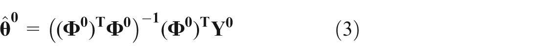
According to equation (2), the matrix vector equation is obtained

In the equation above,
and
Dynamic parameters can be obtained as follows

As for the worktable, the differential equation below is supported

where

where c = B/M and d = K/M.
Using the same identification methods, [
Followed by the parameters’ identification, four signals were used, including the current i of the motor, the rotation speed
The parameter identification for the Stribeck friction model
The frictional force modeling is necessary for accurate control of the servo system of the NC machine tool. Stribeck friction model
13
can accurately describe the characteristics of the friction at low speed and is most widely used at present. When the worktable of the machine tool moves along the guide rail at uniform speed under no-load condition, since

where
If the servo axis of the machine tool was run at uniform speed while different speeds under no-load condition, the relationship of the current i and rotational speed n of the motor can be obtained through the signal collection system. This relationship can be further converted into the correspondence relationship of the feed speed v and friction Fft. The Stribeck curve is acquired finally.
Stribeck model is described as follows 13

Fc, Fs, and σ represent Coulomb, static, and viscous friction coefficients, respectively. Vs and δ are the Stribeck velocity and the Stribeck shape factor, respectively. According to Jamaludin et al., 14 δ = 1 or 2; to simplify the calculation, δ = 1 in this article.
Let

According to the Taylor equation, the equation above can be expanded by sixth order as
Equation (7) is rewritten as

where

In case of obtaining multiple sets of


Thus, equation (6) is altered into

Using least square method,
In the model above, the viscous damping force is treated as part of the friction. However, the viscous damping force is excluded from the fictional force in the identification model above.
Thus

Identification experiment for dynamic parameters of the servo system of a large-scale CNC gear grinding machine
The identification experiment is conducted on the dressing system of the grinding wheel of a large-scale CNC gear grinding machine, as shown in Figure 3(a). The diamond dressing wheel is installed on feeding axis W, while the high-speeding grinding wheel is mounted on axis Y. The axes Y and W are independent from each other by the involute trajectory integrated through linkage interpolation. The machine employs the NUM 3050 CNC system produced by Schneider Electric. The current i and rotation speed signal ω needed in the identification for J and B are accessible through the external interfaces provided by servo drivers. Since the position loop of the NUM system can provide 1 VPP simulation signal, the position signals of encoder and grating scale (ym and y) needed in the K identification are directly available from the hardware circuit interface of the grating scale and encoder, as shown in Figure 3(b).
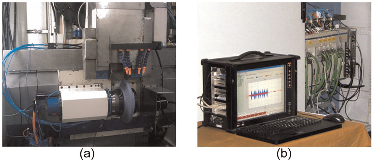
Identification testing setup: (a) the dressing servo feed system of the large-scale NC gear grinding machine and (b) data collection setup.
To ensure the feed system stimulated continuously, initial input signal of the identification for dynamic parameter beyond the friction is generated from specially designed CNC G-code. Under the driving effect of G-code, the position signal of the machine tool was exhibited as the secondary segmented curve with constant acceleration. Figure 4 displays the curves of the position, speed, and acceleration of the machine tool trajectory.

The input signals used in the identification: (a) time–accelerate curve, (b) time–velocity curve and (c) time–position curve.
The identification experiments are repeated for five times for the feed axes Y and W with input signals in the same shape while amplitudes are 1, 1.5, 2, 2.5, and 3, respectively. Figure 5(a) demonstrates a group of identification signals including the motor rotation speed w and current i of axis Y. The difference signal dy and position signal y from grating scale of axis Y are shown in Figure 5(b).
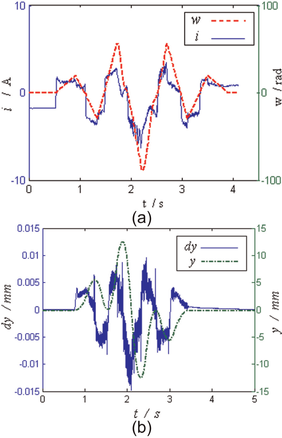
The input and output signals for the identification: (a) identification signals for inertia and damping and (b) identification signals for the stiffness.
Figure 6 shows the identification results. The identification results suggest that the equivalent rotational inertia Je and equivalent damping Be converge rapidly at the second test and present constant results. By contrast, B and K fluctuate violently as shown in Figure 7. M is directly available through the design data of the machine.

The identification results of the inertia Je and damping Be of axis Y: (a) results of Je and (b) results of Be.

The identification result on the stiffness K of axis Y: (a) results of B and (b) results of K.
The identified dynamic parameters of axes Y and W for the large-scale CNC gear grinding machine except the friction are listed in Table 1.
The dynamic parameters of the axes Y and W.

The parameter identification experiments for Stribeck model of the servo system were performed on the dressing system of the grinding wheel of a large-scale CNC gear grinding machine. With the data acquisition system, the current i in the drive motor was recorded, while jogging the axes back and forth at various speeds ranging from 0.1 to 42 rad/s. More tests were performed in the lower velocity region to better identify the boundary and partial fluid lubrication characteristics. Typical test results for the axis Y are shown in Figure 8. According to equations (6) and (8), the parameters of Stribeck fiction model are identified as shown in Table 2. By substituting the parameters obtained into equation (7), the Stribeck curve was obtained, as shown in Figure 8 with solid line. It can be seen that the curve drawn is highly consistent with the experimental data.

The forward friction test data on axis Y and the Stribeck curve obtained.
Results of the parameters’ identification for Stribeck model.

As one of the most common motions in CNC machining process, circular motion can directly reflect the dynamic characteristics of the servo system at low and high speeds. 10 Therefore, the parameter identification method is validated by comparing the simulation and experimental results of the circular motion in the dressing system for the grinding wheel of the large-scale CNC grinding machine. Control model of the servo system is small different with the model described in Figure 2 with P controller; this controller introduces the speed feedforward coefficient K forward into the position loop and a proportional–integral (PI) controller into the speed loop. The servo system simulation model of axes Y and W established corresponded to the controller. The parameters of simulation model of axis Y involve Kforward = 72%, Kppx = 8202 mm/min/mm, Kvpx = 130 mA/r/min, Tix = 20 ms, Kt = 1.1, Kbsx =7.9577 × 10⁻⁴, J = 1.34 × 10⁻³ kg m2, L = 12.8 mH, R = 1.37 Ω, M = 968 kg, Kx = 5.5 × 10⁸ N/m, and B = 27,742 N s/m. The friction model uses the Stribeck model. The parameters in Table 2 are transformed into the values of worktable, namely, Fs = 1.8690 × 10³ N, Fc = 1.2666 × 10³ N, and Vs = 2.9080 × 10⁻³ m/s.
The simulation conditions are as follows: F = 2 m/min and the radius R of the circular motion is 25 mm. The simulation results are displayed as the dotted line in Figure 9.The experimental conditions of the machine tool are consistent with the simulation conditions. The NC controller parameters are identical with the controller parameters of the simulation model. The test results are shown as the solid line in this figure.

Comparison of experimental results and simulation results of the circular motion of servo system.
The results of the simulation and experiment are shown in the figure. To ensure that the results are displayed normally in the polar co-ordinate, all the values displayed in Figure 9 are adjusted by adding a constant (here 2 × 10⁻⁵) to the contour errors. The curves by the simulation and the experiments show their similar profiles and behaviors at different places especially at four quadrants of the circular motion. As shown in the figure, there appears to be a good correspondence between the two sets of the results for the protrusions on the horizontal axis. Although the correspondence is not good enough for the protrusions on the vertical axis, the test results suggested that the errors between the curves by the simulation and experiment are no more than 3 μm, and dynamic behaviors shown by the simulation and experiment curves including emerge time, lasting-time, and the maximum value of height of the protrusions are in good consistency. This outcome proves that the dynamic characteristics of the simulation system constructed are consistent with those of the real system. Meanwhile, the dynamic parameters used in the simulation are basically consistent with those in real system. However, there are differences between the values of simulation and identification parameters.
To index the performance of the presented methods, relative error between identification and simulation parameters is obtained as in Table 3.
Relative error for identification parameters to simulation for Y axis.
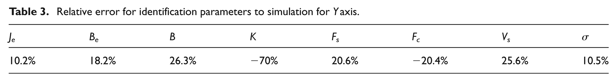
From the table, all relative errors are no more than 27% except K. The evident differences are attributed to the stiffness difference among the joint faces of the worktable. Especially, when the joint faces move downward at different speeds, the contact stiffness presents large variations. 15 Even though the identification result can also provide references for the evaluation on the overall stiffness of the worktable. They are applicable to evaluate the variations in the overall mechanical stiffness of the machine tool in different working environments or different life phases of a machine tool and thus to realize the rapid performance evaluation and fault diagnosis of the servo system of the CNC machine tools.
Conclusion
This article presented an identification method for the dynamic parameters of the servo system using the internal signals of the CNC system. The identification model for the dynamic parameters of the servo system was first established. By solving this model using the least square method, the dynamic parameters including equivalent inertia, equivalent damping, worktable damping, and the overall stiffness of the mechanical system were available. Using the experimental method, the friction curve of the servo system of the NC machine tool was obtained. By high-order Taylor expansion on the Stribeck curve, the nonlinear model was linearized, and the five parameters of the Stribeck friction model were solved using the least square fitting method. Using the dynamic parameters obtained, the simulation model for the servo system of the large-scale CNC gear grinding machine was established. To verify the validity of the method, identification experiment was conducted to verify the effectiveness of identification method. The stable experiment results suggested that inertia and damping identification experiment converged fast. Stiffness identification experiments showed some error under the influences of nonlinear error and stiffness. However, the identification results were still of reference significance. Using the identification parameters, the circular motion of the CNC gear grinding machine system was simulated using the model and tested by the experiments; the results of comparison suggested that the identification method proposed in this article is valid.
Footnotes
Academic Editor: Yaguo Lei
Declaration of conflicting interests
The author(s) declared no potential conflicts of interest with respect to the research, authorship, and/or publication of this article.
Funding
This project was supported by the Natural Science Foundation of Shanghai of China (Grant No. 13ZR1427500), the Key Projects in the National Science & Technology Pillar Program of China (Grant No. 2012BAF01B02), and the National Natural Science Foundation of China (Grant No. 51005158).