
Abstract
Currently, due to the rare consideration on the coupling of the various rolling joints and their directional dynamic parameters, and the constraints of the traditional modeling methods, the dynamic modeling precision of the ball screw feed system and the dynamic parameters identification accuracy of the rolling joints are difficult to be further improved. In this paper, a novel method to identify the dynamic parameters of rolling joints based on the digital twin dynamic model of the assembled ball screw feed system is proposed. Firstly, synchronizing information of the physical entity, the geometric model is constructed. Then the finite element analysis (FEA) model is constructed which can simultaneously consider multiple rolling joints and their dynamic parameters at multiple directions. Based on the FEA modal data, the deep neural network (DNN) model is constructed to reflect the mapping between the dynamic parameters and the natural frequencies. Thus, the digital twin dynamic model can be established by fusion of these sub-models. Combining the digital twin-driven and experimental natural frequencies, the optimization model is built, and the dynamic parameters can be identified by particle swarm optimization (PSO) algorithm. Finally, the relative error of dynamic parameters identification is less than 3%, which indicates that the proposed method is feasible, effective, and has greater accuracy.
Keywords
Introduction
Ball screw feed system has been widely used in computer numerical control (CNC) machine tools as the good positioning accuracy, high transmission efficiency, strong reliability, and relatively low cost. 1 The system is composed of the lead screw, nut, rolling guides, bearings, working platform, bed, and other parts connected by different kinds of joints. 2 As the movable joints, the rolling joints are not only numerous but also widely distributed, whose stiffness is smaller than that of the fixed joints, significantly affecting the dynamic performance of the system. 3 Therefore, it is of great importance to accurately establish the dynamic model of the ball screw feed system and identify the dynamic parameters of the rolling joints for evaluating the dynamic performance and improving the designing level of a machine tool.
For dynamic parameters identification of joints for machine tools, researchers have mainly adopted theoretical calculation method, experimental method, and the method combining theory with experiment. 4 At present, studies on dynamic parameters identification of rolling joints in the ball screw feed system are basically conducted by these three methods. No matter which method is adopted, it is commonly assumed that different directional dynamics are completely decoupled when modeling, 5 and then independently identifying the dynamic parameters in one direction. Due to the large ratio of length to diameter of the lead screw, the vibration of each cross section is quite different along the axial direction, 6 leading to the complex axial dynamic performance of the feed system. Therefore, many scholars have focused on axial dynamic parameters of rolling joints. Jiang and Zhu 7 calculated the linear stiffness of linear rolling guideway, the axial stiffness of the ball screw pair and the angular contact ball bearing based on the Hertz Contact Theory. Hu et al. 8 established the axial stiffness identification models of the lead screw at the supported point and the nut position based on initial parameter method, and then solved the axial stiffness by substituting experimental data into the built analytical equations. Hu et al. 9 established the axial stiffness model of the ball screw mechanism according to the theory of Hertz Contact Theory, considering the coupling relationship between the pressure of the rolling guide and the contact angel. Zhu et al. 10 simplified the lead screw as an elastic rod to establish the axial vibration equations of the lead screw and the working platform with a harmonic excitation force exerted, and constructed the axial dynamic parameters identification model of the rolling joints in an assembled ball screw feed system. Combining the theoretical analytical equations with the experimental results, they identified each stiffness and damping parameter by Genetic Algorithm. In addition, because the lead screw is a slender rod, the radial stiffness of the feed system is smaller than the axial stiffness, and vibration with large amplitude is more likely to occur in radial direction, reducing the machining accuracy. 11 Therefore, accurately identifying the radial dynamic parameters of rolling joints in the ball screw feed system is also of great significance to improve the machining accuracy. Hu et al. 12 deduced the stiffness identification model of bearing joint by the synthetic substructure method on the basis of theoretical analysis and experiments, and then identified the radial stiffness through measuring the frequency response functions (FRFs) of the lead screw in different positions as well as the whole structure. Dhupia et al. 13 established parametric model of the dynamic parameters of the linear guide in the supported direction of the feed system based on Hertz Contact Theory and 2-dimensional Chebyshev polynomials. Okwudire 14 proposed a screw-nut interface stiffness model which incorporated the elastic deformation of the screw within the nut by Timoshenko beam shape functions. Zhu et al. 15 simplified the screw as an Euler-Bernoulli beam to build the radial vibration equations at different sections. Combining the experimental radial displacements, they established the optimization goal function and then identified radial stiffness and damping of each rolling joint by artificial fish swarm algorithm (AFSA).
The mechanical structure of the ball screw feed system is very complex, and all directional dynamics have a non-unneglectable coupling effect. Moreover, different rolling joints and their different directional dynamic parameters work together to affect the dynamic performance of the system.1,5 Therefore, dynamic parameters in different directions should be considered at the same time when modeling. Dadalau et al. 16 calculated the axial and torsional stiffness of the ball screw spindle according to parametric equations. Then Frey et al. 17 regarded the stiffness in different directions as parameters related to the equivalent diameter, and established the dynamic model of the ball screw feed system to solve the first two order natural frequencies. Rui et al. 18 adopted multiple axial and radial spring-damping elements to characterize the contact features of rolling joints, and constructed the equivalent parametric identification model of the bearing assembly based on the resonance method. Combining the built analytical model with the experimental results, they solved the axial and radial stiffness and damping parameters. Li et al. 19 obtained the amplitude-frequency curves in the horizontal and vertical directions, and then calculated the contact stiffness of the rolling guide joint in the two directions by the method of single degree of freedom (DOF) components. Fu et al. 20 respectively deduced the normal and tangential stiffness of each rolling joint of the feed system by Hertz Contact Theory, and substituted the solved results into the FEA model to acquire the first five order vibration modes and natural frequencies. The final maximum error between the simulated natural frequency and the experimental data is 8.9%. Dynamic parameters of one single joint are assigned or identified in the above literatures, achieving high accuracy of dynamic modeling or parameters identification. However, due to the complex mechanical structure mentioned above, the dynamic performance of the ball screw feed system is affected by various rolling joints and their dynamic parameters in different directions, the dynamic model of the system presents the characteristics with multi-inputs and multi-outputs, high nonlinearity and strong coupling. Establishing the accurate equivalent dynamic model is the prerequisite for effectively identifying the dynamic parameters of joints. At present, the mainstream analytical method still inevitably needs some simplification, which is difficult to meet requirement of simultaneously considering the multiple rolling joints of the ball screw feed system and their multiple directional dynamic parameters, so as to restrict the dynamic modeling precision. And for the common finite element method, the isolate FEA model is difficult to directly reflect the dynamics of the ball screw feed system as the initial value of the stiffness and damping can’t be foreknown in advance. Therefore, it is very necessary to establish an equivalent dynamic model that can simultaneously consider the multiple rolling joints and their various directional dynamic parameters, and accurately reflect the mapping relationship between the dynamic parameters of rolling joints and dynamic performance of the system.
With the integration of the new information technologies such as big data, cloud computing, Internet of things, and artificial intelligence with manufacturing industry, the physical world of manufacturing and the informative world can be further interconnected, so as to promote the realization of intelligent manufacturing.21,22 As a novel intelligent and interdisciplinary technology, digital twin establishes the virtual models of physical entities through digital means, and simulates the behavior of physical entities in reality via data. It extends new solutions for practical problems by some technical steps such as the virtual and real interactive feedback, integrative analysis of data, and iterative optimization of decision. 23 Currently, digital twin has been already applied in manufacturing, production management and optimization design, and made some good effects to a certain extent. According to the concept of digital twin, Siemens established the production system model integrating manufacturing processes to support the digital transformation of the enterprises. 23 NASA researched the fault prediction and elimination methods of complex systems based on digital twin by combining the physical models with the virtual models. 24 Tao and Zhang 25 explored a novel concept of digital twin shop-floor (DTS) and elaborated its four key components: physical shop-floor, virtual shop-floor, service system of the shop-floor, and the digital twin data of the shop-floor. Their studies provided basic theoretical support for the application of digital twin in manufacturing. Cai et al. 26 deployed sensors to capture the machine-specific features signals, and conducted data fusion analysis for modeling and developing the digital twin virtual machine tool. Zhang et al. 27 proposed a material parameters optimization method based on digital twin and radial basis functions (RBF) model to improve vibration issues caused by clearance of root-joints during deployment of the spacecraft hatch. Based on the current studies, digital twin has provided new solutions to various problems about complex systems.
Benefiting from the continuous development of modeling and simulation technologies, as well as the rapid improvement of computational power for computers, the difficulty and cost of automatically obtaining a large number of sample data are reduced greatly. On the premise that big data can be obtained, more accurate digital twin models are established through data-driven and information interaction, thus the simulation, prediction, evaluation, and optimization can be conducted on physical entities effectively. Although digital twin is rare applied in dynamic modeling and dynamic parameters identification of joints in machine tools, it can be inferred that it has the potential to solve such problems.
In this paper, a new approach to dynamic parameters identification of rolling joints based on the digital twin dynamic model of the self-designed ball screw feed system is proposed. Firstly, the dynamic characteristics of rolling joints are equivalent to a series of elastic joints which can consider the stiffness and damping in different directions at the same time, so as to establish the multibody dynamics FEA model of the assembled ball screw feed system. Secondly, on the basis of obtaining a large amount of FEA modal data, DNN is utilized to build the mapping relationship between the dynamic parameters of rolling joints and the natural frequencies of the feed system, so as to realize the digital image of the FEA model. Thus, the digital twin dynamic model of the ball screw feed system is established to mirror its dynamics. Thirdly, the optimization identification model of dynamic parameters is established through combining the predicted natural frequencies by the digital twin dynamic model and the experimental values measured by the modal test. Lastly, the different directional stiffness and damping parameters of different rolling joints are identified simultaneously by PSO algorithm, and higher identification precision is achieved than previous studies.
Concretely, the rest of this paper is organized as follows: Section 2 presents the basic architecture of the proposed method. The digital twin dynamic model of the ball screw feed system is established in Section 3. Experimental modal test is conducted on the ball screw feed system in Section 4; Section 5 expounds works about the optimization identification of dynamic parameters and discusses the results. Finally, Section 6 concludes the paper and comes up with some future possible work.
The architecture of the proposed methodology
Digital twin is the virtual model established by digital means in virtual space which can faithfully reflect part of even the whole lifecycle-oriented performance of the entities in physical space with high fidelity and credibility.23,24,27–29 Establishing a digital twin model is a simulation process integrating multi-physical quantities, multi-scale, and multi-probabilities, and it integrates the geometric, physical, behavior, and some other properties of the entities by information interaction. In this paper, the approach to dynamic parameters identification of rolling joints based on the digital twin dynamic model of the ball screw feed is proposed, whose architecture is shown in Figure 1, mainly including the information interaction and mapping in physical, virtual, and application space.

The architecture of the proposed method in this paper.
Physical space
For works in this paper, the physical space refers to the physical entity of the ball screw feed system, including geometric property such as mechanical structure and dimensions, physical property such as materials, kinematic pairs, joints, and experimental modal tests conducted on the physical entity by sensors and test equipment to obtain experimental information, such as natural frequencies and modal shapes.
Virtual space
Synchronizing information of the physical entity, the geometric model of the ball screw feed system is built by 3-dimesional mechanical modeling software. With the geometric model as the carrier, dynamics of different rolling joints are equivalent to a series of elastic joints in FEA software those can consider different directional stiffness and damping parameters at the same time, thus the multibody dynamics FEA model of the ball screw feed system is established. A large number of random, uniform and disordered dynamic parameter samples of the rolling joints are generated within a reasonable range, and then they are substituted in sequence to the FEA model for modal analysis, so as to obtain a large number of FEA calculated natural frequencies under the conditions of corresponding stiffness and damping parameters. The DNN model of the ball screw feed system dynamics is constructed by taking various directional stiffness and damping parameters of different rolling joints as the inputs, and the FEA calculated first six order natural frequencies of this system as the outputs. Moreover, the generated stiffness and damping samples as well as the corresponding FEA results are adopted as the datasets to train the DNN model. The mapping relationship between the dynamic parameters of rolling joints and the first six order natural frequencies of the ball screw feed system can be built via the fully trained DNN model, so as to realize the digital image of the FEA model. Consequently, the digital twin dynamic model of the assembled ball screw feed system in this paper can be established to obtain the digital twin-driven natural frequencies.
Application space
For the research purpose of this paper, the dynamic parameters of rolling joints in the assembled ball screw feed system can be identified with the help of the experimental information tested in physical space and the digital twin modal data obtained in virtual space. Specifically, all the stiffness and damping parameters to be identified are taken as the design variables, and value ranges for dynamic parameters in different directions of different rolling joints are taken as the constraint conditions. The objective function is set up by combining the experimental natural frequencies with the predicted values by the digital twin model. Finally, all the stiffness and damping parameters can be identified simultaneously by PSO algorithm.
The digital twin dynamic model of the ball screw feed system
A digital twin model is the multi-dimensional, multi-scaled, and multi-domainal description of the physical entity, oriented to the demand. It is the faithful digital replica of the physical entity.28–32 Some researchers have proposed a complete theoretical system of the digital twin model establishment, including model construction, model assembly, model fusion, model verification, model validation, and model management. However, not all of them are needed in actual studies, and they ought to be accordingly selected combining with practice. 32 In this paper, establishing the digital twin dynamic model of the ball screw feed system mainly includes model construction, model fusion, and model verification, and the process is shown in Figure 2.

Process of establishing the digital twin dynamic model of the ball screw feed system.
The basic structure
Taking the self-designed ball screw feed system as the research object, its digital twin dynamic model is established in this paper. The structure of this feed system is shown in Figure 3. The servo motor drives the lead screw to rotate via the coupling, and then the linear motion of the working platform is converted by the nut. The lead screw at the end near the motor is fixedly supported by a pair of angular contact bearings, and the other end is simply supported by a single angular contact bearing. For the ball screw feed system, there are two main kinds of joints, namely, the fixed joint connected by bolts and the rolling joint forming various kinematic pairs by rolling elements. The fixed joints can be regarded as rigid connections owing to their large stiffness and damping. 10 The rolling joints include the lead screw-nut joint, the bearing joint at fixed end, the bearing joint at simply supported end, and the rolling guide joint. Generally, when a machine tool is processing, the working platform is mostly located in the middle of the stroke. In this paper, in order not to lose generality, the nut is adjusted to the middle of the lead screw, and the working platform is set to the middle of the bearings at both ends, so as to conduct the dynamic studies in this paper.

Basic structure diagram of the ball screw feed system. 1 – servo motor, 2 – coupling, 3 – bearing carrier, 4 – bearing at fixed end, 5 – lead screw, 6 – slider, 7 – nut, 8 – nut holder, 9 – working platform, 10 – guide, 11 – bed, 12 – bearing carrier, 13 – bearing at supported end.
The FEA model
Synchronizing physical information of mechanical structure, geometric dimensions, fitting status and other properties, the 3-dimensional geometric model of the assembled ball screw feed system is built by SolidWorks. Then this geometric model is imported into the multibody dynamics-module of COMSOL Multiphysics, and the contact characteristics of different rolling joints are equivalent to a series of matching elastic joints predefined in the software. Additionally, the total stiffness and the total damping in x, y, z directions are respectively defined in the stiffness matrix and damping matrix of each selected elastic joint. According to the contact area of the specific joint and the generated mesh elements, the stiffness and damping parameters are automatically equally distributed. Thereby, the FEA model of the ball screw feed system is established to conduct modal analysis. The key steps are described as following:
Basic pretreatments
Definition for material
Based on the actual conditions, the material properties of the FEA model are set as shown in Table 1.
The material properties of parts for the ball screw feed system.

Setting constraints
As for the physical entity of the assembled ball screw feed system, the bed is fixed on the base, and the base is fastened to foundations through anchor bolts. Based on the entitative information in physical space, the fixed constraint is applied on the bottom of the bed in the FEA model.
Meshing
The feed system FEA model is meshed by the combination sweep. Namely, the quadrilateral element is adopted to fine mesh the parts those are sensitive to vibration such as lead screw and nut. And the triangular element is utilized to mesh the irregular parts such as the working platform and carriers. There are about 48,500 units in total for the FEA model.
Modeling of the rolling joints
The ball screw feed system is a typical complex multi-body system, which is composed of multiple parts connected by different joints. The topologies, constraints, and kinematic pairs among the components are quite different, leading to various contact characteristics of joints. In general, the mechanical joint performs both with elasticity and damping because there exists micro unevenness and gaps between the contact parts and relative motion may occur during vibration. At present, the spring-damping node element is mostly adopted to characterize the contact features.4,33 Because of this modeling method, the joint whose contact surface is plane, such as fixed joint and sliding joint can be characterized well.34,35 However, as the non-planar contact surface, 36 it is very difficult for rolling joint to determine the position and number of the spring-damping element nodes, thus the dynamic modeling precision is restricted. The accurate FEA model is the important basis for establishing the digital twin dynamic model of the ball screw feed system. In this paper, the contact characteristics of different rolling joints are equivalent to a series of predefined elastic joints in the multibody dynamics module of COMSOL Multiphysics, whose total stiffness and total damping in every direction under the Cartesian coordinate system are respectively defined. The specific settings are shown in Figure 4.

Rolling joints are equivalent to a series of flexible joints.
Set the transmission direction of the ball screw feed system as the x-direction, the supported direction as the y-direction, the direction both perpendicular to x and y as the z-direction. The lead screw-nut joint is composed of a lead screw, balls, and a nut. The balls transmit load and motion between the lead screw and nut to form the lead screw-nut pair, by which the rotary motion is converted to the linear motion. For the lead screw-nut joint, it is of translational DOF and rotational DOF in the x-direction, and they are linearly related. According to the predefined properties for DOF of each elastic joint in multibody dynamics module of COMSOL Multiphysics, as shown in Table 2, the screw joint is selected to characterize the lead screw-nut joint, and different directional dynamic parameters are respectively defined as
The predefined DOF of each joint in multibody module of COMSOL Multiphysics.
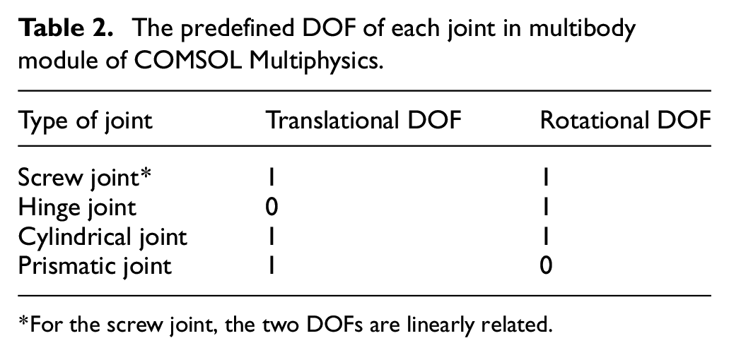
For the screw joint, the two DOFs are linearly related.
Through the above setting, the FEA model of the assembled ball screw feed system is built as shown in Figure 5, by which different directional dynamic parameters of multiple rolling joints can be simultaneously considered to conduct FEA modal analysis.

The FEA model of the ball screw feed system.
The FEA modal analysis
Through the parametric scanning function of COMSOL Multiphysics, input parameters can be automatically extracted set by set, and then substituted into the FEA model in sequence to obtain the calculation results under corresponding conditions. Thus, a large amount of required sample data can be generated which is helpful to establish the accurate digital twin model.
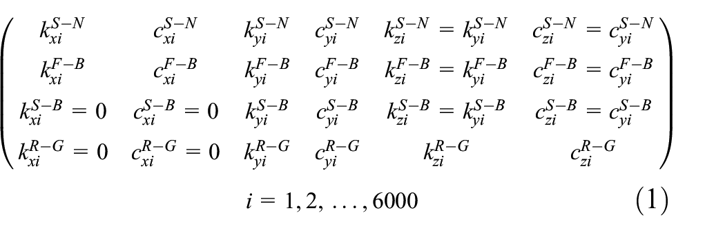
In order to obtain the sample data, it is necessary to determine the ranges of different directional stiffness and damping parameters of different rolling joints firstly. According to Hertz Contact Theory and literature survey,4,37,38 the ranges of all the dynamic parameters are listed in Table 3. In this paper, among the determined value ranges, 6000 sets of dynamic parameter samples are randomly, uniformly, and disorderly generated as shown in equation (1). These dynamic parameters of rolling joints are taken as the inputs, and they are extracted in sequence for FEA modal analysis. So, corresponding 6000 sets of the first six order natural frequencies of the feed system can be obtained, which are set as the output samples. Therefore, the datasets of the digital twin dynamic model of the ball screw feed system have been generated for the DNN model designing and training next.

Ranges of different directional dynamic parameters of each joint.

The DNN model of the ball screw feed system
With the development of computational ability for computers, the FEA simulation technology has been widely applied in various fields, and also plays a very important role in equivalent dynamic modeling of machine tool joints. With the help of FEA simulation software, the contact characteristics of the joints can be simulated conveniently, and then the dynamics can be analyzed. However, as the closure of the joints and the complexity of influence factors, it is generally difficult to accurately foreknow the equivalent dynamic parameters of the joint, so that the isolated FEA model can hardly positively reflect the nonlinear relationship between the dynamic parameters and the modal results of the joints, thus it is difficult to be used to the dynamic issues of mechanical systems considering the joints. Therefore, the FEA model is hardly taken as the equivalent dynamic model of the joint directly.
Because DNN has strong nonlinear data mapping ability, it can be used as a modeling method for complex data. In this paper, the DNN model is constructed by taking the dynamic parameters of rolling joints as the inputs, and the first six order natural frequencies of the feed system as the outputs. Then the DNN model is trained with dynamic parameter samples and the FEA solved natural frequencies under the corresponding conditions as the datasets, so as to realize the digital image of the traditional FEA model which can reflect the complex mapping between the dynamic parameters and modal results. The accuracy of the trained DNN model directly affects the validity of the digital twin dynamic model. Finally, the digital twin dynamic model of the assembled ball screw feed system is established.
The DNN model designing
According to the modeling principle shown as the virtual space part in Figure 1, in this paper, the mapping relationship between the stiffness, damping parameters of rolling joints, and the first six order natural frequencies of the system is reflected by the error back propagation (BP) neural network model with multiple hidden layers (deep neural network, DNN). Figure 6 shows the diagram of a typical DNN model with (h + 2) layers. The first is the input layer to receive input signals without operating, including m inputs

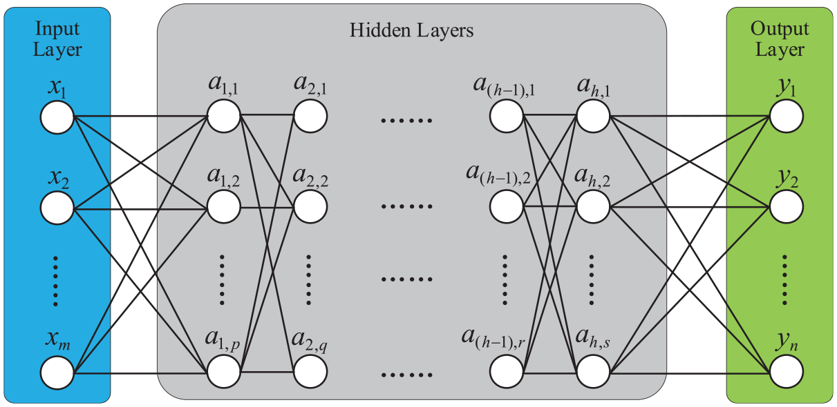
Basic structure of a typical DNN model.
Each neuron in the hidden layer and the output layer represents a specific output function, which is called excitation function f; Every two neurons in the adjacent layers are connected through a certain weight w to transfer signals, meanwhile the deviation b should be considered.
41
Therefore, the output vector

Where,
As mentioned above, BP is adopted for network propagation. Firstly, the weight and deviation are initialized, and then the error is calculated via a loss function, which will be backpropagated from the output layer to the hidden layers, until to every neuron.39,41 Each neuron is driven to search the minimum of the loss function through gradient descent algorithm, so as to determine the optimal weight and deviation. Finally, the value of loss function may reduce to optimize the DNN model. Learning rate is adopted to control the search rate during this process. In this paper, the learning rate and the minimum gradient are respectively set to 0.01 and

The DNN model training
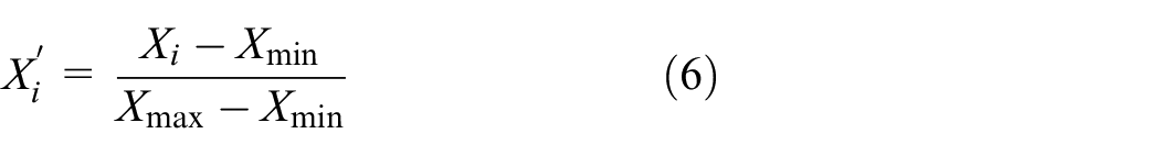
The above obtained 6000 sets of dynamic parameters of rolling joints and the first six order natural frequencies of the ball screw feed system solved under the corresponding conditions are taken as the training datasets. Due to the large ranges of the input samples, the singular samples will be generated during training, which may increase the training time or failure to converge. Original input parameters are all normalized and converted within [0,1] by equation (6), where,
According to the data generation method described in Section 3.2.3, another 500 sets of non-training sample data are taken as the test datasets. The mean absolute error (MAE) and the mean absolute percentage error (MAPE) of the test datasets are calculated by the trained DNN models with 2–10 hidden layers. The dimensional MAE and the dimensionless MAPE are adopted as the evaluation indicators to reflect the proximity between the predicted natural frequencies
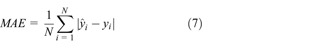

Similarly, N represents the number of samples. The smaller the value of the two evaluation indicators, the predicted natural frequencies

The performance comparison of DNN models with different hidden layers.

The loss curves of the trained DNN model with 6 hidden layers.
The natural frequencies of the test datasets are analyzed gradually by order through the trained DNN model with 6 hidden layers, thus MAE and MAPE of each order natural frequency can be obtained. As shown in Table 4, it can be seen that MAE of each order natural frequency is less than
Prediction precision of each order natural frequency for the testing datasets.

The digital twin dynamic model of the assembled ball screw feed system is established based on fusion of the above mechanical model, the FEA model and the DNN model, by which, the dynamic performance of the system in physical space can be mirrored in virtual space.
Experimental modal test
Theoretically, machinery dynamics is studies on the response of mechanical systems under load excitation. Depending on the dynamic characteristics of the structure, the external load will lead to the response of the mechanical system at different frequencies. Generally, the dynamic characteristics of the mechanical structure refers to the frequency, damping, and modal shapes, 4 which are independent to the external excitation and the system response, and can be obtained through modal analysis. Essentially, modal analysis mainly studies the natural characteristics of the structure, especially the natural frequencies and the modal shapes. Mastering these modal parameters is greatly helpful to dynamic modeling and the optimal designing. Experimental modal test is a classical method of modal analysis. The structure is excited through the excitation device, and the vibration data is collected with the help of sensors and data acquisition equipment. Finally, the modal results can be extracted.42–44
In this paper, this classical method is followed to carry out the experiment. The self-designed ball screw feed system is taken as the research object, whose nut is adjusted to the middle of the lead screw, and the working platform is set to the middle of the bearings at both ends. In order to obtain the experimental modal results of the physical entity, the LMS test. Lab (LMS for short) is adopted to conduct on the feed system at this condition. The whole LMS is mainly composed of the excitation device, front-end sensors, the data acquisition device, and modal analysis software installed in the computer. Based on the principle shown in Figure 9, the impact hammer is used as the excitation device to hammer the excitation point, and a force sensor is installed in the hammer head, and an accelerometer is placed at the measuring points in turn to pick up the vibration signals. Then the signals are transmitted to the data acquisition device, and the test data is processed and analyzed through the modal analysis software to obtain the experimental modal results.
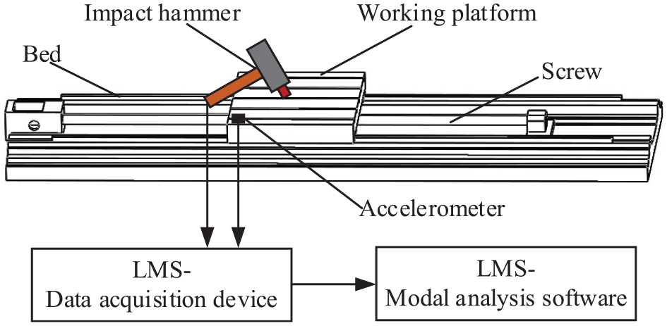
Basic principle of experimental modal test.
Based on the above principle of the experimental modal test, the hammer test is carried out through the way that excitation at single point and response at multiple points. The experimental site is shown in Figure 10. Firstly, the equivalent 3-dimensional model as shown in Figure 11 is built in LMS modal analysis software, and 33 measuring points are arranged on its surface, each of which corresponds to the actual position of the entity one by one. In this work, the center position on the upper surface of the working platform corresponding to the No. 33 measuring point is set as the excitation point. For reasonable sampling, the sampling bandwidth is set to 1024 Hz. Then the Kistler9724A200 impact hammer is utilized to knock at this position to excite the structure, and a BK4525B 3-directional accelerometer arranged at the corresponding measuring point is adopted to pick up the vibration signals at this position in x, y, z directions. After completing acquisition of this measuring point, move the 3-directional accelerometer to pick up the vibration signals at the next point, so as to gradually complete the test of all 33 measuring points. In particular, during the experiment, the excitation point is effectively hammered for five times when collecting signals for each measuring point, thus reducing the human errors by taking the average. All vibration signals are transmitted to the LMS data device, and the test data is processed and analyzed through the LMS modal analysis software to obtain the experimental results of the first six order natural frequencies and modal shapes, as shown in Table 5 and Figure 12 respectively.

The experimental site.

Equivalent model and arrangement of measuring points of the experimental modal test.
Experimental results of the first six order natural frequencies.


Experimental modal shapes: (a) first order (b) second order (c) third order (d) fourth order (e) fifth order, and (f) sixth order.
Optimization identification of dynamic parameters
Through information transmission, the relevant data gathered in physical space and the relevant information obtained in virtual space are both transmitted to the application space. Aiming at the specific demand for dynamic parameters identification of the rolling joints in the ball screw feed system, the optimization identification model is built by combining the experimental modal test results with the predicted natural frequencies by the digital twin dynamic model, and the PSO algorithm is adopted to identify all the stiffness and damping parameters at the same time.
The optimization model
Based on the study architecture as shown in Figure 1, it is necessary to build the optimization model for identifying the dynamic parameters of rolling joints in the ball screw feed system. In this paper, the 14 stiffness, damping parameters to be identified are taken as the design variables, denoted by

Where, since each damping to be identified in Table 3 is within
Optimization identification
Since it is very difficult to express the relationship between the variables and the objective function of the optimization model with certain formulas in this paper, optimization algorithms are mostly adopted to solve such “black box” problems.45,46 PSO algorithm is widely applied as its simple algorithm, fast convergence, strong robustness, and suitability for real number-issues.47–49 Therefore, it is utilized in this paper to identify the dynamic parameters of rolling joints in the ball screw feed system.
Through PSO algorithm, the optimization issue is regarded as that to search for the positions of the bird swarm in a certain space, and each bird is regarded as a none-mass and none-volume particle with speed and position, which are determined by equations (10) and (11) respectively.
47
The particle quality is evaluated by the fitness


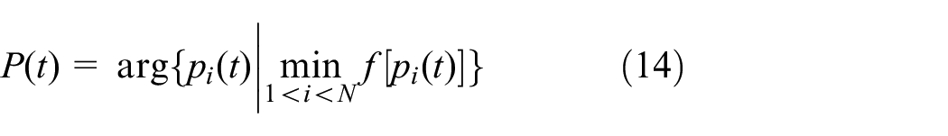
For PSO algorithm, the number of birds in the swarm is called population N, which is the number of optimization variables in equation (7), that is

In equation (9),
The historical best position of the ith particle at the tth moment is denoted as

The global best positions of particle swarm
According to the basic principle of PSO algorithm, the process of solving the optimization problem in this paper is shown in Figure 13, through which all the stiffness and damping parameters of rolling joints can be identified simultaneously.
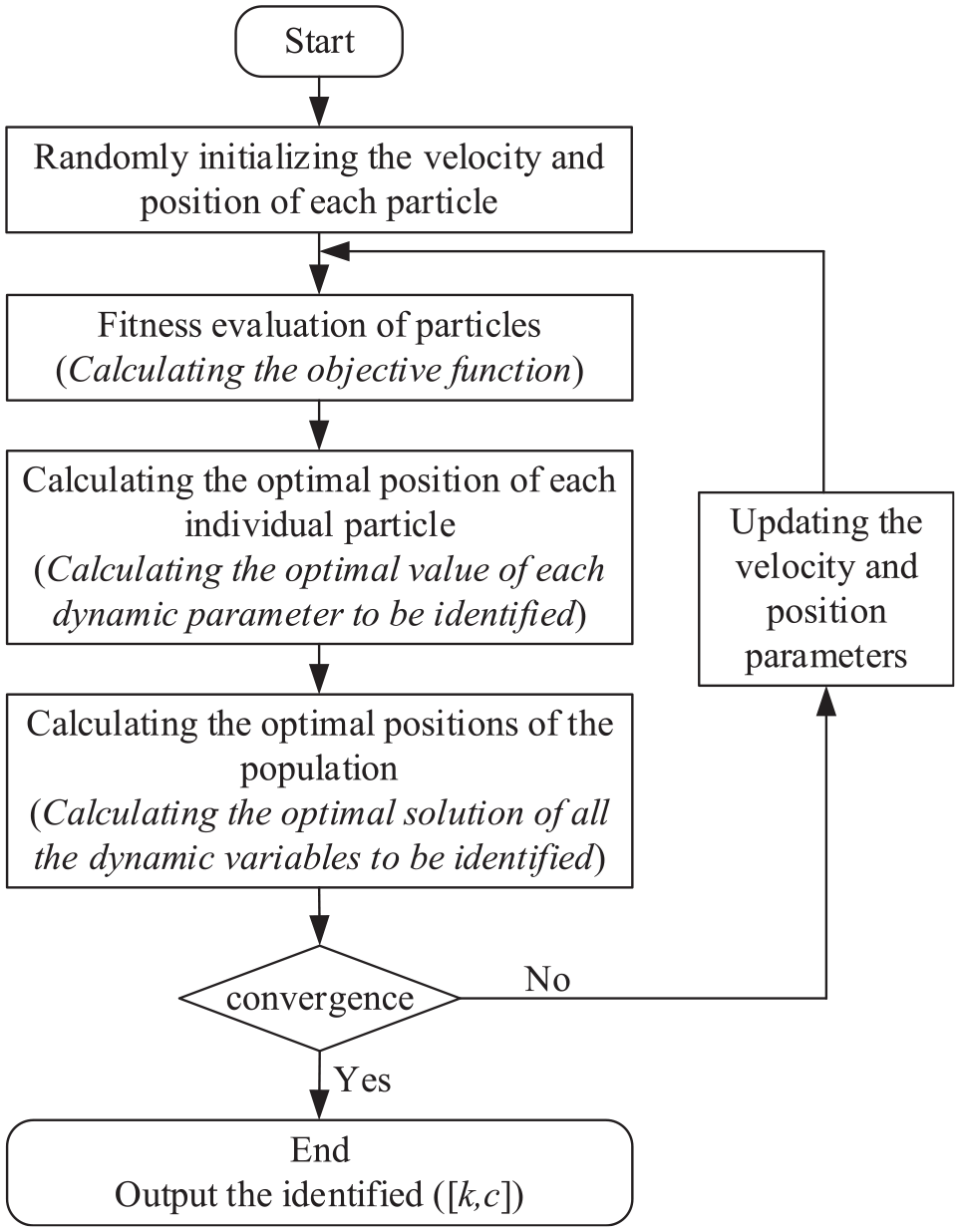
The process of optimization identification.
In this paper, the cut-off condition of optimization is set as that the maximum number of iterations reaches to 500 or the value of the objective function is less than 0.10. The loss curve of the optimization identification process is shown in Figure 14, which is convergent and shows the effectiveness of the optimization. Moreover, all the identified dynamic parameters of different rolling joints in different directions is listed as shown in Table 6.

The convergence curve of the optimization identification.
Results of optimization identification.

Model verification
Taking the above identified results in the application space into the digital twin model in virtual space to conduct the FEA modal analysis, then the first six order modal shapes and natural frequencies can be obtained. The solved modal shapes are shown in Figure 15, which are consistent with the experimental results by the modal test as shown in Figure 12. The solved natural frequencies and the comparison with the experimental values are listed in Table 7. It can be seen that the absolute relative errors (ARE) between the FEA calculated natural frequencies and the experimental results are all less than 3%, reaching great identification precision, thereby demonstrating the effectiveness of the proposed modeling method.

The FEA modal shapes by the identified dynamic parameters based on the proposed method: (a) first order (b) second order (c) third order (d) fourth order (e) fifth order, and (f) sixth order.
The identification accuracy of this paper.

In addition, in order to further verify that the proposed method is more accurate in dynamic modeling and has greater dynamic parameters identification precision of joints, the ARE of each order natural frequency is taken as the evaluation indicator, compared with the results by methods which only consider the single directional dynamic modeling, as well as have achieved high accuracy in other published literatures. The final comprehensive comparisons are shown in Table 8.
Comprehensive comparison with other methods (ARE, %).

It can be clearly seen that only considering axial or radial dynamic parameters will lead to some abnormal errors, which demonstrates that the coupling of various directional dynamic parameters of multiple joints ought to be considered simultaneously, and further indicates that the established digital twin model should be faithful to the physical entity. Moreover, the AREs of the first five order natural frequencies solved by the proposed method are all far less than the results in Zhu et al. 2 and Zheng, 11 merely the sixth order ARE is slightly higher. However, since the sixth ARE is 2.9%, which is already rather small, furthermore, the low-order dynamics are more concerned, the comparison for this order can be ignored. Additionally, the average ARE of the first six order natural frequencies calculated by the proposed method is obviously less than those solved by others. Generally, the dynamic parameters identification accuracy based on the proposed method is better than those in the two literatures mentioned above, which shows the accurateness and advantages. In conclusion, the proposed method is of greater dynamic modeling precision and can identify the dynamic parameters of rolling joints in the ball screw feed system more accurately.
Conclusion and future work
This paper presents a novel method to simultaneously and accurately identify the dynamic parameters of the rolling joints in an assembled ball screw feed system based on the digital twin dynamic model of the system. Firstly, with sufficient consideration of various directional dynamic parameters of multiple rolling joints and their coupling, a series of elastic joints whose stiffness and damping parameters in different directions needed to be simultaneously defined have been adopted to characterize the different rolling joints. Then, benefiting from the FEA-generated big data of multibody dynamics modal analysis, the mapping relationship between the stiffness, damping parameters of rolling joints and the first six order natural frequencies of the system is built through DNN, so as to complete establishing the digital twin dynamic model of the ball screw feed system. Next, the optimization model of dynamic parameters identification is constructed through combining the experimental results measured by the modal test with the predicted data driven by the digital twin model. And PSO algorithm is used to solve the optimization problem, thus to identify all the stiffness and damping parameters of rolling joints. Finally, through a series of comprehensive comparisons, it is verified that the maximum ARE between the FEA calculated natural frequencies based on the identified dynamic parameters and the experimental values is less than 3%, which achieves greater identification accuracy than other modeling methods and indicates the superiority of the proposed method in this paper.
The main contribution of this paper is that a novel method to identify the dynamic parameters of rolling joints based on the digital twin dynamic model of the ball screw feed system is proposed. By mirroring the attribute information of the physical entity of the ball screw feed system, the 3-dimensional geometric model, the FEA model, and the DNN model are successively constructed, and finally the digital twin dynamic model of the system is established by fusion of these sub-models which realizes the consideration of the multiple rolling joints and their various directional dynamic parameters at the same time, improving the dynamic modeling precision significantly. Moreover, combining the digital twin-driven natural frequencies with the experimental results, the stiffness and damping at different directions of each rolling joint are optimally identified with greater accuracy. In addition, the work in this paper realizes the application of the digital twin to the dynamic modeling of machine tool joints and dynamic parameters identification, which provides a new solution to dynamic issues of complex mechanical systems with multiple joints.
A machine tool is an extremely complex mechanical system, which contains a large number of various joints working together to affect the dynamic performance indicators of the whole machine, thus affecting the machining performance. Therefore, in the future, we will explore to construct the mapping relationship between the dynamic parameters of joints and different types of dynamic performance indicators of the mechanical systems, and be devoted to establishing the digital twin models which are more pertinently faithful to the actual dynamic performance of the machine tool,50,51 so as to simulate, evaluate, predict, and optimize the dynamics of machine tools under different states. Moreover, we will try to establish different forms of optimization models, and adopt more different optimization algorithm to optimize variables,52,53 so as to further improve the dynamic parameters identification accuracy of joints.
Footnotes
Handling Editor: Chenhui Liang
Declaration of conflicting interests
The author(s) declared no potential conflicts of interest with respect to the research, authorship, and/or publication of this article.
Funding
The author(s) disclosed receipt of the following financial support for the research, authorship, and/or publication of this article: This research is supported by National Natural Science Foundation of China (No. 51775323).