
Abstract
Road spray greatly affects vehicle body soiling and driving safety. The study of road spray has attracted increasing attention. In this article, computational fluid dynamics software with widely used finite volume method code was employed to investigate the numerical simulation of spray induced by a simplified wheel model and a modified square-back model proposed by the Motor Industry Research Association. Shear stress transport k-omega turbulence model, discrete phase model, and Eulerian wall-film model were selected. In the simulation process, the phenomenon of breakup and coalescence of drops were considered, and the continuous and discrete phases were treated as two-way coupled in momentum and turbulent motion. The relationship between the vehicle external flow structure and body soiling was also discussed.
Keywords
Introduction
Automotive aerodynamic is the study of laws of flow around a vehicle and the vehicular flow interaction. The aerodynamic performance of a vehicle consists of several aspects, such as low aerodynamic drag, stability in cross wind, aerodynamic noise characteristics, and dirt and dust adherence prevention. 1
Three different origins are found for vehicle soiling by water: wind-driven rain, which mainly affects the windshield, side window, and exterior rear-view mirror; water splashed by other vehicles, especially heavy-duty trucks; and road spray induced from the vehicle’s own wheels. 2 Wheel spray will lead to the accumulation of water and dirt on the side and rear glass, which is mainly discussed in this article.
Investigation into vehicle soiling caused by wheel spray has great significance because automobiles nowadays are not just transportation tools but are also required to offer additional performance. Dust and spray emerge from the side of the wheelhouses and carried downstream by external flow. Consequently, the side and rear of the body surface are most contaminated. 3 Every car owner wants a clean car and prefers not to get contaminated when touching the door handle or when coming into contact with the exterior surface. Increasing use of wipers on the rear glass shows the requirement of a rear view free of contamination. With the development of automotive electronic technology, many vehicles have rear-view camera systems mounted on their back. Therefore, the back should be kept clean. Moreover, buses generally have huge pictures and warning signs on both sides and the back of the surface, and surface soiling will greatly affect the visibility of the pictures and signs on the surface. The license plate on the back of an automobile is also easily contaminated, which may lead to problems in several cases, such as dealing with hit-and-run traffic accident.
The method for studying wheel spray can be divided into experiment and numerical simulation. The experiment method used includes track test and wind tunnel test. 4 Numerical simulation for vehicle soiling by wheel spray was first investigated in 2003, which was conducted using a Lattice Boltzmann method (LBM) code software by Research Institute of Automotive Engineering and Vehicle Engines Stuttgart (FKFS). 5 The method is fully transient and absolutely hardware dependent. The numerical simulations were conducted using the commercial software Exa PowerFLOW. The LBM, in contrast to the finite volume method (FVM), is derived from the statistical description of microscopic particle dynamics following the kinetic gas theory. It is inherently unsteady and valid for Mach numbers smaller than 0.4 which is true for most applications in the field of automotive aerodynamics. Thus, it is difficult to be applied widely by the institute and researchers. In the following years, additional simulations were conducted, and FVM code solvers were used.6,7 The above research was centered only on the flow and soiling on the surface; some other research was concerned about the ballast model of particles or parcels on the surface; 8 and less research has been discussed about flow structure around vehicles, which help scientists understand the details of flow and correspondingly propose soiling-prevented measures effectively.
At present, commercial FVM code has been widely used in universities and research institutions. In this study, to realize the simulation of wheel spray and soiling, based on FVM code, Reynolds-averaged Navier–Stokes equations were employed, and particle tracking method was used to track the trajectories of droplets in airflow. In the computational fluid dynamics (CFD) simulations of the single phase, the solver has an iterative solution on the control equations of the continuous phase. In the discrete phase model (DPM), the solver has the solution for the dispersed phases (solid particles, droplets, or bubbles), based on the solution of the continuous phase. When the DPM is used, the continuous phase is solved by the iteration of continuous equations and N-S equations. The trajectory of the discrete phase particles is solved integrally on the particle balance equation using the Lagrangian method. In addition, Eulerian wall-film model was used to simulate film formation and movement along the surface.
Numerical simulation model
Numerical simulation of external water and soiling of vehicles were carried out as explained in the following sections. DPM was used to solve the multiphase flow around the geometry; the droplet–wall interaction, with which new smaller particles were generated and surface films were built, was identified; and the film development along the surface, including breakup and production of new secondary droplets, was determined.
DPM
When DPM model is used, 2 the continuous phase is computed by solving continuity equation and Navier–Stokes equations, whereas the trajectories of particles are computed by integrating the force balance on the particle in a Lagrangian frame. For one-way coupling, the continuous phase is calculated first. Subsequently, the particle trajectories are solved according to the result of the continuous flow. When the flow is unsteady and the continuous and discrete phases are two-way coupled, the iteration process should be similar to that shown in Figure 1. 9 The scheme of coupling between continuous and discrete phases is commonly determined by the volume fraction of particles. In this article, the motion of droplets around the vehicle is the main focus. Moreover, the fraction of particles can be extremely large, which resulted in the selection of two-way coupling. 2

Iteration process of two-way coupling.
The force balance equates the particle inertia with the forces acting on the particle, as shown in equation (1) (in x coordinates for example)

Here, up and u are the velocities of a particle and fluid phase, respectively;

where

where
Momentum, mass, and heat can be exchanged in the two-way coupling of discrete phase and continuous phase. In the process of wheel spraying and droplets moving in the air around the body, the evaporation of water and heat transfer between the two phases can be neglected. Therefore, only momentum coupling is considered.
In this study, the momentum transfer from the continuous phase to the discrete phase is computed by examining the change in momentum of a particle as it passes through each control volume. Equation (4) computes for the change of momentum

where
Equation (4) is solved by stepwise integration over discrete time steps. Integration of time in equation yields the velocity of the particle at each point along the trajectory. Equation (5) is used to predict the trajectory of a particle

Other issues in DPM
Stokes number (Stk), named after George Gabriel Stokes, is a dimensionless number corresponding to the behavior of discrete particles in continuous-phase medium. The Stokes number describes the behavior of the particles suspended in a fluid flow and is defined as the ratio of the characteristic time of a particle (or droplet) to a characteristic time of the flow or of an obstacle, or

where
When Stk is low, the particles will follow fluid streamlines. When Stk is high, the inertia of particles will dominate because the particles will continue along their initial trajectories.
The breakup of particles will result in more particles with lower Stk. These new particles are more easily entrained by the vortices and accumulate on several particular areas on the body surface than particles with large Stk. For this reason, the breakup of droplets should be considered. 10
So far, four types of droplet breakup models are available. 11 In this study, the popular Taylor analogy breakup (TAB) model was selected. 10 In the TAB model, an analogy is drawn between an oscillating and distorting droplet and spring–mass system. The oscillating and distorting droplet are governed by the TAB model equation set, which can be solved to determine the droplet oscillation and distortion at any given time. This determination may be attained even when the droplet oscillations grow to a critical value. Subsequently, the droplet will break up into several new droplets.
In addition to breakup, the collision and coalescence of droplets should be considered. However, predicting every collision for thousands, even millions, of particles is impossible. Therefore, in this article, the concept of parcel is used as a statistical representation of a number of individual droplets, and a special algorithm is used to efficiently reduce the computational cost, 9 as first presented by O’Rourke. 12 O’Rourke’s method is based on a stochastic estimate of collisions. This method assumes that two parcels may collide only if they are in the same continuous-phase cell. When the size of a continuous-phase cell is larger than the size of the particles, O’Rourke’s method is second-order accurate in the estimation of collision chances. When collision occurs, the droplets will combine if they collide head-on and bounce if the collision is more oblique.
Droplet–wall interaction and film development
Four possible results can be found when droplets collide to the wall, namely, stick, rebound, spread, and splash. These results may occur depending on the energy of the droplet and wall temperature. Spread and splash will result in water films on the surface. Splash will also generate several additional new droplets with lower Stk, which can be the main cause of body soiling.
Hagemeier et al. 2 provided a review on wall-film models. Eulerian wall-film model was employed in this study, which consists of four subtopics, namely, interaction during the initial impact with a wall boundary, subsequent tracking on surfaces, calculation of film variables, and coupling to the gas phase. When a droplet collides with the wall and splash occurs, several new particles are created. The diameter, magnitude, and direction of the splashed parcels are randomly sampled from the experimentally obtained distribution functions. Moreover, the film can separate from the wall when the stress at an edge of the film exceeds the adhesion forces holding the film to the wall. This occurrence will produce new droplets.
Simulation of an isolated wheel
The first simulation was on an isolated wheel. This simulation was designed to obtain reasonable simulation approaches for further simulation. In addition, experimental results and several earlier LBM simulation results are available for isolated wheel spraying. 5 These results provide reference and verification for the simulation in this section.
Simulation method
The calculation domain is a large cuboid, in which a wheel is placed inside. The diameter of the wheel is 700 mm. Figure 2 shows the geometry of the domain.
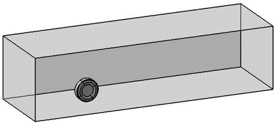
Geometry of the calculation domain.
The wheel is defined as a rotating wall boundary condition. The angular velocity is 63.49 rad/s. Other boundary conditions are listed in Table 1.
Boundary conditions.

Figure 3 displays the volume mesh on the symmetry plane and surface mesh on the wheel. The volume mesh was generated as tetrahedral cells and then converted into polyhedral cells. 13 Prism layers were also generated to obtain reasonable y+ value. Therefore, the wall functions can work correctly when solving the boundary layers. The total amount of cells is 370,000.

Mesh on the symmetry plane and surface mesh on the wheel.
The injection of particles follows the method given by Exa, 5 in which 33 lines are distributed evenly on 340° of the wheel. On each line, 30 particles will be injected in every iteration. What is more, in order to make the simulation more close to the reality, the points are also injected near the wheel bulge contact. Particles are generated on the surface and have initial velocity tangential to the surface of the wheel and equal to the surface speed. The injecting points are shown as black lines and white dots in Figure 4. When the speed of the wind is 80 km/h, the diameter of the droplets can be set at 0.2 mm.5,14
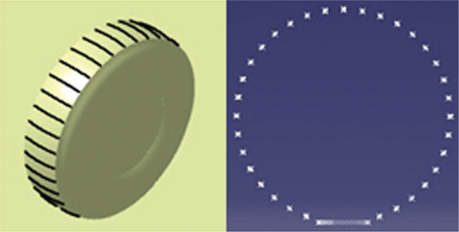
Position of the injecting points.
Both the continuous and discrete phases are treated as unsteady. Achieving a converged steady solution in vehicle external flow simulation is difficult because of several transient characteristics. Droplets can break up and combine during the calculation. The continuous and discrete phases may interact with each other, which can only be realized in an unsteady flow.
In this study, shear stress transport (SST) k-omega was selected as turbulence model because of its excellent performance in predicting the turbulent boundary layer separation. In SST k-omega, blending functions are used to create the zonal formulation, which allows the selection of k-omega and k-epsilon zones automatically to be based on the wall distance. 15
Coupled solver based on pressure was used. The scheme of pressure implicit with splitting of operator (PISO) was selected to deal with pressure–velocity coupling because PISO has better performance than the semi-implicit method for pressure-linked equations in unsteady flow calculation. 16 The time step was 0.0001 s.
Figure 5(a) and (b), from Hucho, 5 shows the experimental data and simulation result by FKFS; Figure 5(c) is the spray picture from this study using ANSYS CFD-Post. To compare Figure 5(a)–(c), the spraying patterns are easily identified to be similar, including the 42° and 35°.
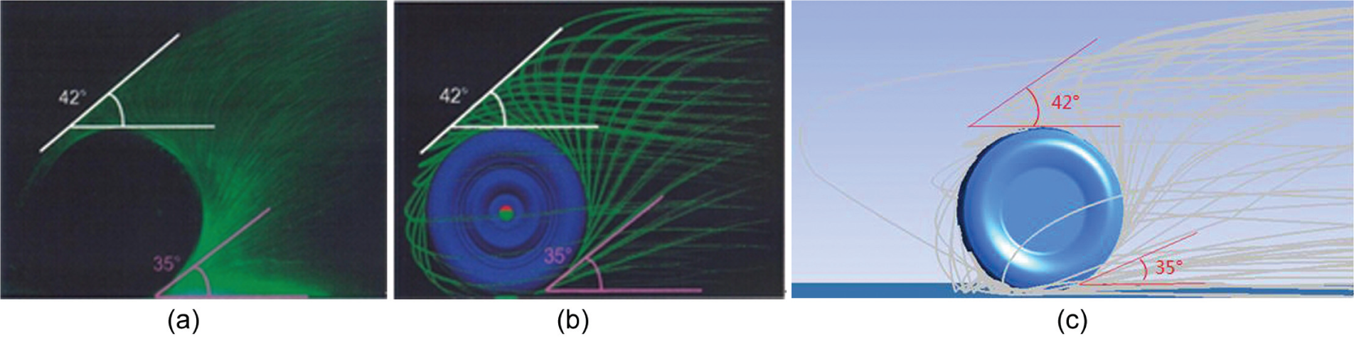
Spray pictures from experimental and numerical simulation: (a)–(c) the green and gray lines are the traces of the droplet. The minimum angle injected into the computational domain and flowed to the distance is 35°. And the maximum angle injected from the wheel surface is 42°.
Simulation of a modified Motor Industry Research Association model
Simulation method
The square-back Motor Industry Research Association (MIRA) model is a vehicle geometry which is used in the CFD simulations. In this study, the rear part of the model was partially cut off to attain better similarity with a common sports utility vehicle (SUV) model. In addition, the structure of wheelhouses was modified. The diameter was 750 mm (whereas the diameter of the wheel was 610 mm). The edges of the wheels were rounded. The radius was 30 mm. Figure 6 presents all modifications. The polyhedral cells are generated with the total amount of 3.4 million, which is displayed in Figure 7.

Standard square-back MIRA model (top) and modified model (bottom) in this article.
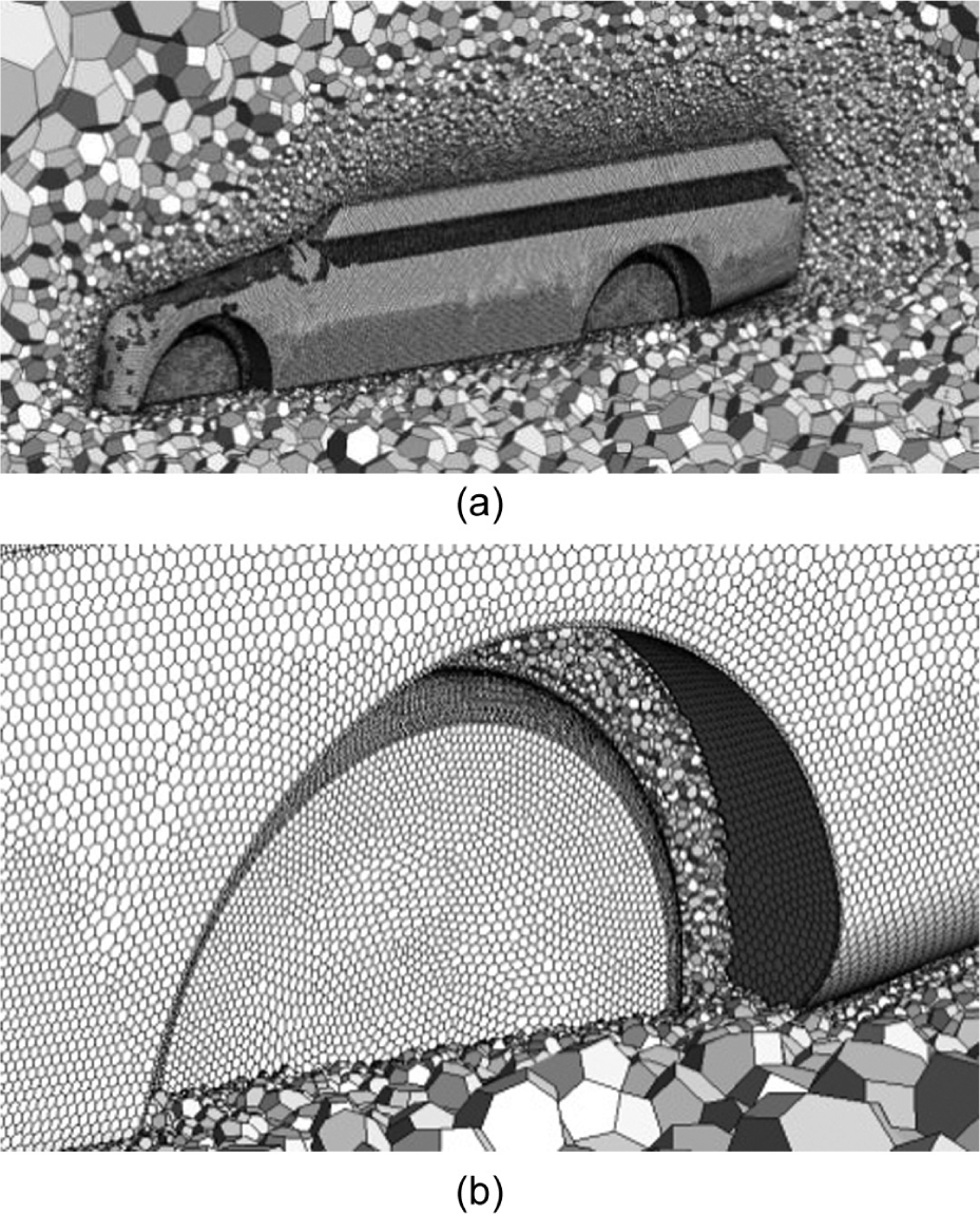
Polyhedral cells around the body and wheel: (a) is the polyhedral cell distribution around the car-body, (b) is the poly-cell between the car-body and the wheel.
The autobody was set as a stationary wall. Moreover, the angular velocity of each wheel was 72.86 rad/s. The boundaries on the calculation domain were the same as shown in Table 1. After several trials, we found that it would be more divergent when the points were emanated from the whole wheel in the MIRA model simulation. In order to compare the results and verify the validity with Gaylard and Duncan, 4 we distributed only 26 lines on 270° of the wheel instead. The number of the particles of each line was same as those in the isolated wheel. In the simulation of wheel spray around a MIRA model, a large number of droplets would be carried by the flow and collide with the body surface. For this reason, the whole body surface was set wall film in the discrete phase calculation to facilitate the simulation. The turbulence model and solution methods were same as those in the isolated wheel simulation.
Soiling pattern and discussion
The soiling pattern on the body surface was achieved upon completion of the calculation. Figure 8 displays the left view (Figure 8(a)), right view (Figure 8(b)), and rear view (Figure 8(c)) of the contaminated body. This figure also shows the scalar of the wall film’s height, which is used as the measurement of contamination in this study. To better display the flow structure around the autobody, three sections are defined and shown in Figure 9.
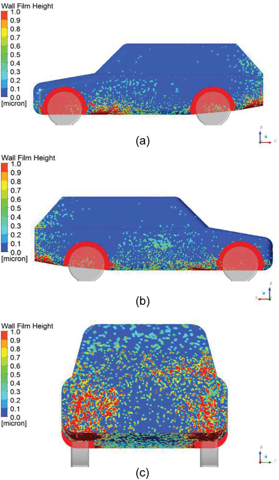
(a) Left view, (b) right view, and (c) rear view of the contaminated body.
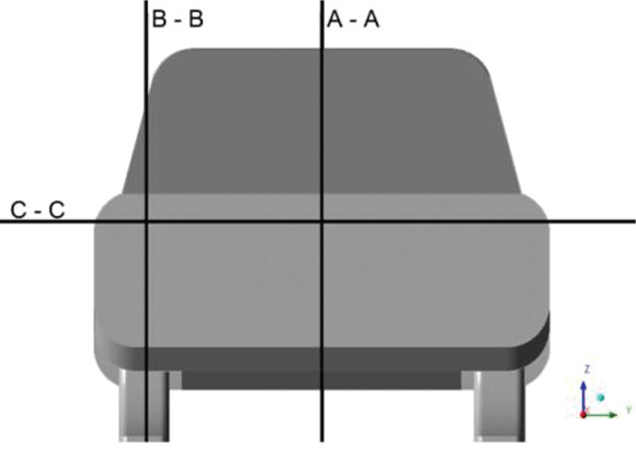
Definition of the three sections.
As a blunt body is exposed to flowing air, a square-back autobody will have exceedingly large vortices in the wake flow because of the blunt tail. Figure 10 shows the streamlines in symmetry section A-A. Two counter-rotating longitudinal vortices are clearly seen, in which the higher vortex is clockwise, whereas the lower vortex is counterclockwise. This movement is in accord with the data in Rob et al. 17 and Mathieu et al. 18
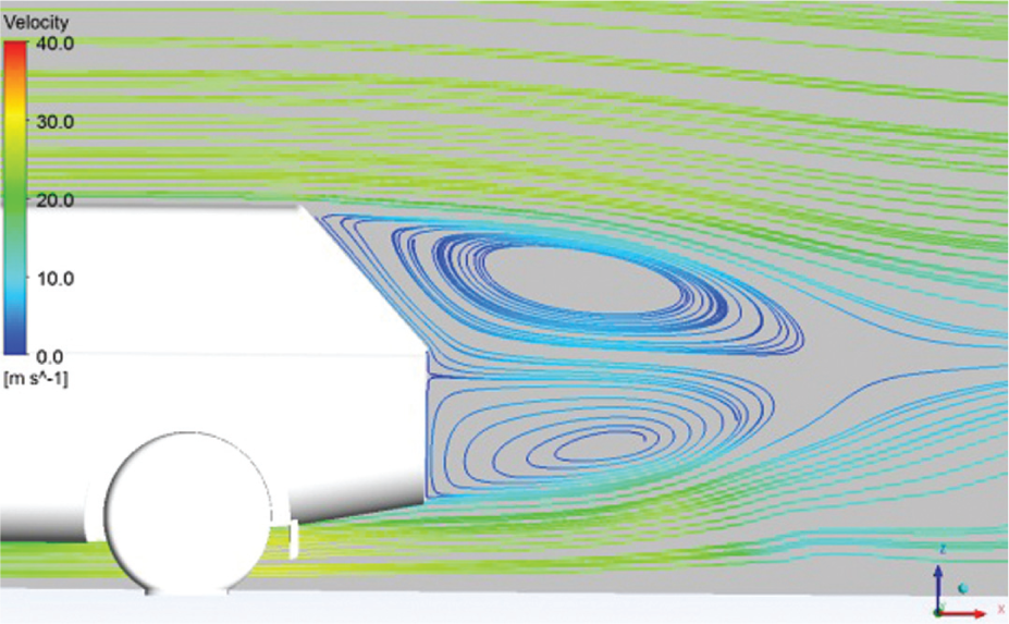
Streamlines in section A-A.
Figure 11 shows the streamlines in section B-B. Two main vortices are also observed. One of the vortices is behind the wheel in the wheel wake, whereas the other vortex is larger and closely attached to the rear vertical surface.

Streamlines in section B-B.
Figure 12 shows that the C-C section behind the autobody is a low-speed area. In this section, two vortices are rolling inward symmetrically. In the low-speed area, the direction of flow is opposite the flow in the high-speed area on the side. Relative clear bounds are observed between the low-speed area and high-speed area.
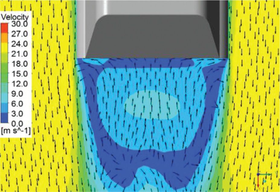
Velocity vectors and contour in C-C section.
The motion of the droplets in the wheelhouse can be extremely complicated and may include problems such as breakup, collision, and rebound. However, when these droplets are carried out of the wheelhouse, the droplets move with the external flow. Figure 13 presents the droplets injected from the right front wheel and streamlines, which emanate from the right front wheelhouse. The droplets are seen to be entrained in the high-speed flow after leaving the wheelhouse and traveling toward the back.

Droplets and streamlines from right front wheel.
The movement of droplets around the body depends on the structure of the vortices. According to Figure 10, a large number of droplets are entrained in the flow beneath the body. These droplets are then mixed with the lower vortex in the wake flow, as shown in Figure 10. The droplets will continue to move in the lower vortex and possibly transfer into the higher vortex. The rolling and transferring motion results in the droplet–wall interaction.
Vortices shown in Figure 11 provide the reason for the wall film’s concentration in Figure 8(c). Droplets in the wheel wake are easily constrained in the lower fixed vortex (Figure 11). When leaving this area, most droplets will be carried into the higher vortex, which provide extremely high probability of frequent wall collision.
According to Figure 12 and above-mentioned discussion on high-speed side flow, droplets traveling near the low-speed area are easily affected and drawn into the low-speed region. For this reason, droplets injected from the front wheel can also be driven to the body wake flow and contribute to the wall film on the rear surface.
Conclusion
Simplified models are used to investigate the numerical simulation method of wheel spray, as well as simulation result based on FVM code with Reynolds-averaged Navier–Stokes equations. Through the DPM model, the Eulerian wall-film model is achieved.
According to the distribution of the wall film, the main contamination areas are the rear face and the bottom side of the body.
The motion of the droplets in the wheelhouse is complicated including breakup, collision, and rebound. The velocity in the wheelhouse is lower than the external flow field. The droplets emanated from the wheelhouse are entrained in the high speed flow and travelled toward the back.
The movement of particles depends on the flow structure and effect of vortex on particle motion.
Finally, particles driven by the vortex would adhere to the autobody surface. The particles in the vortex are one of the most important reasons for surface soiling.
Footnotes
Academic Editor: TH New
Declaration of conflicting interests
The authors declared no potential conflicts of interest with respect to the research, authorship, and/or publication of this article.
Funding
This work was supported by the National Natural Science Foundation of China (grant no. 50805062).