
Abstract
A flexible caudal fin made of the macro fiber composites and the carbon fiber orthotropic composite was investigated by the numerical simulations and the experiments. First, a three-dimensional numerical simulation procedure was adopted to research the torsion propulsion mode of the caudal fin and the impact of the water for the structural torsion frequency of the caudal fin. Then, a two-dimensional unsteady fluid computational method was used to analyze the hydrodynamic performance with the periodic swing of the caudal fin on the torsion mode. Based on the simulation results, the flow field was demonstrated and discussed. The interaction between the caudal fin and the water was explained. Finally, the laser vibrometer system was built to verify the torsion propulsion mode. Meanwhile, the application of the caudal fin was realized on the torsion propulsion, and the measured system was established to demonstrate the performance of the caudal fin. The established simulation procedures and experimental methods in this study may provide guidance to the fins made of the composite materials during the structural design and the investigation of the flow field characteristics with the movement of the fins.
Keywords
Introduction
The eagle hovers freely in the sky, and the fish swims breezily in the limpid water. The natural organism has been an object of the imitation. Bionics is derived from the nature, and the natural inspiration is applied to present new principles and ideas to exploit various devices. Based on the extraordinary swimming ability of the fish in the water and the eager desire of the humankind for the marine resources, the research of the biomimetic aquatic robots is an important direction in the biomimetic field.
The swimming of the fish is realized by the muscular fiber. In view of the scalability of the muscles, the controlled force is produced, and the mechanical work is completed. Figure 1 shows the locomotion of the gold fish. The active caudal fin can realize the active bending deformation as the existence of the muscle, while the passive deformation is achieved without the muscles on the passive caudal fin. According to the feature, a lot of biomimetic aquatic robots are reached. Most fish-like robots have complicated mechanisms using motors and the link mechanism.1,2 With the big volume, the performance of the robots is limited for lack of streamline and flexibility. 3 Therefore, the smart materials have been applied to the fish-like robots such as shape memory alloys (SMAs),4–6 ionic polymer–metal composites (IPMCs),7–9 magnetostrictive thin films,10,11 among other alternatives.12–14 In these literatures, the bending deformation and the undulation similar to the deformation shown in Figure 1 are only studied. In fact, the deformation of the fin is various. The torsion deformation also exists in consideration of the water.

Locomotion of the golden fish.
Macro fiber composite (MFC) as a novel anisotropy composite is developed by NASA. It is made of the aligned rectangular piezoelectric fibers, the structural epoxy, and the intersectional electrode, as shown in Figure 2. It yields better flexibility and impact response and a higher level of strain than conventional piezoelectric actuators. It expands or contracts in the direction of the fiber when an AC voltage (−500 to +1500 V) is applied. The process is similar to the movement of the muscular fiber. In addition, it also has the high efficiency in size and noiseless performance. With the emergence of the MFC, various propulsion modes have been applied to underwater robot.16–20 There exists not only the bending and undulation modes but also some novel propulsion modes. But the active torsion propulsion mode is rarely researched. Moreover, the propulsion modes of the robots are mainly researched using numerical and experimental methods in these literatures, while the hydrodynamic performances on the motion of the caudal fin are rarely analyzed using numerical and experimental methods. In other literatures,21–23 the hydrodynamic performances are mainly numerically and experimentally analyzed without the analysis of the structure. So far, a whole numerical and experimental method has not been found, which includes the analysis of the structure and hydrodynamic performances.
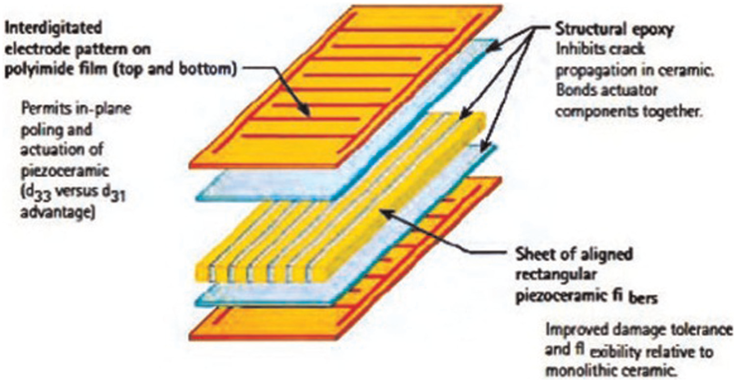
Structure of MFC. 15
In this article, the whole numerical and experimental method is adopted to analyze the locomotion of the caudal fin made of MFCs and the carbon fiber orthogonal composite on the torsion mode in the water. This article is organized as follows: section “Materials and methods” describes the materials and structure of the caudal fin. Meanwhile, the numerical and experimental methods for the torsion propulsion mode of the caudal fin are introduced in the air and water, and the numerical and experimental methods with the motion of the caudal fin are also introduced. In section “Results and discussion,” the detailed numerical and experimental results of the caudal fin are presented and discussed. Moreover, the caudal fin is applied to the micro aquatic robot, and the experimental research is discussed. Finally, the work is concluded with some remarks.
Materials and methods
Materials and structure of the caudal fin
Based on the former studies, it is essential to unite the MFC with the substrate for the large deformation of the caudal fin. The carbon fiber orthogonal composite is utilized as the substrate here. In line with the consistency principle of the main fiber direction, two pieces of the entire MFC are pasted on both sides of the carbon fiber orthogonal composite plate by high shear epoxy adhesion bonding. In order to increase the torque and reduce the drag, the structure of the caudal fin is shown in Figure 3. Table 1 shows the properties of the materials for the numerical simulation.

Structure scheme of the caudal fin.
Properties of materials.

MFC: macro fiber composite.
Numerical simulation procedures
The locomotion of the aquatic robot is the production of the interaction between the active vibration of the caudal fin and the water. First, the structural numerical methods are used to discuss the frequencies of the torsion propulsion modes and the influence of the water for the structural vibration. Then, the fluid numerical methods are adopted to analyze the hydrodynamic performances on the torsion propulsion mode and the reactive force for the caudal fin.
Structural numerical methods
According to the structure of the caudal fin, the numerical simulations of the caudal fin are carried out using the COMSOL Multiphysics software. The piezoelectric module is adopted. The caudal fin is similar to the cantilever beam, considering the big stiffness of the genuine fish body. The boundary condition is shown in Figure 3. The left side is clamped. The two pieces of MFC are applied with two sinusoidal AC voltages out of temporal phase by 180°. The nonlinear of the geometric is adopted because of the large deformation of the caudal fin.
Sader and co-workers24–27 accounted for the hydrodynamic effects on atomic force microscopy cantilevers. It is significant to have an impact on the frequencies in the fluid. To verify the impact on the natural frequencies of the caudal fin in the water, the structure–fluid model consisting of structural elements and fluid elements is established. The sound-piezoelectric module is adopted to calculate the natural frequencies. The density of the water is 1000 kg/m3, and the acoustic velocity is 1480 m/s. The no-slip condition for the boundary layers is imposed over the walls.
Fluid numerical methods
The unsteady incompressible flow equations are solved for the flow passing through the movement of the caudal fin. The basic equations are the following continuity, momentum, and energy equations, respectively
where
The numerical simulations of the hydrodynamic performances are carried out using the commercial software, COMSOL Multiphysics. The finite volume method is used for the discretization of governing equations (continuity equation and momentum equation) in the space region. The unsteady calculation is initialized from the solution of a steady calculation. For the unsteady calculation, the sliding mesh technique is applied to simulate the interaction of the caudal fin. The interface between the caudal fin and the water is set as general grid interface, and it is defined by the swing displacement of the caudal fin.
The total force

where


where
Experimental methods
Vibration measured methods
In order to verify the numerical methods of the caudal fin, a laser Doppler vibrometer system is established to measure the vibration characteristic of the caudal fin. The caudal fin fixed by the clamp in the air is flat on the platform, and the surface of the MFC is measured to effectively obtain the vibration mode, as shown in Figure 4. The density of the water is greater than the density of the air. The above measured method is not fit to measure the vibration characteristic in the water. Therefore, a three-dimensional laser Doppler vibrometer system is built, as shown in Figure 5. The caudal fin fixed by the clamp is perpendicular to the water. The surface of the caudal fin along the thickness is located on the surface of the water, and the thin reflective paper is posted on the surface of the thickness. The coordinate systems of the three laser Doppler vibrometers satisfy the orthogonal conditions of the two coordinate systems.

Measured area of the caudal fin.

Three-dimensional laser Doppler vibration system.
Hydrodynamic experimental methods
The locomotion of the biomimetic fish is mainly realized by the thrust at the caudal fin. In order to research the thrust, the lever principle is used to measure the underwater thrust. Figure 6 shows the diagram of the measurement device. The aluminum bars are applied to the lever structure. The caudal fin is submerged in water and fixed to the aluminum bar, and the proportion of the amplification is 1:20. The force sensor is adopted to measure the amplifying force. The driving voltages for the MFC are 700 and 800 Vpp without DC offset and 900 Vpp with the DC offset. The frequency range is chosen with a fine increment of 0.5 Hz, according to the movement of the aquatic robot on the vibration mode.

Experiment diagram of underwater mean thrust.
Results and discussion
Structural vibration characteristics in the air and water
Figure 7 shows the calculated eigenfrequency results of the caudal fin in the air. It can be seen that there exists the first-order bending mode, the first torsion mode, and the second bending mode. The eigenfrequencies are around 12.7, 103.6, and 183.3 Hz, respectively. So as to verify the validity of the calculation, the vibration characteristics of the caudal fin are tested in the air. The experimental frequency response is shown in Figure 8(a). The experimental eigenfrequencies are around 14.25, 103, and 135.5 Hz in the air. In Figure 8, different colors mean distribution of structure deformation: “red” is upward, “green” is downward, and “black” is middle. Comparing the calculated results shown in Figure 7 with those shown in Figure 8, the experimental results confirm the finite element method (FEM) vibration modes. The error of the frequencies is produced due to the effect of the glue used to bond the MFC and the carbon fiber orthogonal composite. As a consequence, the model is confirmed. In addition, not only the torsion mode but also the bending mode and the undulatory mode exist in the caudal fin. Compared with other smart materials, there are various patterns of the deformation.

Calculated eigenfrequencies of the caudal fin in the air: (a) the first-order bending mode, (b) the first-order torsion mode, and (c) the second-order bending mode.

Experimental measured vibration results in the air: (a) the velocity versus frequency, (b) the first-order bending mode, (c) the first-order torsion mode, and (d) the second-order bending mode.
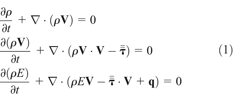
In view of the effect of the water for the structural frequencies, the vibration eigenfrequencies are calculated in the water, as shown in Figure 9. The eigenfrequencies are around 3.1, 25.1, and 41 Hz, respectively. Comparing the frequencies shown in Figure 9 with those shown in Figure 7, it is seen that the natural frequencies decline about 75% on account of the effect of the water. It is obvious that the water has a significant impact on the natural frequencies of the flexible structure by the calculation. Similarly, the vibration testing experiment in the water is done. Figure 10(a) shows the frequency response of the caudal fin in the water. The frequencies are around 25.4 and 32.4 Hz. In Figure 8, the measured first-order bending frequency in the air is around 14.25 Hz. Hence, the first peak of the frequencies in the water stands for the first-order torsion frequency. Compared with the results (Figure 8), the frequencies also decline about 75%. It is confirmed that water has a significant impact on the natural frequencies and therefore cannot be neglected for the influence of the vibration. Furthermore, it is observed that the structure–fluid model is verified by the experimental results.

Calculated eigenfrequencies of the caudal fin in the water: (a) the first-order bending mode, (b) the first-order torsion mode, and (c) the second-order bending mode.
Experimental measured vibration results in the water: (a) the velocity versus frequency, (b) the first-order torsion mode, and (c) the second-order bending mode.
The vibration of the caudal fin at 25.1 Hz and 900 Vpp driving voltage by FEM in the water is shown in Figure 11. It is seen that the torsion propulsion mode is excited in the caudal fin. Moreover, it is noted that the displacement in the Y direction is maximal, and according to the experimental phenomena in Figure 10(b), the curve along the length is similar to the curve of the first-order bending vibration. In consequence, the two-dimensional model is used to approximately discuss the hydrodynamic performances during a cycle of the caudal fin.

Calculated displacement at 25.1 Hz and 900 Vpp in the water: (a) calculated total displacement, (b) displacement in x direction, (c) displacement in y direction, and (d) displacement in z direction at 25.1 Hz and 900 Vpp in the water.
Hydrodynamic performance
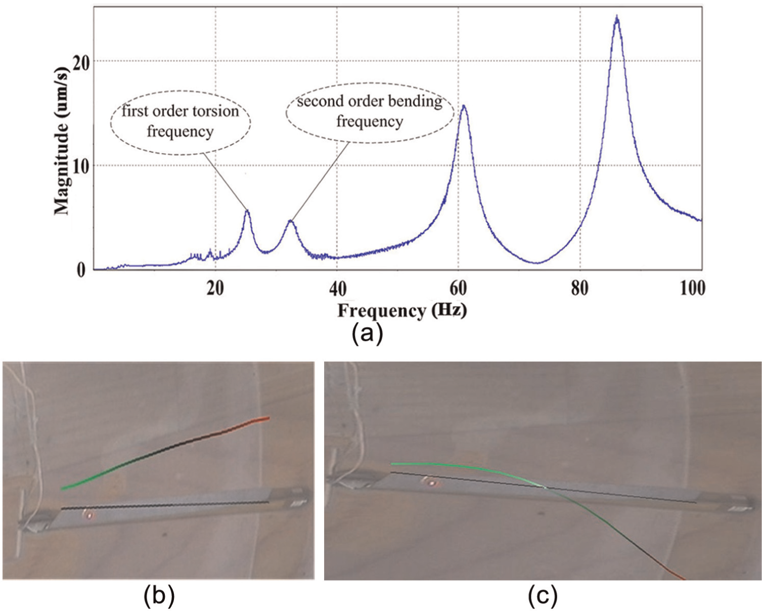
The pressure nephogram is shown in Figure 12 during a periodic movement of the caudal fin. Due to the effect of the surface normal pressure gradient, the larger pressure difference occurs at the maximum displacement of the caudal fin. The flow velocity and the reaction force are mainly contributed by the pressure and are closely related to the pressure distributions over both the sides of the caudal fin. The caudal fin swings symmetrically about the chord. At t = 0 and t = T/2, the caudal fin lies on the equilibrium position. At t = T/4 and t = 3T/4 (T: oscillation period of the caudal fin), the caudal fin lies on the maximum position. The pressure nephogram of the flow field at t = T/4 and t = 3T/4 reveals that the negative pressure regions are more intense than the positive pressure regions. The pressure difference is the largest and acts to pull the caudal fin upstream or downstream. Flow velocity nephogram of the flow field reveals that the flow velocity is largest at t = T/4 and t = 3/4 in Figure 14. Besides, the maximum thrust is generated. Following with the declining of the pressure difference, the thrust is declining. The minimum thrust occurs when the difference is very small.
Pressure nephogram of the flow field during a periodic movement of the caudal fin: (a) at t=0, (b) at t=T/4, (c) at t=T/2, and (d) at t=3T/4.
Figures 13 and 14 illustrate the changes in the vorticity contours and flow velocity during one cycle. In consideration of the high oscillation frequency of the caudal fin, the oscillation amplitude is smaller. The generation and shedding process of the vorticity exists, even if it is not obvious for. At t = T/4 and t = 3T/4, the caudal fin lies on the maximum position. The vorticity and the flow velocity are maximum. As a result, the whole vorticity is formed. Following with the change in the swing direction, the vorticity sheds. The vorticity and the flow velocity are decreasing. Meanwhile, the new vorticity generates. The swing direction changes twice during one cycle. Therefore, the generation and shedding process of the vorticity occurs twice. Similarly, the flow velocity occurs twice during one cycle.
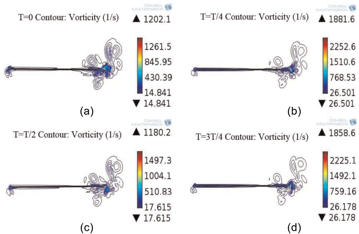
Vorticity nephogram during a periodic motion of the caudal fin: (a) at t=0, (b) at t=T/4, (c) at t=T/2, and (d) at t=3T/4.

Flow velocity nephogram during a periodic motion of the caudal fin: (a) at t=0, (b) at t=T/4, (c) at t=T/2, and(d) at t=3T/4.
Figure 15 shows the time averaged nondimensional thrust coefficient and lateral force coefficient in a cycle. The caudal fin swings symmetrically about the chord. It is seen that it is similar to the change in the thrust between the positive range and the negative range. Therefore, the mean thrust coefficient is smaller, and it is 0.001. In addition, it is found that there are two periodic changes in the thrust coefficient and a periodic change in the lateral force during a periodic swing of the caudal fin. It illustrates that the thrust is affected by the vorticity, while the lateral force derives from the pressure change on the surface of the caudal fin.

Thrust coefficient and the lateral force coefficient during a periodic motion of the caudal fin: (a) thrust coefficient and (b) lateral force coefficient during a periodic motion of the caudal fin.
In terms of the experimental principle shown in Figure 6, the mean thrust is investigated experimentally and theoretically. The resulting mean thrust frequency response curves are shown in Figure 16. The maximum experimental mean thrust is 11 mN at 900 Vpp at 28.5 Hz. The frequencies away from the resonance frequency region are prone to the measured structural vibration. Note that the thrust first increases and then decreases with the increasing frequencies, although the results undulate as shown in Figure 16. In conclusion, the numerical simulation can predict the change in the flow field during the motion of the caudal fin.

Measured and calculated mean thrust for different peak-to-peak voltage inputs of (a) 700 Vpp, (b) 80 Vpp, and (c) 900 Vpp.
Application of the caudal fin
In order to realize the application of the caudal fin, the aquatic robot is designed by the low density float and a mass used to constrain the amplitude of the head end. The structure is similar to the cantilever. And it is necessary to balance between the gravity and the buoyancy by the float so as to stabilize the body in water vertically. The robot swims in the sink which is 1 m long and 0.5 m wide. The locomotion process of the aquatic robot is recorded by the camera for the analysis of the locomotion velocity. The flow velocity at the locomotion of the robot is measured to research the flow field around the robot. The diagram of the experimental device is shown in Figure 17. The Unidata STARFLOW 6526 is used to measure the flow velocity and put in the bottom of the sink.
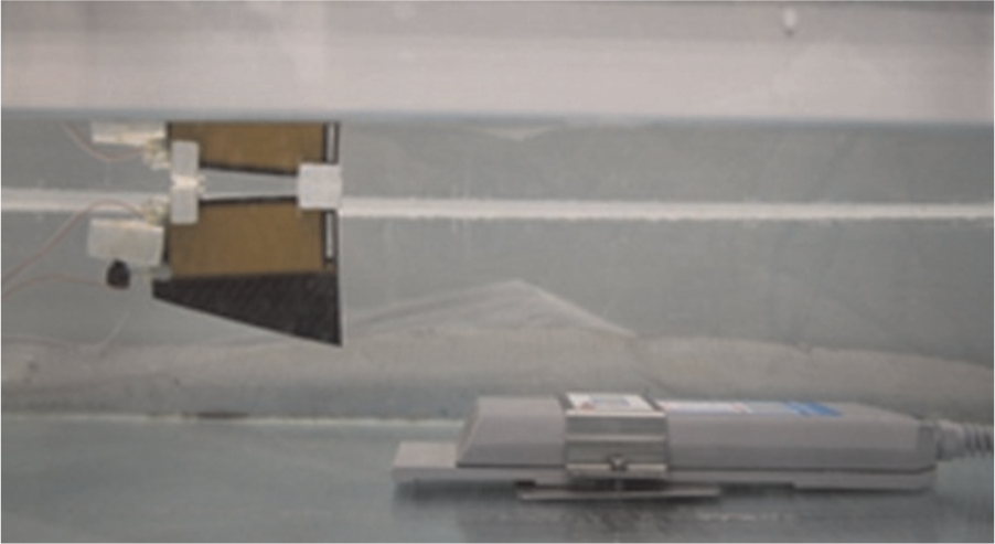
Experiment of the flow velocity.
Figure 18 shows the results of the locomotion velocity of the robot and the flow velocity in the sink. Note that the maximum locomotion velocity and flow velocity are 322 and 268 mm/s at 26 Hz and 900 Vpp, respectively. The frequencies away from the resonance frequency region are prone to the structural effect of the robot. It is found that the curves are similar between the locomotion velocity and the flow velocity. Similarly, the locomotion velocity and the flow velocity first increase and then decrease with the increasing frequencies. As shown in Figure 18, it can be conclude that there exists the interaction between the robot and the water.
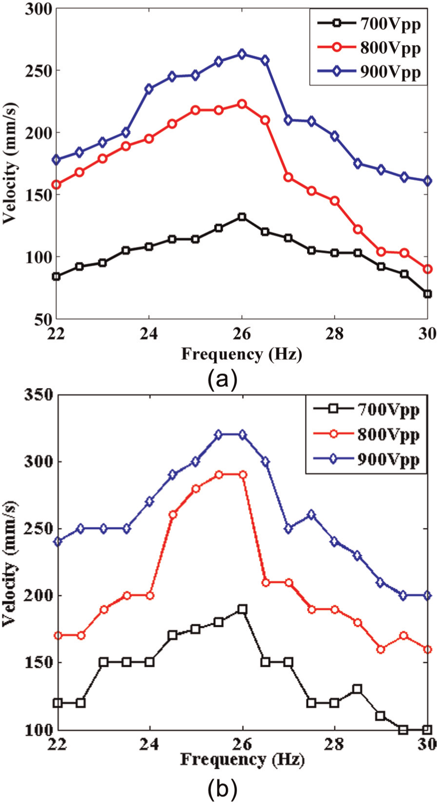
(a) Experimental locomotion velocity of micro bionic fish robot and (b) experimental flow velocity curves.
Concluding remarks
A novel flexible caudal fin using MFCs and the carbon fiber orthogonal composites is investigated theoretically and experimentally. The numerical simulations of the caudal fin have been carried out based on the FEM and the fluid numerical. The representative characteristics of the structure and flow field have been successfully captured, which mainly include the following:
There are not only the existence of the bending and undulating propulsion mode but also the existence of the torsion propulsion mode on the caudal fin.
There is a more significant influence on the structural frequencies in the water.
The interaction process of the caudal fin and the water is demonstrated on the torsion frequency in the closed sink. The change in the pressure, flow velocity, and vorticity is periodic with the periodic swing of the caudal fin. The thrust generation of the caudal fin is affected by the vorticity, while the lateral force derives from the pressure change on the surface of the caudal fin.
Then, the experiments of the laser vibrometer and the locomotion of the aquatic robot verify the numerical simulations, and the application of the composite materials is realized on the biomimetic robot. Therefore, the demonstrated numerical simulation and experiment procedure is of typical reference to the related field, and the results can be used for further optimal design of the caudal fin using the composite materials.
Footnotes
Academic Editor: Guoqiang Li
Declaration of conflicting interests
The authors declare that there is no conflict of interest.
Funding
This work was supported by the Natural Science Foundation of China (no. 5175250), the Funding of Jiangsu Innovation Program for Graduate Education and the Fundamental Research Funds for the Central Universities (no. CXLX12_0144), and the Priority Academic Program Development of Jiangsu Higher Education Institutions (PADA).