
Abstract
Accurate and robust lane detection, especially the curve lane detection, is the premise of lane departure warning system and forward collision warning system. In this article, an algorithm based on improved river flow and random sample consensus is proposed to detect curve lane under challenging conditions including the dashed lane markings and vehicle occlusion. The curve lanes are modeled as hyperbola pair. To determine the coefficient of curvature, an improved river flow method is presented to search feature points in the far vision field guided by the results of detected straight lines in near vision field or the curved lines from the last frame, which can connect dashed lane markings or obscured lane markings. As a result, it is robust on dashed lane markings and vehicle occlusion conditions. Then, random sample consensus is utilized to calculate the curvature, which can eliminate noisy feature points obtained from improved river flow. The experimental results show that the proposed method can accurately detect lane under challenging conditions.
Introduction
As a fundamental part of intelligent transportation systems (ITS), the method of obtaining and identifying information about the road by intelligent vehicles plays a very important role in ITS, and lane detection is a prerequisite for realizing lane departure warning and forward collision warning, which are also the key technologies for achieving intelligent vehicle vision aided. 1 Lane detection comprises the straight lane detection and the curve lane detection. In most lane detection modules, lane markings are processed as straight lines, and the lane curvature cannot be obtained; therefore, false alarms will be generated in a collision warning system. For example, without knowing the road curvature, the system cannot distinguish objects on the other lanes (e.g. the vehicle) from the objects on the same lane, and it may generate a false alarm. Therefore, we should achieve an accurate curve lane detection instead of straight lane detection, especially in some challenging scenarios, such as the dashed lane markings and vehicle occlusion.
Due to the importance of lane detection, researchers carried out a great deal of researches on lane detection. In general, vision-based lane detection can be categorized into two main classes. One is the feature-based method,2–5 which can distinguish the feature points of lane markings from the points of nonlane markings by the feature of road image, such as the color, the width, and the edge of lane. Chiu and Lin 2 proposed a method of color segmentation, which mainly uses threshold processing following the color and fitting with a quadratic function. Kluge 3 proposed road detection method based on the automated road curvature and direction estimation (ARCADE) algorithm. Murphy-Chutorian and Trivedi 4 exploited the shape information of each region as well as the texture inside it based on the Maximally Stable Extremal Regions (MSERs) 5 for lane detection. One problem of this method is the extraction of edge point locations and orientations from an image. These feature-based methods are easy to implement, but require clear lane markings, which are hard to obtain under challenging scenarios, and it is sensitive to the surrounding environment.
The other kind of methods is model based.6–10 The key part of this kind of methods is to determine a mathematical model according to the shape of the road. The parameters of the mathematical model are solved according to the feature points of lane markings from a road image. However, the difficulty in this kind of method is the extraction of feature points of lane markings from a road image, especially under some challenging conditions, such as the dashed lane markings and vehicle occlusion.
For example, Wang et al.6,7 proposed a method for lane detection and tracking based on cubic B-Spline curve. The feature points of lane markings are extracted by Canny edge detection and Hough transform. In the work by Chen and Wang, 8 a real-time lane detection algorithm based on a hyperbola-pair model is proposed. They think that some parameters of the model are the same in the case of parallel lanes on the same road. This considerable insight is also used in our algorithm. A search strategy of mid-to-side is used to extract the feature points of lane markings. Jung and Kelber9,10 used a linear parabolic model for each lane boundary. The linear part is used to fit lane marking in the near vision field. The parabolic part of the model, which fits the far field, is then used to analyze the geometry of the road ahead (straight, right curve or left curve). In this method, a combination of the edge distribution function and a modified Hough transform is used to extract the feature points of lane markings. However, there still exist limited studies on robust and accurate methods to extract the feature points of lane markings, especially in the far vision field. Using the traditional methods to deal with the conditions such as dashed lane markings and vehicle occlusion, some unpredictable results may occur.11,12 Vehicle detection13,14 can improve the property of lane detection. Several curve lane detection methods combined with vehicle detection were proposed by Wang et al., 15 Lim et al., 16 Choi et al., 17 and Sivaraman and Trivedi, 18 which can better get rid of vehicle occlusion. Nevertheless, the complexity of these methods is too high. And there are limited studies on searching feature points of curve lane in the far vision field.
In order to achieve robust lane detection with dashed lane markings and vehicle occlusion, some lane-tracking methods have been proposed19–22 based on particle filter23,24 due to its promising property of handling nonlinear and non-Gaussian systems. However, the good property of lane-tracking methods also depends on robust lane detection algorithm.
In fact, a good lane detection algorithm should satisfy some challenging scenarios.25–27 However, the feature points on the curve lane markings are difficult to obtain in the far vision field. In this article, a robust method based on improved river flow (IRF) and random sample consensus (RANSAC) is proposed which can work in some challenging conditions. The IRF can help accurately search feature points on the curve lane by the results of detected straight lines in near vision field or the curved lines from the last frame, which can connect dashed lane markings or obscured lane markings. RANSAC is used to fit the curve lane by the searched feature points.
The remainder of this article is arranged as follows: section “Straight lane detection” describes the hyperbola-pair model and introduces how to detect the straight lane on the near vision field. IRF is used to search feature points on curve lane and fitting with RANSAC in section “Curve lane detection.” Section “Experimental results” discusses the relevant experiment results and analysis. Finally, conclusion and future development are mentioned.
Straight lane detection
Framework of lane detection
Figure 1 shows the flow diagram of lane detection. The region of road on the front of vehicle is divided into two parts. One is the straight region in the near vision field; the other is the curve lane in the far field (Figure 2). A top view of road image is obtained by offline camera calibration and inverse perspective transformation in the near vision field. The parameters

Flow diagram of algorithm.

Division of lane region: region 1 is the region of road in the near field, and region 2 is the region of road in the far field.
Hyperbola-pair lane model
According to the model proposed in Chen and Wang,
8
the hyperbola-pair road model corresponds with the road model of parallel parabolas in ground plane. For an arbitrary point of
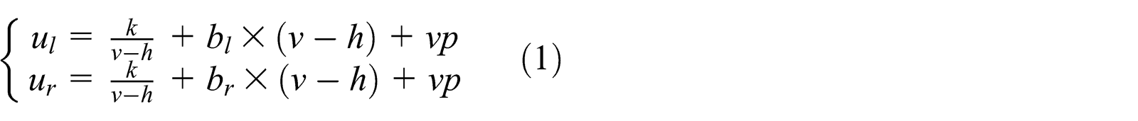
Table 1 shows the variables used in curve lane detection. Thus, we solve all the above parameters instead of detecting lane markings. With the increase in

Variables used for curve lane detection.

Comparing equation (1) with equation (2), we can know that if we have detected the straight lane marking in the near field, the parameters

Relationship between straight line and curved line.
Local Hough transform
Hough transform is a common method of line detection. In the method by Aly, 28 a local Hough transform method is used to detect and count how many lines there are in the top view road image and then RANSAC algorithm is used to fit based on Bézier Splines. Referred to this method, in this article, local Hough transform is used to detect the straight lane in the near vision field. First, a region of interest (ROI) in the near field is selected as a subimage (Figure 4(a)). Next, inverse perspective transformation with an offline camera calibration in Tan et al., 29 is applied on the subimage to obtain the image of inverse perspective transformation. As shown in Figure 4(b), the lane markings are parallel on the inverse perspective transformation.

Inverse perspective transformation of road image: (a) a region of interest and (b) image of inverse perspective transformation.
The transformed subimage is then filtered by a two-dimensional Gaussian kernel. The vertical direction is a smoothing Gaussian, whose


(a) Subimage after filtering and binarization and (b) sum of pixels of each column.
SumPixel which is the sum of pixels of each column is counted on the subimage after filtering and binarization (shown in Figure 5(b)). If SumPixel > Th (
According to the location where the lane marking may be located on, a local Hough transform, which needs less computing time and interference than the global Hough transform, is used to detect line around the corresponding location (shown in Figure 6). Assuming the detected lane can be approximated as a straight line, the model of polar coordinates can be expressed as follows


Line detection with a local Hough transform.

Result of straight lane detection in the near vision field.
Curve lane detection
In this study, the model of curve lanes is based on hyperbola-pair model in which the coefficient of curvature is determined by our proposed method based on IRF method and RANSAC, while other parameters are determined by the straight lines. IRF method, which can better search feature points in the far vision field of curve lane under challenging scenarios, such as the dashed lane markings and vehicle occlusion, is utilized such that the feature point is searched according to the straight line and curved line from the last frame. In this section, the IRF and RANSAC are proposed to determine the coefficient of curvature
IRF
In the far vision field, the feature points on the lane markings are difficult to obtain by edge detection or Hough transform, especially under some challenging scenarios such as the dashed lane markings and vehicle occlusion. Lim et al. 30 proposed a search method based on river flow, which can search for feature points on curve lane in the far vision field. But the method is only applicable to continuous lane markings, the process of searching will be stopped and cannot search feature points in the far vision field of curve lane in the conditions of the dashed lane markings and vehicle occlusion; thus, an unpredictable and even the false result occurred. To overcome this problem, in this article, an IRF method, which can better search feature points in the far vision field of curve lane under challenging scenarios, such as the dashed lane markings and vehicle occlusion, is proposed to search feature points on the curve lane. The key of the IRF is that it can connect dashed lane markings or obscured lane markings according to the results of detected straight lines in near vision field or curved lines from the last frame. Thus, the process of searching cannot be stopped. The specific steps are as follows:
Step 1: The pixel values of the straight line extended to far vision or the curved line detected by the last frame image are set to 0.5 as shown in Figure 8;
Step 2: The process of search starts from a start flowing point P (the top point on the detected straight lane markings in the near field);
Step 3: Comparing the pixel values of points around this point with a mask 4 × 2 (Figure 9) and choose the feature point which has the maximum pixel value;
Step 4: The searched point in step 3 is used as the temporal start flowing point;
Step 5: Repeating steps 3 and 4 until the end of searching.

(a) Directed straight line of searching feature points (gray line) and (b) directed curved line of searching feature points (gray line).

Mask 4 × 2 to obtain nearby pixels: (a) mask of right lane and (b) mask of left lane.
Figure 9 is the mask 4 × 2 to obtain nearby pixels. Figure 9(a) is the mask of right lane that can better obtain the far left feature points for the right lane markings. In the same way, Figure 9(b) is the mask of left lane that can better obtain the far right feature points for the left lane markings. If the point

The following are some constraints:
Due to the application of lane detection, reversion of the point flow is prohibited. The lane flow is either moving forward or moving in the same row of current detected pixel;
An arbitrary point of higher pixel will be selected if two or more same higher pixel values existed in the next flow;
The flowing process might halt if all the pixel values around the target point are zero or the target point is on the horizon.
The result of searching feature points on curve lane by IRF is shown in Figure 10. In the video sequences, we can search for feature points using the curved line which is the result of hyperbola-pair model of the last frame. Thus, the result will be more accurate than the straight line (Figure 10(b)). Figure 11(a) shows the result of searching feature points without using the directed straight line (red points), and the process of search will be stopped in the dashed lane markings. Figure 11(b) shows the result of searching feature points using the directed curved line (red points), and it can complete the process of search perfectly in the dashed marking.

(a) Result of searching feature points by the directed straight line and (b) result of searching feature points by the directed curved line.

(a) Result of searching feature points without using the directed straight line (red points) and (b) result of searching feature points using the directed curved line (red points).
Fitting with RANSAC
RANSAC is used to calculate the parameters of the mathematical model by a sample dataset comprising a set of abnormal data. It was first proposed in 1981 by the Fischler and Bolles. 31 RANSAC is one of the widest used robust regression algorithm in computer vision. In our experiments, some noise points may be searched by the IRF method, especially under some challenging conditions including the dashed lane markings and vehicle occlusion. RANSAC method, which is used to estimate parameters of a mathematical model from a set of observed data with outliers, is suitable for our work. It fits curve lane feature points perfectly and meets requirements of robustness and accuracy in our experiments.
The feature points obtained by IRF on left lane markings are
Step 1: For the set
Step 2: Calculate the distance between each feature point and the left hyperbola, and if the distance is less than a certain threshold t, the feature point is the inner point and mark the number of inner points;
Step 3: Repeat
Step 4: For the set
Step 5: Calculate the number of inner points with the model of hyperbola pair; when the parameter
It should be noted that the times

Result of curve lane detection.
Experimental results
The proposed method is tested on numerous conditions, including solid and dashed lane markings, straight and curve lanes, blurred lane markings, vehicle occlusion, and road marks. The experimental video clips are downloaded from http://www.youtube.com/watch?v=qQHDvlsLu4c. The results of our experiment indicate the good performance of our algorithm for curve lane detection, especially under some challenging scenarios including the dashed lane markings and vehicle occlusion.
The information of video sequence is used to better achieve curve lane detection. The performance of curve lane detection depends on the straight lane detection in the near vision field. There are some strategies that are used in the straight lane detection:
The filtering of multiple lane markings: The result of detection will appear for multiple lane markings because of the width of lane marking or the intersection of multiple lane markings (Figure 13(a)). So, the lane markings which are located in the inside of lane will be chosen (Figure 13(b));
The width of single lane: This is a constant value on the structured way. So, we use the width of single lane to validate the result of the straight lane detection. Figure 14(a) shows the false result of straight lane detection in the near vision field because of the middle road marks. The correct result of lane detection can be obtained by the width of single lane and the information of the last frame (Figure 14(b));
The result of straight lane detection in the near vision field cannot be obtained if there are no lane markings in the ROI because of the dashed lane markings (Figure 15(a)). At this time, the result of the last frame will be treated as the result of this frame (Figure 15(b)).

(a) Result of straight lane detection before filtering and (b) result of straight lane detection after filtering.

(a) Original result of straight lane detection and (b) result of straight lane detection after correcting.

(a) Missing of lane marking in the ROI and (b) result of straight lane detection after using the information of video.
Figure 16(a) and (b) shows the result of two consecutive frames of the curve lane detection with the original river flow, and when a false detected result occurred under dashed lane markings, the coefficient of

Result of curve lane detection: (a and b) original river flow and (c and d) improved river flow.
Vehicle occlusion is a knotty problem in lane detection, especially when the color of vehicle is similar with lane markings. Some wrong points may be searched by IRF under this phenomenon without vehicle detection (shown in Figure 17(a)). So, vehicle detection is important and necessary. The comparison results of lane detection with and without vehicle detection are shown in Figure 17. The results show that the lane detection performance can be promoted by vehicle detection.

(a) Result of curve lane detection without vehicle detection (red points are the feature points) and (b) result of curve lane detection with vehicle detection.
Figure 18 shows some conditions of curve lane detection, Figure 18(a)–(c) shows the detection results of a combination of solid lane markings and dashed lane markings, and part of lane markings are blurred and have middle road marks. The intersection of multiple lane markings appears in Figure 18(d)–(f). Dashed lane markings are also detected accurately by the IRF and video information (Figure 18(g)–(i)). Figure 18(j)–(l) shows the case of vehicle changing lanes. In the case of vehicle occlusion (Figure 18(m)–(o)), the lane markings are detected by vehicle detection and IRF. From the results, it is found that the proposed method can robustly and accurately detect both straight line and curved line under some challenge conditions.

Some results of curve lane detection: (a)–(c) are results on the combination of solid lane markings, dashed lane markings, and the middle road marks. Part of these lane markings are blurred. The intersection of multiple lane markings appears in (d)–(f), (g)–(i) are the detection results on dashed lane markings, (j)–(l) show the detection results which include some cases of vehicle changing lanes, and (m)–(o) show the detection results in the case of vehicle occlusion.
Conclusion
In this study, we introduced a robust real-time lane detection algorithm based on IRF and RANSAC for local roads and freeways of some challenging scenarios, such as the dashed lane markings and vehicle occlusion. A robust feature point search method by IRF has been proposed, which can better search feature points in the far vision field of curve lane under challenging scenarios. RANSAC can fit lane markings fast and accurately by these feature points.
The results of test indicate that our algorithm is robust and meets the requirement of accuracy, and it can provide good information of current lanes for driver and is suitable for lane departure warning system (LDWS) and forward collision warning system (FCWS). The future works should focus on the lane-tracking methods and vehicle detection with tracking methods to promote the lane detection performance.
Footnotes
Academic Editor: Ruey-Jen Yang
Declaration of conflicting interests
The authors declare that there is no conflict of interest regarding the publication of this article.
Funding
This work was supported by Open Fund of State Key Laboratory of Automotive Safety and Energy, Tsinghua University (KF14031) and partly supported by National Natural Science Foundation of China (61271376), National Basic Research Program of China (973 Program: no. 2012CB725405).