
Abstract
This article presents the development of configurations for bio-inspired self-healing cellular arrays known as Embryonics (embryonic electronics). In the Embryonics design, the configurations are employed to define the functionality and connections of each cell. However, developing configurations of the Embryonics is a time-consuming and challenging work due to lack of effective tools. In this article, an approach is proposed to develop configurations using graphic mapping, which also optimizes the length of configurations for the Embryonics. Using metric embedding, the problem of configurations is exactly formulated to binary quadratic assignment problem and routing problem with constraint of the Embryonics architecture. Since binary quadratic assignment problem is nondeterministic polynomial-time hard, a genetic algorithm is used to tackle this problem for achieving high-quality placement. Due to the limitation of communication bandwidth, how to resolve congestion is also an important issue. An improved ant colony algorithm is presented to realize routing of the Embryonics based on the result of placement. Configurations of the Embryonics are formed according to the result of placement and routing. Experimental result on a
Introduction
The reliability of electronic systems has always been an issue with electronic engineering. Common ways to improve the reliability, such as dual modular redundancy and triple modular redundancy, usually have high resource overhead and poor fault-coverage. 1 Embryonics (embryonic electronics) is a promising alternative to design highly robust integrated circuits.2,3 It aims to make the digital hardware obtain some of the features of biological organisms such as self-replication and self-repair. However, designing an Embryonics system is a hard job due to lack of computer-aided design (CAD) tools. In its present state, Embryonics is usually implemented using field programmable gate array (FPGA). It synthesizes and simulates using FPGA design software such as Xilinx ISE Foundation. However, the early stages of designing Embryonics have to specify the function and connectivity of each cell by hand. This process is also called development of configurations for the Embryonics. In many cases, designers have an approximate idea of the Embryonics architecture and cell structure but little information about the specific function of each cell and the interconnections between cells. These make the development of configurations be a challenging and time-consuming task, especially in complex applications. Moreover, it is prone to increase the length of configurations determined by hand, which means to increase hardware overhead. Therefore, a design tool is needed to help designers develop the configurations for the Embryonics.
In the early stage of the Embryonics, the implementation of the Embryonics is based on the MUXTREE architecture. 3 The function of each cell is a multiplexer with two inputs and one output, and the connectivity between cells is limited. Thus, a digital circuit can be converted into multiplexer networks via ordered binary decision diagrams. A genetic algorithm is used to define the functionality and connectivity of cells by mapping a multiplexer network into a MUXTREE Embryonics. 4 With the development of electronic technique, most implementation of the Embryonics is based on lookup table (LUT) architecture5,6 at the present time. In LUT-based Embryonics, the function of each cell has a LUT which has four or six inputs and one output, and the number of data lines connecting cells to each other is large. It is hard to develop configurations of LUT-based Embryonics using the method applied by Ortega-Sanchez et al. 4
In the design of a LUT-based Embryonics, a specific application can be represented to a task graph according to various function modules predefined by the Embryonics. Then, the functionality of cells is defined by mapping a task graph into the architecture of the Embryonics using concepts from graph embedding and metric geometry. 7 The connectivity between cells can be also defined by routing path allocation based on the placement. Thus, configurations of the Embryonics can be developed by means of placement and routing.
The placement of the Embryonics is similar to the one in FPGA and networks-on-chip (NoC). There exist quite a multitude of approaches for placement, such as simulated annealing, 8 StarPlace, 9 and HeAP. 10 Analytical placement using graph mapping shows significant scalability for the large design compared to traditional simulated annealing–based placement methods. Convex assigned placement for regular integrated circuit (CAPRI) is used as a global optimization step to produce a good initial placement using graph embedding concepts to accurately model routing architectures during FPGA placement. 11 An architecture-aware analytic mapping (A3MAP) algorithm has been proposed for NoC placement with homogeneous and heterogeneous cores on regular and irregular mesh or custom architecture. The task mapping problem is solved by two effective heuristics, a successive relaxation algorithm to achieve short runtime for mapping and a genetic algorithm to achieve high mapping quality. 12 However, in the Embryonics, some cells such as input cells have specific structure to deal with additional signals. The input nodes in the task graph are required to map to the input cells in the Embryonics. Therefore, an application mapping algorithm should tackle these requirements during the placement of Embryonics.
Based on the placement, the routing, which also exists in the FPGA design flow, is used to determine the communication path among cells. Due to the constraint of communication bandwidth in the Embryonics, how to resolve congestion is the most important issue. A simple iterative maze-running technique 13 is presented to improve the quality of wiring around congested areas by ripping up and rerouting every net in every iteration. A breadth-first search is used to perform routes in a random order. In the face of failures, a penalty factor is introduced to select the routes which need to be ripped up. 14 A coarse graph expansion has been used to address the issue of scare routing resources by considering the side effects that the routing of one connection has on another. 15 If some connections are not able to be achieved, individual connections would be removed and rerouted to resolve routing conflicts. In essence, the schemes of ripping up and retrying are a key factor to avoid congestion during routing. The success of a route is dependent not just on the choice of which nets to reroute but also on the order that the rerouting is done. 16
In this article, an approach is presented to develop configurations determining the function and connectivity of cells in the Embryonics by means of placement and routing. Our approach is divided into two steps. In the step of the placement, an interconnection matrix is first developed to model application task graph according to function modules. Then, an analytic distance metric of Embryonics architecture is constructed in terms of the shortest links between any two cells. Next, based on matrix projections, the application task graph is embedded to the metric space in order to minimize the total links on Embryonics and ensure routability simultaneously. The objective of this step is to find a permutation matrix representing a valid placement which meets the constraint of communication bandwidth on the Embryonics. In the step of the routing, a ripping up and retrying scheme for congested areas is applied. Also, a heuristic algorithm with a penalty function is used to implement the routing based on the placement. A routable net will be achieved through multiple iterations of this algorithm.
The remainder of this article is organized as follows: section “Embryonics architecture and design flow” introduces the architecture and a typical design flow of the Embryonics; section “Model of graphic mapping” describes the model of graphic mapping based on task graph and architecture graph; section “Problem formulation” formulates the placement to assignment problem using metric embedding and defines the constraint of the routing; in section “Implement issues,” a genetic algorithm and an improved ant colony algorithm (IACA) are proposed as the efficient solutions for the mapping problem; in section “Experimental results,” a
Embryonics architecture and design flow
Architecture of Embryonics
Figure 1 shows a standard architecture of the Embryonics consisting of a matrix of X by Y cells which are divided into two categories: work cells (depicted in white) and spare cells (depicted in gray). Because the role of spare cell is not important for developing configurations, it has been left out in this article. The cell in the rest of this article represents work cell. Each cell stores configurations (also called DNA) of the Embryonics and executes different subsets of DNA called gene according to its X and Y coordinates which are identified by their positions in the array. The gene defines the functionality and connectivity of the cell. The cells are interconnected through a NEWS network (North-East-West-South connections) making each cell connect to adjacent cells merely. This means that a long-distance connection needs to pass multiple cellular input/output (I/O) router to accomplish the connections. An application is performed by cells cooperated with each other in the array. Therefore, each cell needs to carry out certain function and transmit the result to other cells. In addition, each cell is able to detect errors by itself. When a failure in a cell is detected, the self-repair process is activated, and the fault cell will be replaced by a space cell, so that the overall function of the original array is preserved.

Overview of the (a) Embryonics architecture and (b) cell block diagram.
It is worth mentioning that for the ease of design of the cells, the first row and the last row of the Embryonics usually have an additional multiplexer to select input signals. Thus, the functional unit in these cells is a bit different from other cells. More information about the Embryonics architecture can be found in Mange et al. 3 and Seffrin and Biedermann. 17
Design flow of an Embryonics
Similar to the design flow of a MUXTREE Embryonics, 4 the following steps are necessary to design a LUT-based Embryonics:
Step 1: Define the type of functions implemented by cells;
Step 2: Specify the application as a set of functions with communication between them;
Step 3: Construct a task graph from the description;
Step 4: Place the task graph into the Embryonics;
Step 5: Route the Embryonics based on the placement;
Step 6: Generate configurations of the Embryonics by determining the function and connectivity of each cell;
Step 7: Design the Embryonics according to configurations;
Step 8: Synthesize and simulate the design by FPGA design tools.
Steps 1–5 of the design have to be developed by hand. Due to the constraint of communication bandwidth, steps 4 and 5 are the most challenging and time-consuming. This article develops an automatic algorithm for steps 4 and 5.
Model of graphic mapping
Step 4 in the design of an Embryonics is implemented by graphic mapping which is viewed as an embedding of a graph representing an application into a designed metric space representing the architecture of the Embryonics. Figure 2 shows the system model of the graphic mapping.

System model of graphic mapping: (a) task graph and (b) architecture graph.
Task graph for an application
According to functions defined by the cells of the Embryonics, an application is specified as a collection of functions with communication between them. It is modeled as a directed graph called task graph
Architecture graph for an Embryonics
A regular mesh directed graph called architecture graph
Graphic mapping model
The graphic mapping model is developed based on task graph and architecture graph. For ease of the design, we assume that (a) the number of nodes in the task graph is equal to the number of cells in the architecture graph and (b) the nodes dealing with input and output signals (e.g. nodes 1 and 13) are assigned to the first and the last rows in architecture graph, respectively.
The graphic mapping model is constructed to obtain a placement matrix which aims to minimize the total connections of the embedding and ensure the routability. In the graphic mapping model, an interconnection matrix is first developed to model task graph. According to a graph-drawing technique 18 using distance matrices, an analytic distance metric representing the architecture graph is then constructed in terms of the minimal links between any two cells. Next, based on matrix projections, the interconnection matrix is embedded to the metric space of the architecture graph in order to minimize the total connections. In order to ensure the routability, the graphic mapping must satisfy the constraint of communication bandwidth. The result of the placement is a permutation matrix.
Problem formulation
The formulation of the placement is in the form of an assignment problem. The quality of placement influences the quality of routing. The higher the quality of placement, the more achievable the routing will be. The formulation of the routing, which implements interconnections between cells with adjacent connections, is to control routing congestion based on the placement. Based on the interconnection matrix of the task graph and the permutation matrix, a matrix representing the interconnections between cells after the placement is obtained. The matrix contains the information about adjacent connections and long-distance connections. The routing is to find an interconnection matrix containing only adjacent connections and satisfy communication bandwidth in the architecture graph.
Formulation of placement
According to the task graph, a
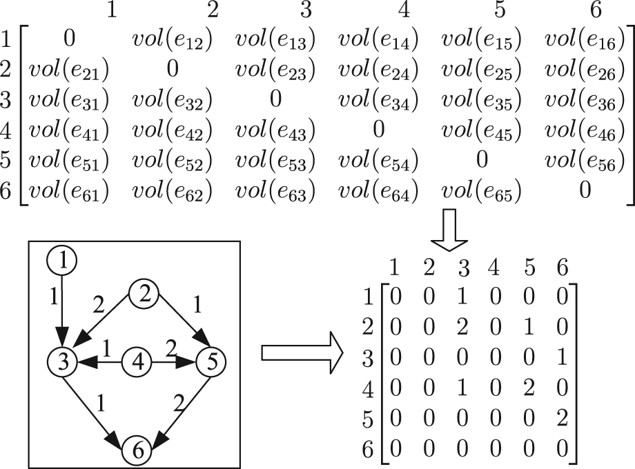
Interconnection matrix of a task graph.
As stated previously, the placement problem is equivalent to determine the assignment of the node ID to the cell ID. This assignment can be mathematically represented by an
According to the one-to-one correspondence between the cell ID and the cell coordinate, the minimal links between two cells are calculated by the cell coordinates in case no faulty cell exits, as shown in equation (1)
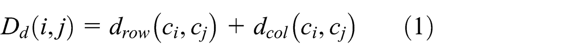
where
Based on the permuted interconnection matrix

In order to ensure the feasibility of routing,


The constraints on the elements of
Formulation of routing
The object of routing is to find a legal set of paths that accomplishes the required interconnections between cells based on the placement. It is clear that small amount of total links obtained in the process of the placement will reduce the degree of routing congestion. A routing matrix satisfying communication bandwidth will be obtained based on a valid result of placement even if it is not the optimal result. Thus, a feasible connection will be accomplished by repeated iterations of a routing algorithm. In order to improve the quality of global wiring, a scheme of ripping up and retrying around congested area is needed.
Our overall routing methodology is a two-phase approach. In phase 1, the path with source cell and destination cell in one line will be routed directly in order to obtain the shortest path. Phase 2 is a routing for long-distance connections. Since the long-distance connections denoted in the permuted interconnection matrix
Implement issues
The process diagram of our approach implementing the placement and routing is shown in Figure 4. First, a genetic algorithm with staged research is applied to find a permutation matrix

Main process diagram of our approach to implement placement and routing.
Genetic algorithm for placement
Equation (2) is in the form of a combinatorial optimization problem. A genetic algorithm is suitable to solve optimization problems. 20 A genetic algorithm is used to explore the design space efficiently for task assignment, mapping, and routing path allocation. 21 The authors used a genetic algorithm to achieve high-quality mapping for NoC. 12 However, due to the constraints of equation (6), we need to select appropriate schemes which fit well in our BQAP formulation.
According to the binary constraints on the elements of permutation matrix
Encoding

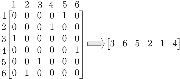
Encoding for a permutation matrix
Crossover
A crossover is to produce a new feasible solution with the good characteristics of parent chromosomes. Since some nodes in the task graph are required to assign to some specific cells in the architecture graph, the chromosomes are divided into substrings for crossover. Then, new chromosomes are constructed by the new substrings. An example of crossover is given below with two substrings, as shown in Figure 6. First,

Crossover of two chromosomes.
Mutation
A mutation operation is performed for each child. Similar to the operation of crossover, a child is divided into substrings. Then, two numbers in a substring randomly selected are swapped to generate a new substring. Then, the new substrings constitute a new child with two numbers swapped. The swapping is valid only if it reduces the number of the total links. After the mutation operation, one of the two children with the minimum links is chosen as the parent 1 for the next evolution.
IACA for routing
There are two types of connections, adjacent connections and long-distance connections, indicated by the permuted interconnection matrix
For the second type of connections, the source cell and the destination cell are neither in the same rows nor in the same columns. Communication bandwidth makes the routing quite difficult. The difficulty in the routing increases as the complexity of the connections grows. Moreover, the connections interact with each other. It is hard to find proper paths for the connections manually or by an exhaust algorithm. Ant colony algorithm can search on several computational threads based on local information and global information on the quality of previously obtained result.22,23 Thus, an IACA is used to realize the long-distance connections. It takes full advantage of prior information about the connections to find a promising solution. For a long-distance connection, the shortest distance between a source cell and a destination cell is fixed in case no faulty cell exits. Thus, the IACA is not used to find a shortest path but to search a suitable path which satisfies communication bandwidth.
Each ant has the coordinate of source cell
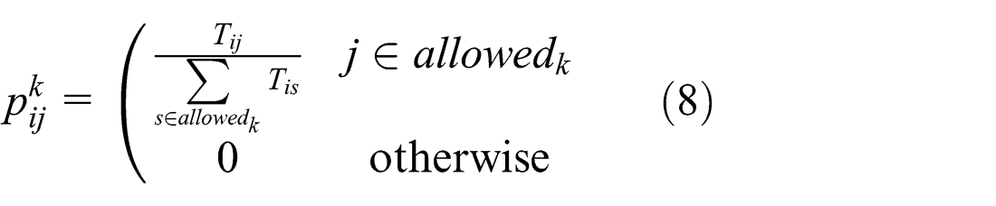
where

where
where
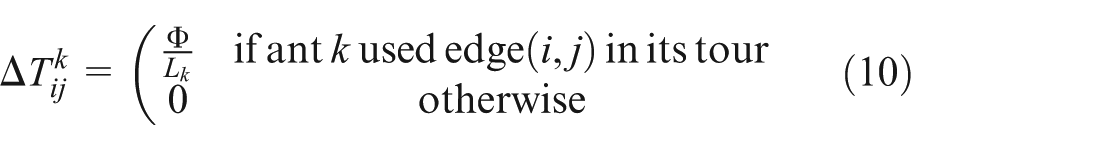
For all long-distance connections, a colony of ants move from the source cells to the destination cells until all ants complete the tour. When all the long-distance connections are routed, a routing matrix is formed. The configurations for Embryonics are developed if

where
A requested routing matrix will be found by repeated iterations of the scheme of ripping up and retrying. In our algorithm, it may need many ants to find valid paths. Most of them find invalid paths and deposit pheromone trails on those paths, which increases the probability to find a valid path by a subsequent ant.
Experimental results
Implementing a Embryonics
multiplier
In order to demonstrate the development of configurations for LUT-based Embryonics, a universal
Figure 7 shows a

Four-input
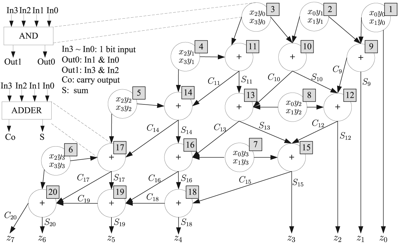
Task graph of a
We construct an Embryonics consisting of a matrix of 5 × 4 cells to implement the multiplier as shown in Figure 9, where 8 cells (in the first row and last row) with a multiplexer to select the input signals realize the AND function and 12 cells (rows 2–4) realize the full adder function. More information about the cell architecture can be found in Zhang et al.
26
Our program of placement and routing was run on MATLAB 7.0 in windows XP OS with dual-core CPU (3.00 GHz). The statistic results of routing are shown in Table 1 by executing IACA in this article and maze-running technique
13
many times. An optimized configuration of a
Summary and comparison of results on routing.

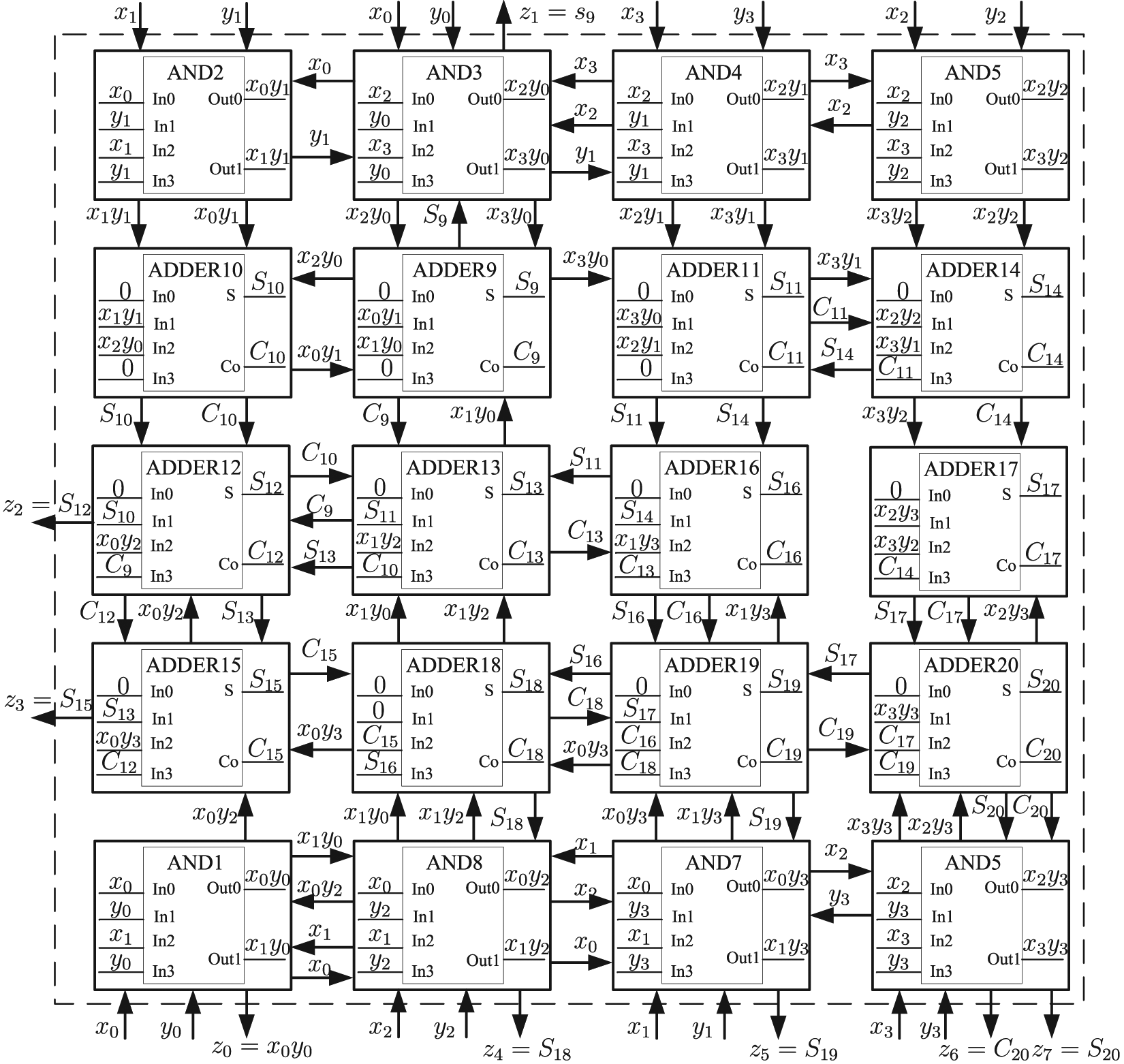
Optimized configuration of a
According to the result of configurations, synthesis and simulation of the
Hardware overhead and supply power.


Implementation of the
Discussion
In some task graphs, the input and output signals of some logic-nodes are more than the communication bandwidth of the cells in architecture graph. In this case, the placement and routing cannot be accomplished. Thus, these logic-nodes should be divided into several sub-nodes where the input and output signals are less than the communication bandwidth of cells.
For a task graph with a large number of logic-nodes, the runtime of placement and routing would increase rapidly. In order to decrease the runtime, a complex task graph is required to be partitioned into several subgraphs. The details about partition approach can be found in Le Beux et al. 27 For a practical application, trade-off between runtime and performance is required in the development of configurations for Embryonics.
Conclusions and future work
This article presents an approach to implement the development of configurations for Embryonics based on graphic mapping. Based on metric embedding technology, the problem of configurations is formulated to BQAP, which can be viewed as a placement and routing problem with constraint of Embryonics architecture. A genetic algorithm with staged research is used to find a placement matrix. Also, an IACA provides a valid routing matrix based on the placement matrix. After this, an optimized configuration for LUT-based Embryonics can be found. A
Footnotes
Academic Editor: Xiaotun Qiu
Declaration of conflicting interests
The authors declare that there is no conflict of interest.
Funding
This work was supported by the National Natural Science Foundation of China (grant no. 51275520).