
Abstract
A framework of multi-objective topology optimization for vehicle powertrain mounting bracket design with consideration of multiple static and dynamic loading conditions is developed in this article. Incorporating into the simplified isotropic material with penalization model, compromise programming method is employed to describe the multi-objective and multi-stiffness topology optimization under static loading conditions, whereas mean eigenvalue formulation is proposed to analyze vibration optimization. To yield well-behaved optimal topologies, minimum member size and draw constraint are settled for meeting manufacturing feasibility requirements. The ultimate mounting bracket is reconstructed based on the optimum results. Numerical analyses of the bracket are performed, followed by physical tests. It is proven that topology optimization methodology is promising and effective for vehicle component design.
Keywords
Introduction
Powertrain mounting bracket is an important design objective for the vehicle systems. Its function is to maintain the position of the engine and transmission relative to the vehicle’s chassis, transmit forces, and torques from the engine to the vehicle’ chassis without failure (strength) and provide sufficient springing and damping to reduce the effects of wheel impacts and vibrations on the engine. In light of its potential impact on the ride and handling performance, demands for higher design requirements with weight reduction to improve cost and fuel efficiency are necessary. Therefore, there is an increasing interest in designing the mounting bracket through powerful and advanced tools for rational and optimum structural design.
Topology optimization has been viewed as one promising methodology.1–3 The aim of the optimization process is to explore competing optimal topologies at initial design stage. Generally, topology optimization in structural design is mainly focused on single-objective optimization problem, such as compliance minimization and frequency maximization. However, there usually exist conflicting multi-objective designs’ criteria that must be considered in practical engineering problems. For example, increasing the stiffness and reducing the weight are both typical design goals for structural design, but these objectives conflict with each other. Recently, a mass of techniques and applications of multi-objective topology optimization have been seen both in the vehicle design and in multi-physics field in general. Optimization problems taking into account static and dynamic performance have been demonstrated for a compressor bracket, 4 frame reinforcement, 5 and steel wheel. 6 Optimization algorithms for compliant mechanism considering mutual energy (flexibility) and mean compliance (stiffness) have been reported in Luo et al., 7 and those considering desired displacement and mean compliance in Zhu et al. 8 and Lin et al. 9 Recently, topology optimization with extensions and development is investigated for heat sink device in Koga et al., 10 thermoelastic structures in Deng et al., 11 thermo-mechanical compliant mechanisms in Li et al., 12 and periodic composite material in Liu and Yin. 13
Multi-objective topology optimization formulation
Density-based topology optimization theory
Given a design domain Ω of finite elements, the Young’s modulus of an element is a function of the element design variable xe given by the standard simplified isotropic material with penalization (SIMP) interpolation scheme 14
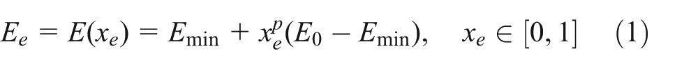
where E0 is the Young’s modulus of solid material, Emin is a very small stiffness of void material in order to avoid singularity of the stiffness matrix, and p is the penalization power to ensure solid-void solutions.
Topology optimization for mounting bracket under static load
According to the principle of virtual displacement, the optimization problem for a linearly elastic structure is minimum compliance (equivalent to maximum stiffness) design while satisfying the volume constraint at the same time. Incorporating into the SIMP model, the mathematical formulation can be specified as
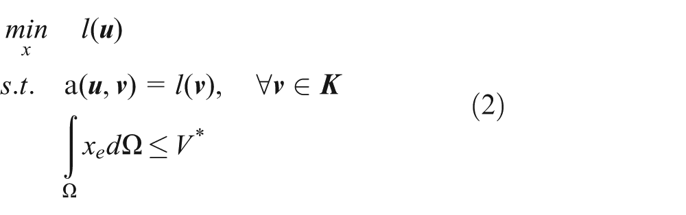
where
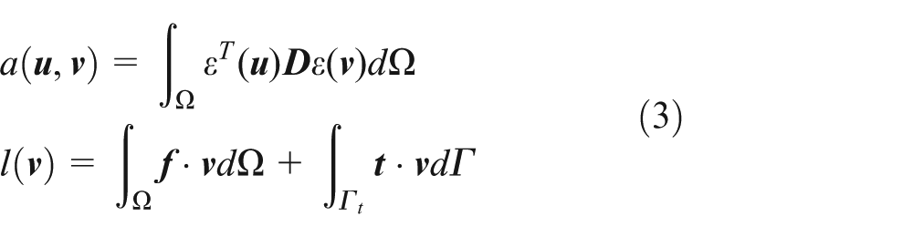
where ε is the strain tensor and
Stiffness design on the bracket structures is an essential part for better vehicle ride and durability characteristics, which is used to pursue a compromised overall stiffness to accommodate various vehicle driving conditions. Unique optimal topologies corresponding to different loading cases generally are not available at the same time. Thus, the topology optimization subject to multiple independent sets of loads can be regarded as multi-objective problems, which are effectively solved by some well-established approaches, such as the weighting method, compromise programming, and evolutionary algorithms. Among the available approaches, compromise programming is viewed as the most suitable candidate due to its conceptual simplicity and ease of implementation.
Compromise programming proposed by Zeleny 15 minimizes the normalized distance between the ideal point and is generally not achievable, and the feasible point. The ideal point specified by the optimum values for individual objective problem is defined as the base point. The efficient set of all feasible non-dominated solutions can be obtained by varying the corresponding weighting factor, which forms Pareto-optimal frontier that no better outcome can be achieved without making at least one objective worse-off. The feasible point with the shortest distance to the ideal point is recognized as the optimum solution.
The mathematical formulation for mean compliance is defined as

where m is the number of loading cases, wk is the weighting factor with wk ≥ 0,
Dynamic topology optimization of mounting bracket
In the vibration problem, optimization problem is formulated by maximizing the natural frequency under the volume constraint. The mathematical formulation through the principle of virtual displacement can be stated as
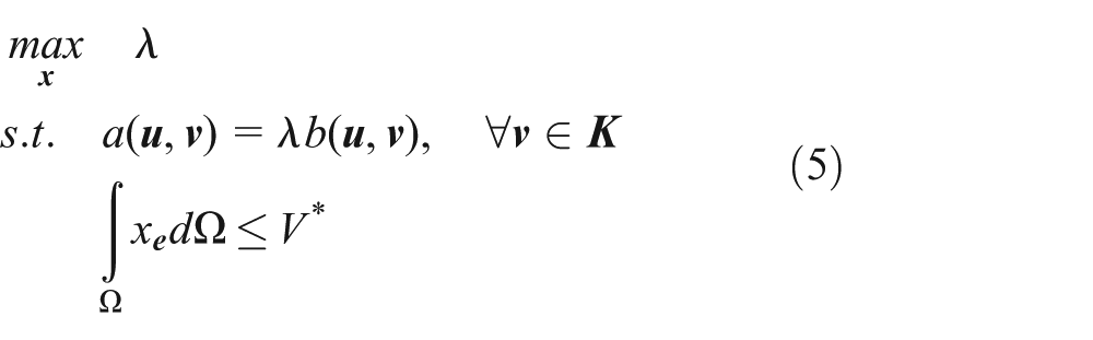
where λ is an eigenvalue for free vibration.

where ρe is the material density associated with each element.
The natural frequency of vibration of the bracket has a major effect on vehicle noise, vibration, harshness (NVH), ride quality, and handling performance, where vibration problems under working conditions might be the kernel issues for the optimization of the bracket. For dynamic topology optimization, when the objective concerns maximization of the kth eigenfrequency, the other eigenfrequencies may fall down to the lower values and switch their orders frequently in the optimization process. In this case, the oscillation of the objective function may occur, and the discontinuous of the sensitivity of the objective function might appear. This may result in divergence of the optimization problem. 16
In order to overcome this problem, the mean eigenvalue Λ combining the multiple eigenvalues is suggested as the objective function

where λi is the chosen eigenvalue, si is a given weighting factor, and λ0 and λ0i are the specified shift parameters. Here, n is the number of eigenvalues associated with the mean eigenvalue.
Multi-objective topology optimization formulation of the bracket
In this section, multi-objective topology optimization with static and dynamic objectives is formulated using compromise programming. The mean compliance and the mean eigenvalue are integrated into the multi-objective function that is to be minimized. The total thus has the form
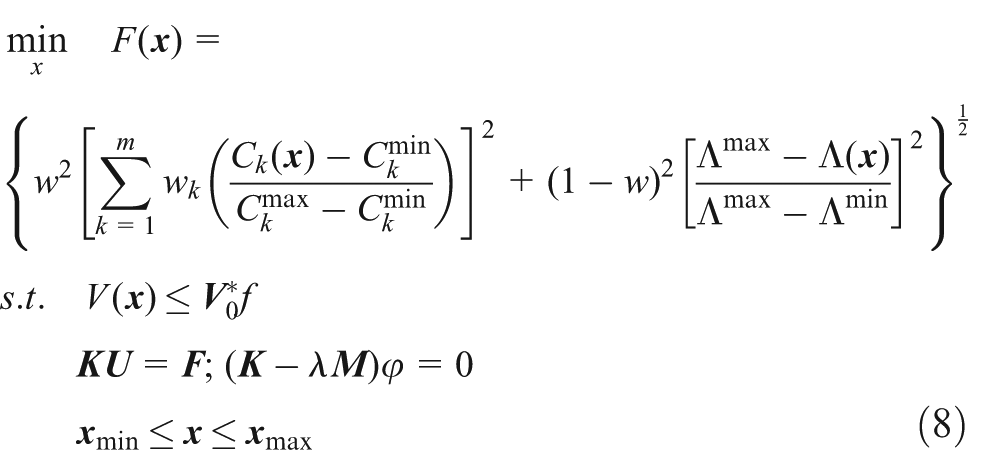
where F(
The implementation of the multi-objective formulation is carried out by making use of user-defined function of commercial software package Optistruct 11.0, which might be one of the best practically used software packages at present to perform structural topology optimization problems. Figure 1 illustrates the flowchart of multi-objective topology optimization procedure.

Multi-objective topology optimization flowchart of the mounting bracket.
Structural multi-objective topology optimization of the bracket
Design space
The design space is the fundamental input for topology optimization. It represents the volume that material can occupy without interfering with any surrounding components. The overall design environment is illustrated in Figure 2. The space is defined by the extreme position of the semi-axis, the transmission housing, the subframe, and the required clearances between the components. The resulting available design space and the corresponding finite element models of the mounting bracket are shown in Figures 3 and 4, respectively. The total three-dimensional (3D) elements and nodes are 17,537 and 21,420, respectively.

Design environment of the mounting bracket.

Design space of the mounting bracket.
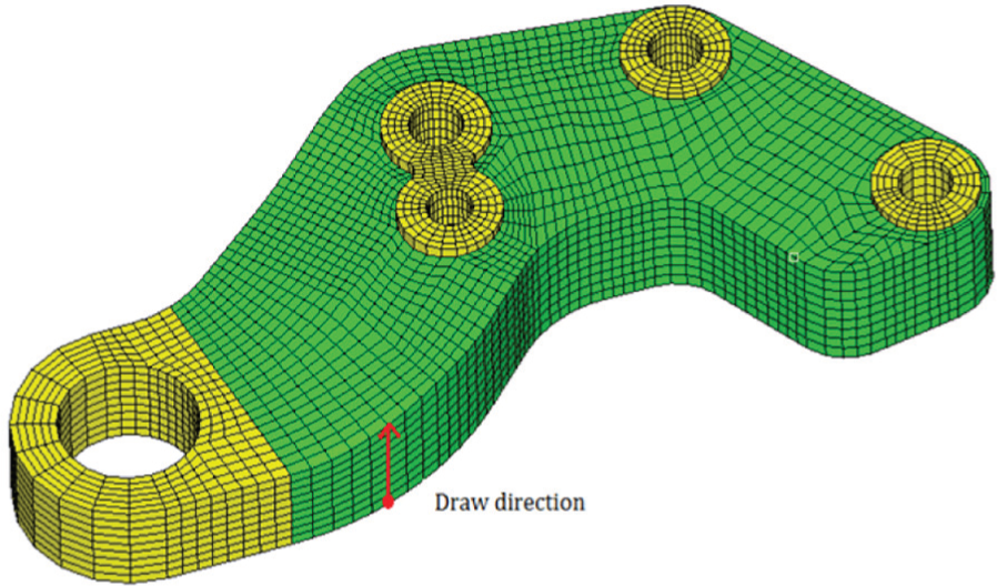
FEM of the mounting bracket.
Boundary conditions
In order to obtain different sets of loading cases under vehicle driving conditions, multi-body dynamic modeling and simulation of the vehicle is developed through the commercial code ADAMS/Car. There are several important factors to be considered when achieving the virtual prototype model that can be summarized as follows:
Layout of powertrain system;
Coordinate of center of mass and inertia parameters of powertrain system;
Output torque of engine and speed ratio of transmission;
Stiffness and damping characteristics of rubber bushing.
Table 1 shows the 15 typical loading cases and the calculated forces at the rubber bushing of the mounting bracket.
Powertrain system loads at mounting bracket.

The connecting bolts are simplified as independent node linking with dependent nodes of the contact internal surfaces of the bracket. Displacement constraints and loads have been applied on the connecting nodes and the central of the rubber bushing connecting the mounting bracket to the subframe, respectively.
Manufacturing constraints
The common numerical instability problems of topology optimization are checkerboards and mesh dependence. Topology optimization without regularization scheme is usually ill-posed. The minimize member size (MMS) is used to yield a well-behaved optimization through suppressing these problems.
For the casted aluminum bracket, draw constraint must be pre-determined in the design space for meeting manufacturing feasibility requirements, which significantly influence the cost, quality, and productivity.
Multi-objective function implementation
The procedures can be briefly summarized as follows: (1) implementing single static and dynamic topology optimization under each loading cases, respectively, to obtain
Optimal results and the optimum topologies
The topology optimization design of mounting bracket is implemented by the commercial software package Altair Optistruct 11.0. A casted aluminum alloy ALSi9Cu3 has been considered with the materia properties: Young’s modulus E = 72,500 MPa, Poisson’s ratio v = 0.33, and density ρ = 2.7 ×10³ kg/m3.
The mean compliance with respect to the 15 static typical loading cases, and the mean eigenvalues associated with first four natural frequencies are considered in the multi-objective function. Applying 50% volume constraint, the results obtained by multi-objective optimization with various weighting factors are summarized in Table 2. The single vibration optimization (w = 0.0) and the single static optimization (w = 1.0) are shown in Figure 5, respectively. The best compromise design is found in the case of w = 0.3 with the best optimal topologies with iterative history shown in Figure 6. The optimization process converged after 78 iterations. The optimized structure of the bracket, which is modeled based on the result of multi-objective topology optimization, is made in CATIA, as shown in Figure 7.
Optimal results summary of the mounting bracket.


Optimal topologies of the mounting bracket: (a) w = 0.0 (single vibration optimization) and (b) w = 1.0 (single static optimization).

The best optimal topology optimization results: (a) the best optimal topologies (w = 0.3) and (b) the objective function iterative history.
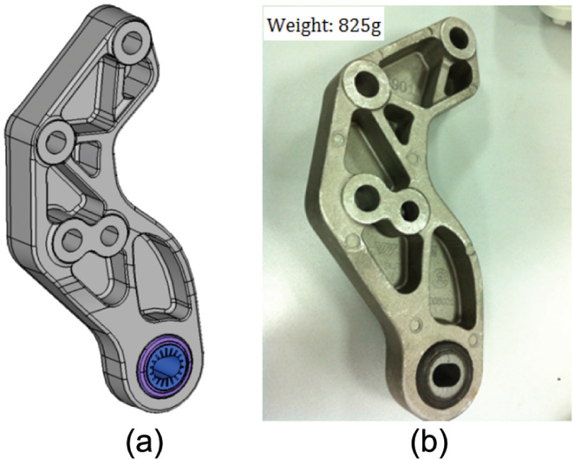
Optimized mounting bracket based on topology optimization result: (a) reconstructed geometrical model and (b) specimen configuration.
Simulation and experimental verification
To check the validity and quality of the optimization methods and results, performance analysis of the mounting bracket including strength and natural frequencies is performed, followed by comparison of physical test including strength test and durability test.
Strength analysis
The calculated von Mises stresses and maximum principle stresses related to the fifth loads case are shown in Table 3. Note that the yielding stress and tensile strength of material ALSi9Cu3 are 120 and 270 MPa, respectively.
Stress results of 15 load cases.

It can be seen from the results listed in Table 3 that the maximum von Mises stress is 106.3 MPa no more than 75% of tensile yield strength (that is, −3σ of yield strength), which occurs at forward rock cycle loading case. The corresponding von Mises stress and maximum principal stress distributions in the mentioned loading case are shown in Figure 8, respectively.

Stress distribution of forward rock cycle loading case: (a) von Mises stress distribution and (b) maximum principal stress distribution.
Modal analysis
The natural frequency and mode shape parameters of the mounting bracket are extracted by modal analysis, which is useful to understand the vibration characteristic of the component. Obtained natural frequencies with the first two mode shapes are shown in Table 4 and Figure 9, respectively.
Natural frequency results.


Simulated mode shapes from modal analysis: (a) first mode shape, (b) second mode shape, (c) third mode shape, and (d) fourth mode shape.
As the results listed in Table 4 show, the first natural frequency occurs at 851 Hz, higher than 600 Hz for NVH requirement. It is also revealed from the results that the first vibration shape swings before and after the direction, the largest deformation occurring in the head of the bracket.
Strength test
Strength test is also performed for the mounting bracket to verify the correctness of the finite element method (FEM) analysis. The strength testing facility assembly with the specimen is shown in Figure 10. The excitation is provided by a hydraulic actuator, which is positioned up the rigid column to which the test specimen is attached. The test detects the failure mode through the force and displacement sensors, and cut off the power source immediately to protect the equipment when the specimen is destroyed.
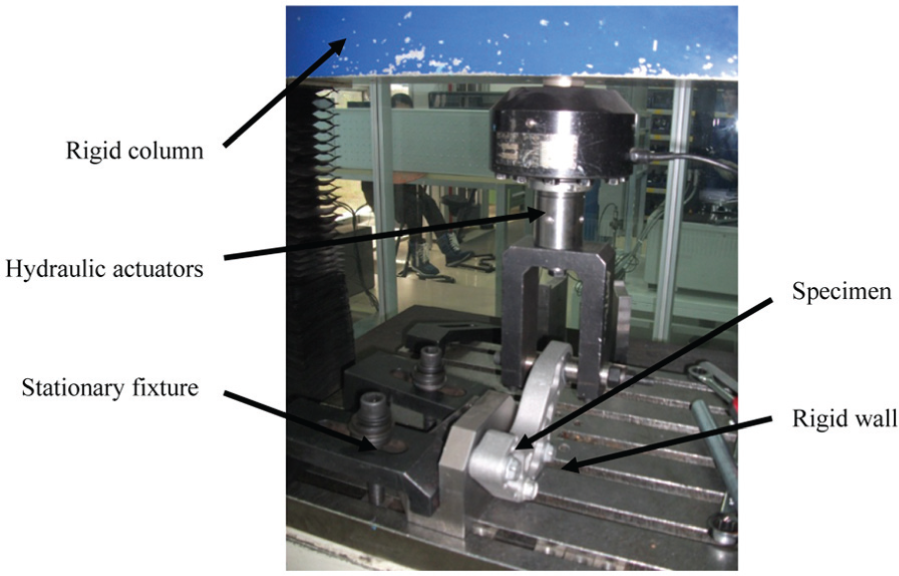
Strength test of mounting bracket.
Three specimens are applied to the X+ and X− direction tests, respectively. The failure load and the corresponding failure mode of the bracket are shown in Table 5 and Figure 11, respectively. Note that for the bracket, the failure load is larger than the target value, and thus, the strength satisfies the requirement, as shown in Table 5. As depicted in Figure 11, the crack position is located at the surrounding bolts. It is demonstrated that the test results and FEM analysis are compatible with one another for the bracket’s strength analysis.
Failure loads of strength test.

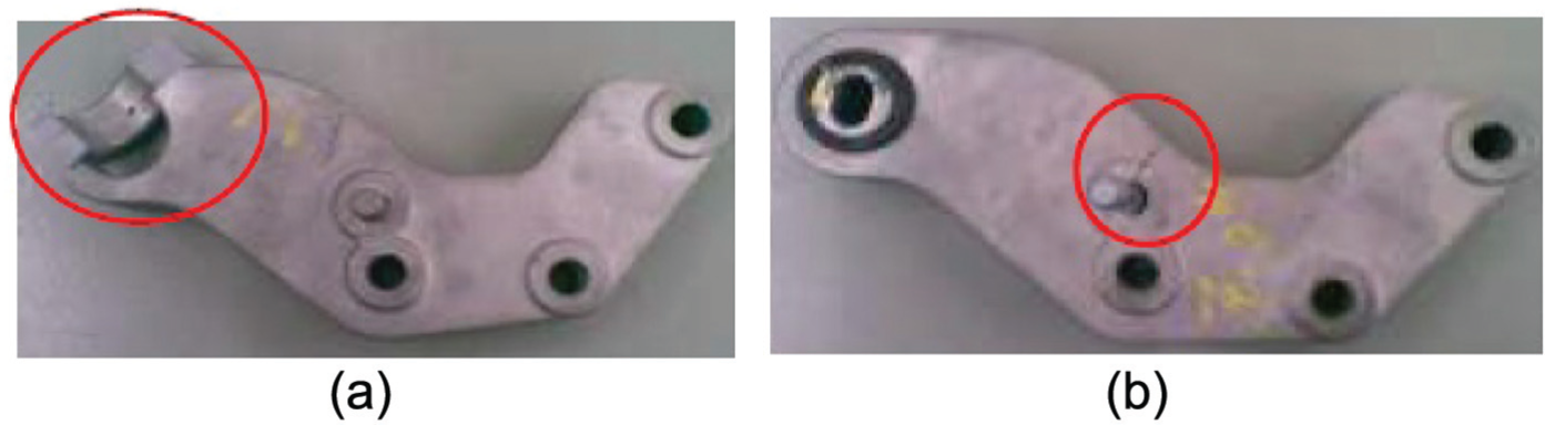
Strength test results: (a) X+ direction failure mode and (b) X− direction failure mode.
Durability test
Durability test is performed on the specimen in tension loading case so as to clarify the fatigue property. A uniaxial servo-hydraulic fatigue test machine with the specimen is shown in Figure 12. Testing is carried out under loading amplitude of 8500 N, with sine wave and frequency of 3–5 Hz.

Durability test of mounting bracket.
The results in Table 6 confirm that the characteristic life of the bracket exceeds than 1,500,000 cycles, more than three times of the target of 500,000 cycles. Therefore, the calculated structural reliability has reached 99% based on the probability theory and mathematical statistics. This indicates that the durability fully satisfies the acceptance criterion.
Durability test results.

Conclusion
The process of structural design for powertrain mounting bracket based on multi-objective topology optimization methodology has been proposed. The theoretical foundation of multi-objective function has been formulated by compromise programming method, where two objectives, mean compliance and mean eigenvalue, are considered in the multiple static and vibration problems, respectively. Multi-objective topology optimization formulation of the mounting bracket is implemented by the commercial software package Altair Optistruct 11.0. Performance characteristics are investigated based on the design obtained from topology optimization through numerical and experimental investigations. Based on the results, the following conclusions are obtained:
Multi-objective topology optimization approach can be well implemented by compromise programming to generate an optimal compromise candidate satisfying both static and vibration performance.
MMS provides interesting well-behaved topologies for topology optimization with manufacturing constraints to effectively suppress numerical instability problems.
The rational ultimate structure can be verified through the followed reasonable numerical analyses and experimental tests, which investigate the validity and quality of the optimization methods and results.
Footnotes
Academic Editor: Seung-Bok Choi
Declaration of conflicting interests
The authors declare that there is no conflict of interests regarding the publication of this article.
Funding
This research was supported by National Natural Science Foundation of China (Grant No. 51275040 and No. 50905017) and the Programme of Introducing Talents of Discipline to Universities (No. B12022).