
Abstract
The objective of the investigation was analysis of the wear of milling cutters made of sintered carbide and of boron nitride. The article presents the life period of the cutting edges and describes industrial conditions of the applicability of tools made of the materials under investigation. Tests have been performed on modern toroidal and ball-end mill cutters. The study has been performed within a production facility in the technology of high speed machining of 55NiCrMoV6 and X153CrMoV12 hardened steel. The analysed cutting speed is a parameter which significantly influences the intensity of heat generated in the cutting zone. Due to the wear characteristics, two areas of applicability of the analysed tools have been distinguished. For vc ≤ 300 m/min, sintered carbide edges are recommended; for vc > 500 m/min, boron nitride edges. For 300 ≤ vc ≤ 500 m/min, a transition area has been observed. It has been proved that the application of sintered carbide edges is not economically justified above certain cutting speed.
Introduction
Each machining process involves various physical phenomena whose intensity depends not only on the machining conditions and parameters, but also on the tool wear degree. Tool wear is a continuous process and influences the machining dynamics. Increase of the cutting speed results in the change of abrasive wear as dominant to chemical wear as the dominant feature. 1 Increase of the width of the wear land on the flank face causes intensive growth of friction forces, which results in the increase of the cutting force. 2 Extreme tribological conditions developing at high tool–chip interface temperatures tend towards the acceleration of tool wear. The tool wear intensity, in addition to its direct influence on the tool life, 3 also influences micro ridges and microhardness of the machined surface.4–8
The tool material most often applied in high speed machining (HSM) of hardened steel is sintered carbide with anti-wear coatings. Intensive investigation and tests of the application of boron nitride – cubic boron nitride (CBN), in industrial conditions are in progress because the use of it is most effective in high cutting speed range due to the occurrence of hot cutting mechanism. As a result of cutting speed growth, the temperature in the cutting zone increases and the machined material is plasticized. 9 In the low cutting speed range, the material remains hard and brittle, which may result in intensive abrasive wear or cracking of the CBN cutting edge. That is why CBN edges can be used for finish machining of hardened steel in the cutting speed range of vc = 300 ÷ 1200 m/min. 8 Sintered carbides are characterized by much lower hardness and lower cutting temperature than boron nitride. However, the common use of them is due to their much lower price, higher ductility and resistance to brittle cracking than those of CBN edges. According to Becze et al., 10 the main mechanism of the wear of CBN and sintered carbide edges is chipping due to the dynamics of the milling process. Edges of sintered carbide with average grain diameter of less than 1 µm have higher hardness and resistance to wear and brittle cracking. In respect of the tool life, application of anti-wear coatings is also important. Although sintered carbides have many advantages, their hardness at high temperature is much less than that of boron nitride. Due to that, it is recommended to machine hardened steels with sintered carbide edges in the cutting speed range of vc = 150 ÷ 450 m/min. 11
Milling under HSM conditions is widely applied in manufacturing of moulds, dies and stamping dies where curved surfaces are often machined. 12 Precision machining of those surfaces is most often performed by means of ball-end mill cutters. 13 At the moment, investigations aiming at improvement of the geometry and design of those cutters to make it possible to obtain better technological effects are in progress. 14 Ball-end mill cutters with negative rake angle, γ 0 = –20° and γ 0 = –45°, have appeared. Their design solution allows better geometrical accuracy of the machined surface to be obtained and better tool life as compared to the conventional ones. A very important factor in the process of milling a curved surface with a ball-end mill cutter is the selection of machining strategy and the machined surface inclination angle, α. 14 Those parameters significantly influence the time of machining, quality of the machined surface, as well as the tool life. 15 According to investigation results,11,16 the machined surface inclination angle, α = 0° should be avoided because in that case, the cutting speed in the tool axis is equal to 0. This can cause high mechanical stresses in the tool point and, consequently, tool wear by chipping. The severe tribological conditions in HSM favour the wear mechanisms reducing dramatically tool life and particular attention must be paid to the prediction of tool wear. 17 Several studies have established the relationship of cutting parameters with tool life and changes in the surface integrity,18–23 but those publications did not mention the problems related to the production areas of applicability of toroidal and ball-end mill sintered carbide and boron nitride milling cutters.
Experimental set-up
The purpose of the investigation was to determine the ranges of permissible cutting speeds, vc , for milling hardened steel with milling cutters of sintered carbides and boron nitride. The material under machining was plates of hardened steel, 55NiCrMoV6, with the hardness of 55 HRC and of X153CrMoV12 steel with the hardness of 60 ± 1 HRC. The characteristics of the milling cutters used in the investigation can be found in Table 1.
Cutting tool specification.

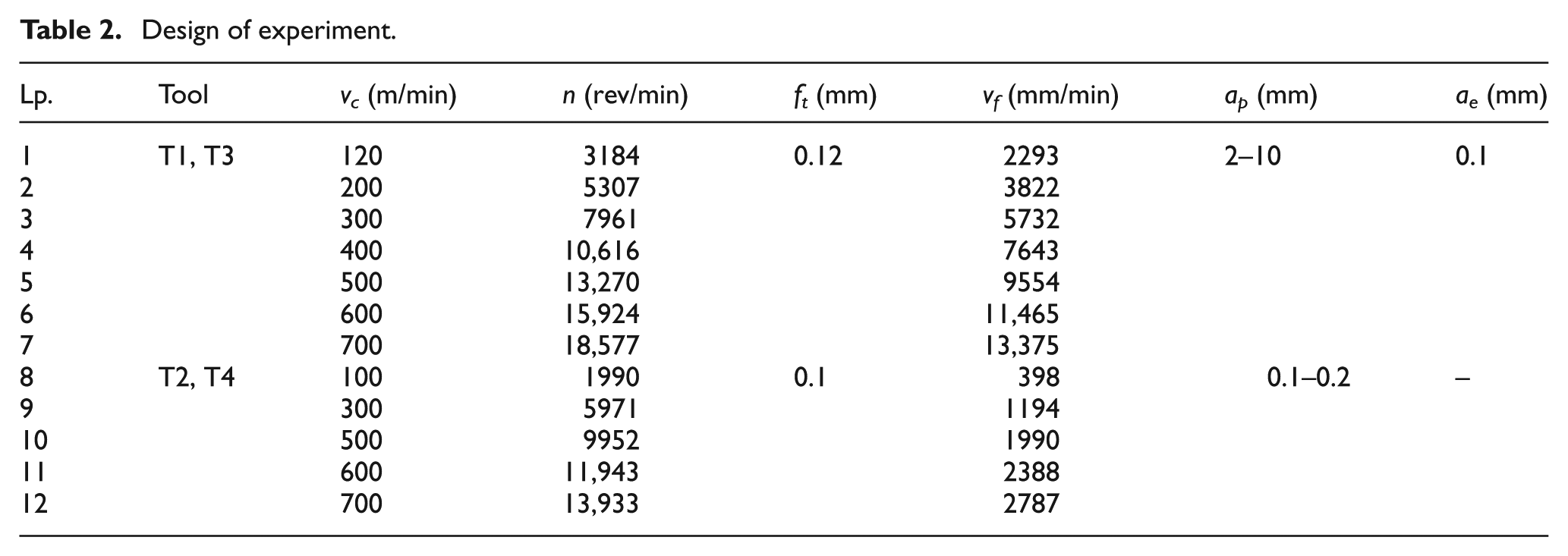
The milling process tests have been performed on a five-axis milling centre made by DECKEL MAHO company, model DMU 60 monoBLOCK. Schematic diagram of the experimental set-up is shown in Figure 1 and the investigation scope has been presented in Table 2.

Schematic diagram of experimental set-up.
Design of experiment.
VBB , average width of flank wear, has been adopted as the indication of the tool wear. A diagram of the measurement can be seen in Figures 2 and 3 for toroidal and ball-end mill cutters, respectively. A workshop microscope with the minimum graduation of 0.01 mm has been used in the measurement.

Method of carbide tool wear measurement for a toroidal milling cutter.

Method of carbide tool wear measurement for (a) ball-end mill cutters of sintered carbides and (b) ball-end mill cutters of boron nitride.
In order to determine the durability of a milling cutter tool point, a criterion of blunting has been defined. In investigation works, geometrical criterion is often applied. This criterion is the most objective one because it describes the tool wear in a direct way. Since the wear was determined by means of the wear index, VBB, VBB < 0.2 mm has been adopted for assessment of blunting. When tools with many edges are investigated, the VBB index value can be considered as the average value of all the edges or as the value of a single edge. In the latter case, the tool is considered blunt when the value of wear of one wedge is exceeded. In this approach, the tool life will always be less than with the adoption of the average value. For this reason, the average value of the VBB index has been adopted in the further part of the present work.
The dependence of the tool life on the cutting speed has been described by a function type
Tool wear experimental investigation
Wear of toroidal milling cutters
The wear processes of the individual edges of tools with many edges are various and very often they show random character. It means that the changes of the wear index as a function of the cutting time of the individual edges are various. Figure 4 shows the changes of the VBB index as a function of the cutting time, ts (separately for each wedge). One can see that the differences of the VBB index values are very large.

Changes of the VBB index as a function of cutting time (the black thick line shows the average value for six edges –‘T1’ cutter).
A characteristic feature of the wear process is that in many cases, one of the edges is worn more rapidly than the others in the initial period (rapid growth of the VBB value of wedge z 1 in Figure 4 for ts = 0.5 min). The most frequent reason is chipping of a fragment of the wedge. As a result, the affected wedge does not participate in the process of milling while the next one, z 2, works with increased geometrical parameters. This, of course, accelerates the wear of wedge z 2 and causes momentary increase of the load of wedge z 3 and so on. That is why the process of a milling cutter wear can be considered in respect of the changes of the individual edges or the average wear value of all the edges. In many cases, the process of a tool wear (changes of the wear indices as a function of the cutting time) can be described by means of a third degree polynomial (Figure 5(a) and (b)). A characteristic feature of the polynomial is that it allows us to distinguish three characteristic ranges, that is, the stage of running-in, stage of stable work and the stage of accelerated wear. However, not every process of wear can be described by this polynomial.

Changes of the VBB index as a function of the cutting time described by means of the third degree polynomial for (a) fz = 0.1 mm/edge and ap = 0.2 mm, (b) fz = 0.08 mm/edge and ap = 0.1 mm (55NiCrMoV6, D = 12 mm, vc = 500 m/min, ae = 0.2 mm –‘T1’ cutter).
When the wear process is very intensive (e.g. for vc = 700 m/min), it is better described by the power function (Figure 6). This is due to the fact that at so high cutting speeds, the wedge durability is very small and the three characteristic ranges cannot be distinguished. Those are cutting speed ranges in which sintered carbide edges quickly reach the blunting limit or become disastrously worn in the course of the process of milling hardened steels. With the growth of cutting speed, the wear process intensity increases regardless of the kind of material being machined. The increase of the wear process intensity results mainly from the increase of the machining process temperature, which can be seen in the photograph of chips in Figure 7. With the increase of vc , the colour of chips changes, which proves that more heat penetrates to the chip and, consequently, the temperature of the machining process is higher.

Changes of the VBB index as a function of the cutting time ts for vc = 700 m/min, fz = 0.08 mm/edge and ap = 0.1 mm (55NiCrMoV6, D = 12 mm, ae = 0.2 mm –‘T1’ cutter).

Chips obtained with various speeds during cutting of material X153CrMoV12: (a) vc = 120 m/min, (b) vc = 400 m/min and (c) vc = 700 m/min.
Wear of ball-end mill cutters
In precise and very precise machining, ball-end mill cutters are used. A ball-end mill cutter is a one for which the condition: rε = d/2 is fulfilled. Furthermore, ball-end mill does not possess a corner, that is, one cannot distinguish the main and the auxiliary cutting edge. Ball-end mill cutters, during milling, should be inclined at a certain angle, α≠ 90° and α≠ 0° (Figure 8).
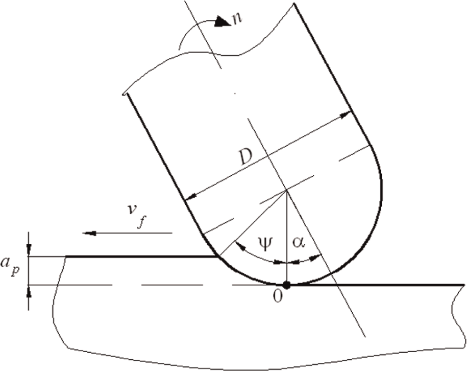
A diagram of a typical process of milling with a ball-end mill cutter with an inclination angle α.
Angle α can be defined as the angle between the axis of the cutter rotation and the direction perpendicular to the vector of the feed motion speed. In practice, α angle is changed by inclining the fixed headstock or the table of the milling machine. Inclination of the milling cutter results in that it does not cut in the rotational axis where the cutting speed vc = 0 m/min.
Figure 9 shows the changes of wear index, VBB , of each of two edges as a function of the cutting time, ts , for two cutting speeds, vc . The least tool wear occurs at the lowest tested cutting speed, vc = 100 m/min. Similarly to toroidal milling cutters, the tool wear grows with the increase of cutting speed, which is a typical relationship in metal machining. At cutting speeds of vc = 100 m/min and vc = 300 m/min, abrasive wear was dominating. At the cutting speed of vc = 500 m/min, after cutting time of ts = 7.1 min, disastrous tool wear by chipping has taken place (VBB > 0.5 mm).

Changes of index VBB as a function of ts for (a) vc = 100 m/min and (b) vc = 300 m/min (the black thick line denotes the average value for two edges –‘T2’ cutter).
Determination of the tool life
Figure 10 shows the tool life determined on the basis of its wear progress at three tested cutting speeds, vc . The value of VBB for two edges has been adopted as the criterion of blunting. At the cutting speeds of vc =100 m/min and vc = 300 m/min, abrasive wear was dominating. In the case of the highest tested cutting speed (vc = 500 m/min), after cutting time of ts = 7.1 min, disastrous tool wear by chipping has taken place. The top value of vc , above which the tool hardness rapidly reduces, depends on many factors, mainly on the kind of the material being machined and the cutting tool material.
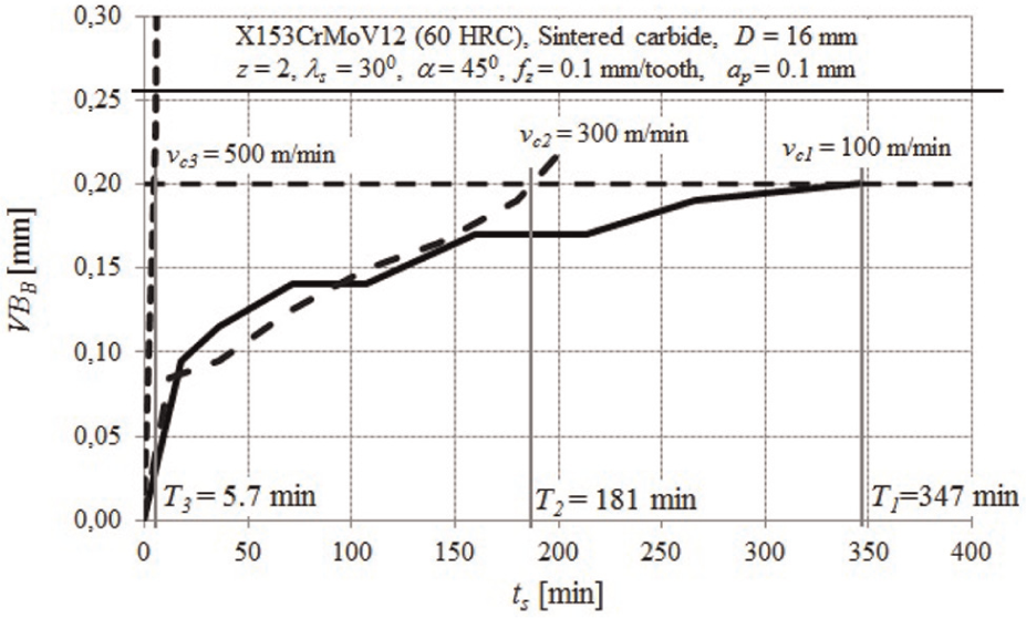
Tool life determined by means of the VBB value (ball-end mill cutter of sintered carbide with TiAlCN coating).
In the dual logarithmic arrangement, the function T = f(vc ) is a straight line. However, in a wide range of cutting speeds, the function T = f(vc ) is slightly different (Figure 11). The function, T = f(vc ), is a straight line only for the vc speed equal to 200, 300 and 400 m/min. For the speeds of 600 and 700 m/min, rapid drop of the tool life takes place, T 1 = 30 min and T 2 = 11 min, respectively.

Tool life, T = f(vc ), in the dual logarithmic arrangement for a toroidal milling cutter.
Similar relationships have been observed for other cutters made of sintered carbide with an anti-wear coating. In hardened tool steel machining, when the cutting speed exceeds certain value (mostly vc > 500 m/min), rapid drop of the tool life takes place. Figures 12 and 13 show the results of a toroidal and ball-end mill cutter tool life. Like in the previous case, a rapid drop of the tool life has been observed starting from a certain cutting speed vc . Toroidal milling cutter life drop occurs from vc ≥ 500 m/min and ball-end mill cutter from vc ≥ 600 m/min. The rapid tool life drop is also proved by the exponent s, which has grown from s = 1.6 to s = 8.6 in the first case (Figure 11) and from s = 1.02 to s = 15.6 in the second case (Figure 13).

T = f(vc ) relationship for a toroidal milling cutter.

T = f(vc ) relationship for a ball-end mill cutter.
This means that the scope of application of sintered carbide edges for precise milling of hardened tool steels is limited. In order to mill under similar conditions with higher speeds, boron nitride edges should be used. In Figures 14 and 15, one can find a comparison of sintered carbide and boron nitride milling cutter tool life at the cutting speed in the range in which rapid life drop does not occur (s = 1 ÷ 2). In both cases, the function curves intersect, which means that up to the moment of intersection (i.e. up to a certain vc speed) it is more advantageous to use sintered carbide edges (longer tool life). After a certain cutting speed is exceeded, boron nitride edges reach longer life.

Tool life comparison of toroidal milling cutters made of sintered carbide and of boron nitride (X153CrMoV12 − 60 ± 1 HRC, D = 12 mm, fz = 0.12 mm/edge, ap = 0.1 mm).

Tool life comparison of ball-end mill cutters made of sintered carbide and of boron nitride (X153CrMoV12 − 60 ± 1 HRC, D = 16 mm, fz = 0.1 mm/edge, ap = 0.1 mm).
In connection with the above, an important practical conclusion can be drawn. Hardened steels should be machined with sintered carbide edges in the cutting speed range of vc < 300 m/min (Figure 16). On the other hand, the best effects of machining with boron nitride edges are obtained when vc > 500 m/min. The width of the transition range (i.e. 300 < vc < 500 m/min) results from the fact that under the conditions of precise machining, the milling parameters can vary in a certain range depending on the kind of tool steel and on the kind and grade of the edges. Consequently, it can be expected that in the transition range, good effects will be obtained in milling with both sintered carbide and boron nitride edges. The selection of the tool material should be determined by the economic reasons in this case.
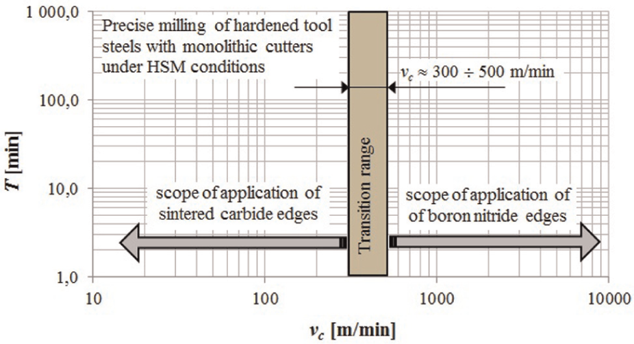
Scope of application of sintered carbide and boron nitride edges in milling under HSM conditions.
As has been observed earlier, it has been proved that in milling hardened steel at lower speeds, sintered carbide edges show longer tool life, but when vc > 500 ÷ 600 m/min the tool life of CBN edges is longer. In almost all cases under investigation, it has been found that with the increase of the cutting speed, the tool life decreases and the length of the cutting path grows (Figure 17).

Influence of cutting speed on the tool life and on the length of the cutting path (X153CrMoV12 − 60 ± 1 HRC).
Conclusion
When machining under HSM conditions, one should always be prepared for a drop of the tool life, but, at the same time, the output increases as the process productivity grows. Additionally, the cost of milling machine exploitation is reduced because the time of machining is shorter. Based on the results described in this article, several important issues regarding the comparison of five-axis HSM milling have been reported:
The process of wear of the tested multi-wedge tools is a random one and progresses with different intensities for each edge. For a definite criterion of bluntness, the wear of individual edges should be assessed or the average value of wear should be considered.
The maximum speed of cutting hardened steels with edges of fine grained sintered carbide (with an anti-wear coating) is vc = 500 m/min. In precise machining conditions, above this speed disastrous tool wear takes place.
In the process of machining hardened tool steel, milling cutters with edges of boron nitride should be used for the cutting speed of over vc > 500 m/min.
In the case of ball-end mill cutters, increasing the cutting speed from 100 to 300 m/min results in the tool life reduction by about 35%, which is a result of disastrous wear.
Footnotes
Appendix 1
Academic Editor: Noël Brunetière
Declaration of conflicting interests
The authors declare that there is no conflict of interest.
Funding
This research received no specific grant from any funding agency in the public, commercial or not-for-profit sectors.