
Abstract
The modeling of milling forces is a crucial issue to understand milling processes. In the literature, many force models and experiments to identify force coefficients are found. The objective of this article is to develop a new approach, based on the traditional average force method, able to measure and compute the cutting coefficients for end mills used in plunging operations. This model has been used to evaluate the effect of the radial engagement on the cutting coefficients themselves, proposing a new strategy to update these values for different cutting parameters. This dependency of the cutting coefficient is particularly important for the determination of the stability lobe diagrams, used to predict the chatter conditions. In this article, the method to assess the cutting coefficients, the results of the experimental tests, and the effect of condition-dependent cutting coefficients on process stability are presented.
Introduction
The milling processes are continuously increasing their market penetration due to arising request of product with high surface finish and dimensional accuracy, such as the die or mold for the housewares and automotive sectors and for the products for the medial and aerospace industries. The widespread application for this technology is sometimes constrained by challenging cases that could suffer from excessive cutter deflection of chatter, which could appear when the cutting parameters are stressed to increase the process productivity. Among the arising machining processes, particular interest is played by plunge milling because it allows to work deep pocket or other difficult-to-access features maintaining a good productivity and accuracy also with slender tools. The advantage of the plunging operation is that the cutting forces are more oriented along the axis of the tool, where the tool proves its highest stiffness.
The first step to model a machining process is the definition of a cutting force model. An analysis of the literature shows that there exist mainly three cutting force models: lumped mechanism model, dual mechanism model, and ternary mechanism model. In the lumped mechanism model, the effect of both the shearing and friction at the cutting edge are described with a single coefficient. This is a simple model that produces reasonably good results with the advantage of its fast implementation in an industrial context. This approach has been developed for flat-end mill and ball-end mill by many researchers; among these, it could be reported by Kline et al., 1 Altintas and Spence, 2 Lazoglu, 3 who extended this concept to the prediction of cutting forces to ball-end mill. Later, more complex models have been developed, taking into account different coefficients for both the shearing and friction contributions at the cutting edge, these are usually called dual mechanics approaches. In particular, Budak et al. 4 developed a general approach that could feed the model with data extracted from orthogonal cutting tests. Then, Altintas and Lee,5,6 Yucesan and Altintas, 7 and Engin and Altintas 8 presented general models that could be used for the reliable prediction of cutting forces for a general end mill, often used to obtain stability lobe diagram (SLD) with zero-order approximation. The last is still the basis for more recent models that include other features such as the introduction of the effect of the runout. 9 A detailed comparison of the most actual approaches to model the cutting force has been carried out by Wan and Zhang, 10 which include also different solutions to carry out one of the most crucial steps in force modeling, the calibration of the model. Some authors, such as Imani et al., 11 also studied the influence of different process parameters such as the axial depth on the cutting coefficients. At the end, the ternary mechanism model 12 identifies and models the contributions of flank shearing, flank rubbing, and bottom cutting effects; the coefficients could be calculated considering together chip load, chip width, and bottom contact width.
It must be reported that although the analytical methods are still the most used approaches to determine the cutting forces, due to the ever-increasing computing capabilities of modern workstations and the availability on the market of commercial software able to simulate the cutting process using finite element (FE) approach, some researchers13–15 used simulation to predict the cutting force. Another interesting and arising approach, able to provide a faster result than FE modeling, is provided by the use of slip line field. 16 This approach is based on the strain, strain rate, and temperature-dependent flow stress of the material and friction coefficient.
It is important to note that the cutting force models are dependent on the tool geometry and the machining process approach, so the choice or definition of optimal cutting model could not be a trivial task. To solve this issue, approaches that are oriented to have a unified model for cutting 17 based on a complete description of tool geometry or to create specific cutting models for each operation are arising. Some examples of this trend are the development of a model specific for the threading operation 18 and the development of a mathematical method to geometrically define a general tool as a flat tool with geometry variables or cutting inserts 19 or alternatively a multi-purpose tool. 20
As stated before, plunge milling is an arising operation because it shows a relatively higher stiffness of the tool in the axial direction, and a larger component of the cutting forces is oriented along the tool axis. As a result, a tool used in plunge milling operation is more stable than the same used in flank milling operation, using the same engagement and cutting parameter values; for this reason, plunge milling has become an interesting strategy because it can often allow higher removal rate than other cutting strategies. Most of the cutting models are specific for the flanking and slotting operations: only few authors investigated the mechanics of plunge milling. 21 Plunge milling is similar to boring (with interrupted cuts), 22 so a different method to measure the cutting force coefficients must be developed. This article proposes a new simple method to obtain experimentally the cutting coefficients for traditional end mills; the idea is to obtain cutting coefficients in a faster way that could be used reliably to feed a plunging chatter model in order to improve the industrial usability of such approach. The chatter model that will be used is the one proposed by Altintas and Ko 21 for plunging.
The proposed method is based on the average force method that is normally used for slotting and flank milling; starting from this background, new relations have been developed to determine the average chip thickness and average coefficients in end mills plunging tasks. Those relationships are used to predict the cutting forces, thanks to a model for the interaction between the material and the main rake angle (in plunge, it is the frontal one, not the peripheral one). Since the developed approach proposes a simple strategy to obtain the coefficients, it is possible to replicate the tests in order to evaluate the effect of the cutting parameters, such as the radial engagement, on their values. Some example of the experimental tests will be provided in this article.
Average force method
Average force model description
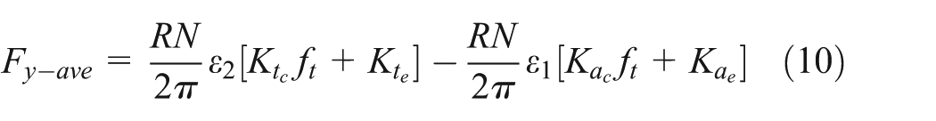
The model developed is based on average cutting force model developed by Altintas and Ko, 21 where the cutting forces are proportional to feed per tooth and to chip thickness. The average cutting force model is one of the most adopted models, thanks to its simplicity and the good accuracy of prediction. However, it must be reported that there are also more complex models that consider nonlinear relationship between force and feed per tooth, 23 obtaining more precise results. The choice of the average cutting force model has been motivated by the larger diffusion; however, the developed geometrical relations could be used also for more complex models. The average cutting force model uses the following description for the cutting forces

where
Plunge average force model
The developed model starts taking into account the geometric position of a tool engaging a workpiece and from the cutting force model. Figure 1(a) and (b) describes a generic configuration of the tool and workpiece with respect to a Cartesian reference system placed with Z-axis coincident with tool axis. The red segment

(a) Generic relative tool–workpiece position cutting a vertical wall. The center of the reference system is coincident with the tool axis, while axis direction is coincident to an external fixed coordinate system, for example, machine system. (b) Top view of a tool–workpiece position cutting a vertical wall.
The angles

Consequently, it is possible to indicate the length of segment

where

With equation (4), it is possible to write in discrete form in the Cartesian reference system the forces at the tooltip


Applying the definition of average forces

And by substituting the analytical form of equation (3) in equations (5)–(7), knowing that this integral is nonzero only between the angles


where N is the number of the flutes and ε variables are expressed by the following formulas


Computation of the force coefficient
To compute the force coefficients, a series of plunge tests must be executed with different cutting parameters: these must be chosen in order to achieve a stable cutting. For each test, the three components of the forces must be measured, normally with a dynamometric table. The tests must be carried out with different values of the feed per tooth. According to the model, the forces are proportional to feed per tooth, so if a linear increment of feed per tooth is chosen, the forces (and their average values) must also follow this trend. For these measures, there is no need of compensating the dynamics of the dynamometric table 28 because it does not affect the average values of the measured forces.
As shown in Figure 2, the average values of the forces are plotted using the feed per tooth as variable. A regressive model could then be used to compute the six cutting force coefficients, using equations (9)–(11).

Example of measurement and data interpolation to obtain force coefficient.
Experimental setup
In order to verify the effectiveness of the proposed model, a set of experimental tests has been carried out. The test piece consists of a rectangular piece of aluminum clamped with a couple of screws to a dynamometric table (Figure 3). Additionally, a microphone was used to verify the stability of the process.29–31

(a) Example of setup with a steel workpiece on dynamometer and (b) detailed view of plunge tests on aluminium block.
The chosen tool was a Mitsubishi Carbide Mill I MX1n 2S3A 12010 ET2020 12 that has 12 mm of diameter and three flutes, the shank was a Mitsubishi EF i MX12—U12N017L080C, the tool holder was a Big Mega New Baby Chuck MGN13 Daishowa Seiki Co. Ltd, and the milling machine was a Mori Seiki NMV 1500. It has been chosen to use a spindle speed of 8000 r/min and to maintain it constant in every test to avoid the problem of coefficient changes with cutting speed. 32 It has also been chosen to perform the coefficient measurements for four different radial depths of cut: 0.5, 1, 2, and 3 mm. For each radial depth of cut, a set of five different feeds per tooth have been tested: from 0.03 to 0.07 mm/tooth spaced by 0.01 mm/tooth.
Results and discussions
The results in terms of average forces and force coefficients are presented in Table 1. Every test was checked to ensure the stability of all of them, with no chatter evidence not on the surface not in signal analysis. The first result is that the average force method provides a good approximation of the mean cutting force, as proven by the very good accuracy of the linear regression model used to interpolate the experimental data. In this case, the behavior of the cutting force could be considered linear, with respect to the chip area.
Force coefficient values.

The tests carried out highlighted also another trend in the cutting force data: the cutting force coefficients change for different radial engagements. This trend is reported in Figure 4(a) and (b), where the nonlinear behavior of the coefficients is evident.
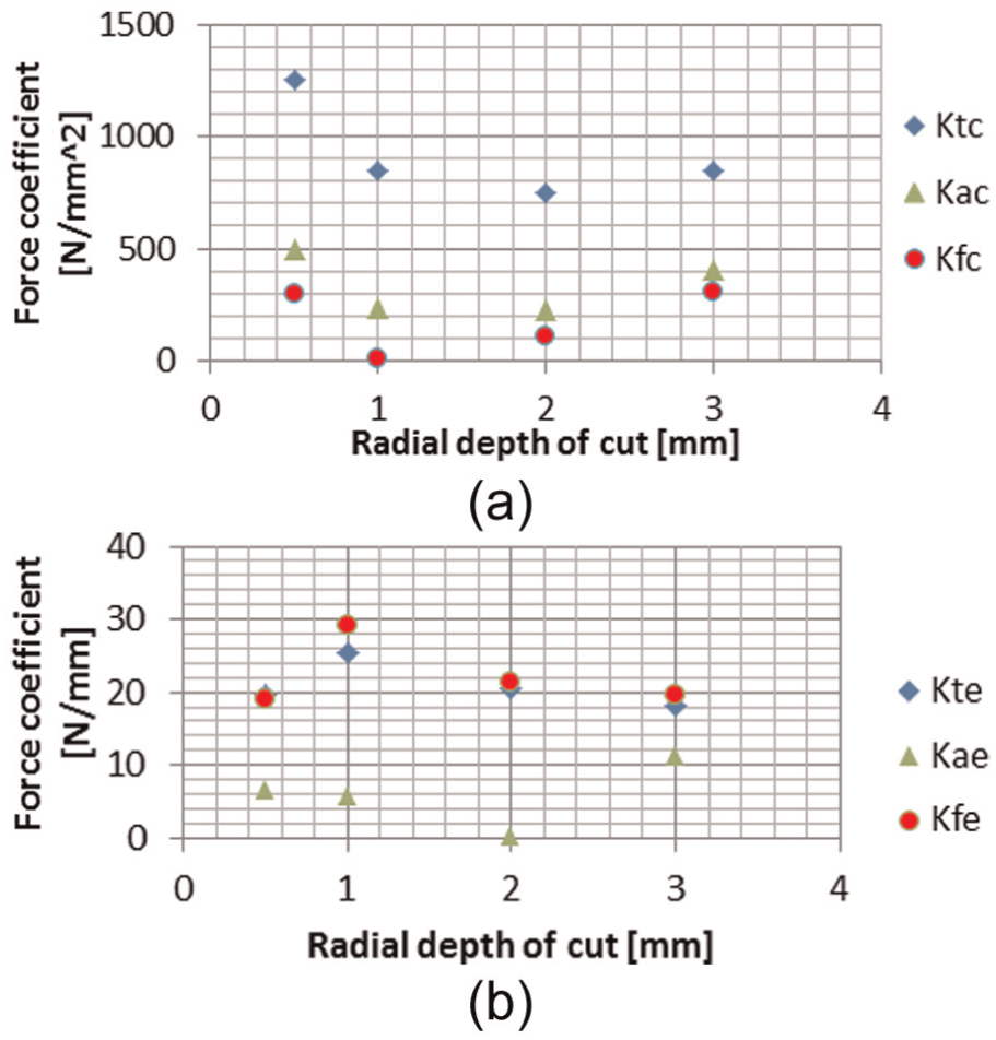
(a) Trend of cutting coefficients and (b) trend of edge coefficients.
It is possible to note that for reduced radial engagement, the cutting coefficient becomes higher when the dimension of radial depth of cut is small; this is probably due to the influence of the corner radius of the cutter. 33 It is possible to confirm that forces are proportional to feed per tooth, but the value of the constant changes with the cutting parameter. In this case, the cutting coefficients show a minimum value for radial depth of cut within the range of 1–2 mm. Edge coefficients are usually relevant on the computation of the cutting forces only in case of low feed per tooth; when using greater feed per tooth, their contribution to the total cutting force is reduced. However, these coefficients do not have a trend as relevant as the cutting coefficients. The values of force coefficient have been used in a kinematic simulation of the cut to test their capacity of describing and foresee the cutting force. Here is reported as an example one of the results obtained for spindle speed of 8000 r/min, feed of 960 mm/min, and radial immersion of 3 mm (Figure 5).
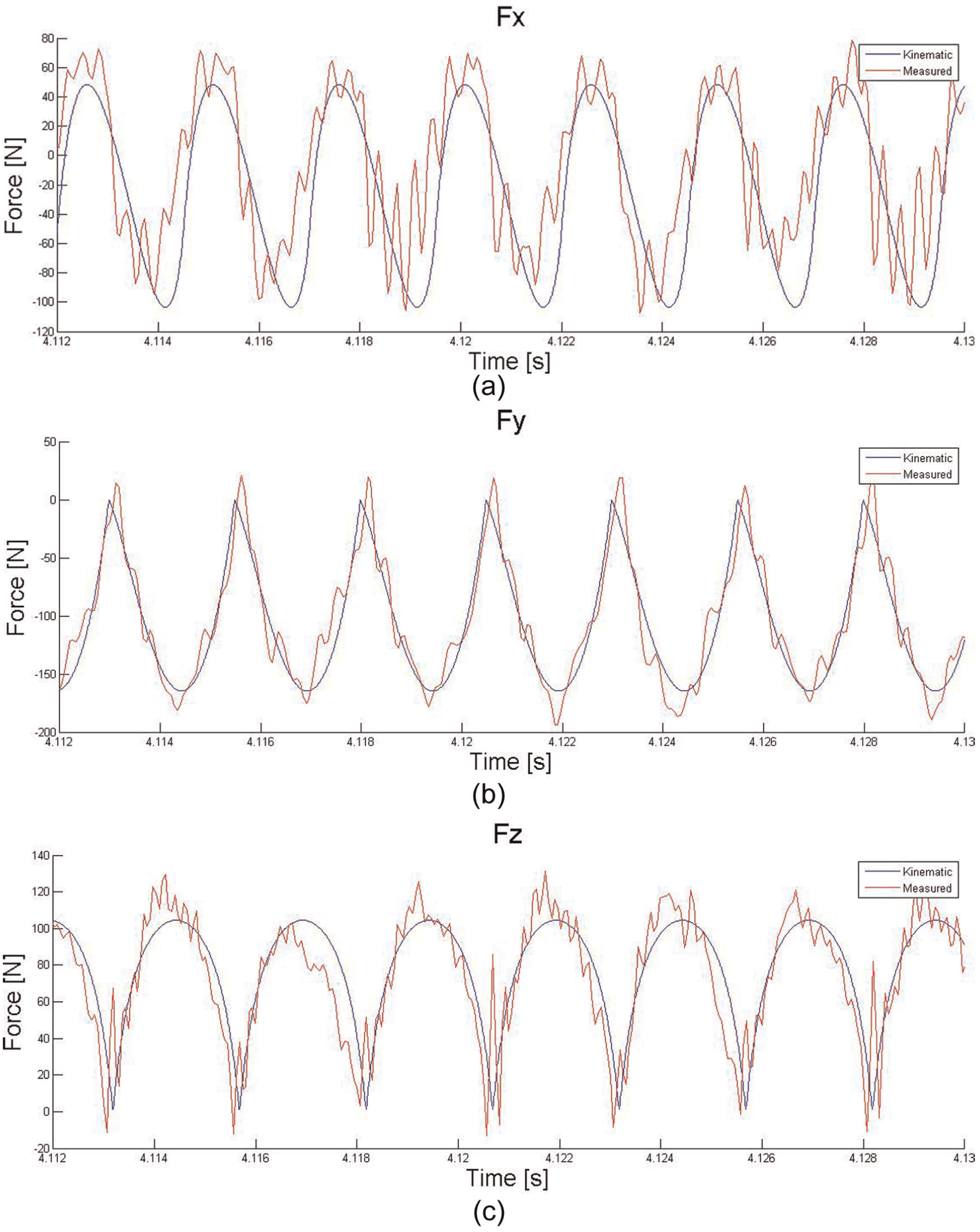
(a) Comparison between kinematic X forces (blue) and measured X forces (red), (b) comparison between kinematic Y forces (blue) and measured Y forces (red), and (c) comparison between kinematic Z forces (blue) and measured Z forces (red).
This comparison have been carried out just using a kinematic model, that it is not able to consider the dynamics of the system, responsible for the high frequency variation of the measured forces. However, the general trend of the cutting forces is correctly represented by the proposed model.
Effect of variable cutting coefficients on SLD
The importance to have a reliable cutting force coefficient lays in the possibility to predict correctly the cutting forces, possibility that could be used to design the fixture and the tooling, and to have a reliable estimation of the stability of the process. Using an analytical solution to forecast the arising of chatter, 21 it is possible to create a SLD to represent graphically the stable and unstable zones. Using the radial engagement–dependent cutting force coefficients, it is possible to evaluate how this parameter affects the stability of the process. In order to solve this system, it is necessary to use an iterative approach: for each cutting speed, a first guess of threshold radial depth of cut is provided and then the value of the cutting force coefficients is updated till the convergence of the result. In Figure 6, the SLD of a plunging operation is reported, as obtained with model in Altintas and Ko 21 with three different radial engagements in which it is possible to see the difference in taking constant cutting coefficients referred to a standard group of coefficient measured at 2 mm of radial depth of cut (blue line in Figure 6).

Continuous lines: SLD with measured coefficients; dashed lines: SLD computed with 2 mm coefficients taken as a constant standard.
Observing Figure 6, it's easy to understand how to predict stability limits obtained with the standard approach (without taking into account the variation of cutting coefficients with radial engagement) leads to errors that can be relevant.
To assess the better accuracy provided by the model-proposed coefficients, some experimental tests of chatter detection have been carried. The stability of the operation has been verified, thanks to the use of different sensors: dynamometer, accelerometers, and a microphone.29–31 The results are reported in Figure 7.

Comparison between SLD with constant coefficient and variable coefficients.
From the data in Figure 7, it is possible to evaluate how the use of the model-proposed coefficients improves the predictive capability of the SLD because it takes into account how the forces are affecting the model at different radial engagements.
Conclusion
In this article, a novel method to compute cutting coefficients has been shown. The average force model and method was applied to plunge milling operations. The obtained coefficients have been used in a kinematic model to have a comparison between predicted and measured forces: this analysis has demonstrated that this method can really be used for force prediction, and the data show a good accord with the measured ones even if the kinematic model does not consider the dynamics of the system. The influence of the radial depth of cut in the determination of the value of the cutting coefficients has also been shown. This trend of the force coefficients shows the possibility to choose a set of parameters to minimize tooltip forces. The variation of cutting coefficient must also be taken into account for the development and for the correct use of analytical plunge chatter models to obtain an accurate SLD.
Footnotes
Appendix 1
Acknowledgements
The authors wish to thank the Machine Tool Technology Research Foundation (MTTRF) and their supporting partners, Mori Seiki and Esprit, for providing the machine tool for the tests and for the general support of their research activities.
Academic Editor: Hyung Hee Cho
Declaration of conflicting interests
The authors declare that there is no conflict of interest.
Funding
This work was carried out within project “ATENE,” funded by Tuscany Region by Operative Programme on “Regional Competitiveness and Occupation” 2007–2013, economically cofounded by FESR.