
Abstract
The response of dispersed droplets to oblique shock waves in the supersonic mixing layer was investigated using the large eddy simulation coupled with the particle Lagrangian tracking model. The generated disturbances based on the most-unstable wave model were imposed to excite the development of supersonic shear layer. The oblique shock wave was numerically introduced in the flow field. Small- and medium-sized droplets remained their preferential distribution in the vortices after crossing the shock wave, while large-sized droplet became more dispersed. The influence of shock waves on the momentum and heat transfers from surrounding gas to droplets was analyzed by tracking droplets’ motion paths. Small-sized droplets responded easily to the shock wave. Compared with the aerodynamic response, the thermal response of droplets was slower, especially under the impaction of the shock wave. The present research conclusions are conductive to analyze the mixing of air and fuel droplets and of important academic value for further understanding the two-phase dynamics in combustors of scramjet.
Keywords
Introduction
Turbulent dispersion of droplets occurs in a number of engineering applications such as energy conversion and propulsion devices. It is required to predict the turbulent transport of evaporating droplets precisely for the designing and operating process. As known, scramjet is an efficient propulsion device for the high-speed vehicle. Shock waves formed inside the scramjet combustor could affect the atomization and segregation of fuel droplets. The characteristics of evaporation and distribution of fuel droplets in supersonic flows influence the further process of combustion severely. The underlying physics governing these processes has not been well understood. Fundamental studies of the droplet-laden supersonic mixing layer and the response behavior of droplets to the incident shock (IS) waves have a significant role in promoting the further development of scramjet.
Mixing layer is a simple but fundamental model for the analysis of turbulent flows inside the combustor of scramjet. Interaction between mixing zones and shock waves has attracted interests in the non-premixed supersonic combustion. 1 Recently, the compressible mixing layer has been studied by the experiments and numerical simulations, which have shown that the growth rate of mixing layer thickness is determined by the evolution of vortices2,3 and is decreased with an increasing convective Mach number.4–9 In addition, turbulence intensity and Reynolds stress are also depressed due to the compressibility effects.5,6 Therefore, the mixing enhancement is more problematic in supersonic flows with high convective Mach number and has attracted much attention. 1 The physics of passive scalar mixing in supersonic turbulent shear layers has been studied. 10 Clemens and Mungal 7 and Clemens and Paul 11 have found that the scalar mixing is also inhibited, which reduces the magnitude of mixture fraction fluctuation in their experimental measurements. Both the mixture fraction probability density functions and the shape of turbulent structures are changed in supersonic flows with high convective Mach numbers.
Most of the numerical simulations study the temporally evolving mixing layer and show the consistent research conclusions on the reduced level of scalar mixing.12–19 The temporally evolving mixing layer usually applies the periodic boundary condition to mimic the development of turbulence and could display the main characteristic of turbulence. However, it restricts the numerical research in a narrow flow region with periodicity and such an approximation is not practical, for example, in the case of an interaction between a free shear flow and shock waves. Hence, it is necessary to perform numerical studies through the simulation of spatially evolving mixing layer flows.15,20–25
Research of the transportation characteristics of particles/droplets in turbulent flows has shown that the Stokes number is a criterion for describing the particle preferential distribution phenomena.26–30 Chung and Troutt 27 numerical simulated gas–solid two-phase flows and indicated that particles have the best spreading ability when the Stokes number equaled unity. Tang et al. 28 found that the flow had largest influence on the dispersion process of particles when Stokes number came to unity and particles distributed the thin layer outside large-scale vortices. As for most of scramjets using liquid fuel, understanding the dispersion of atomized fuel droplets and their exchange of momentum and heat with surround supersonic fluid is particularly crucial for the design of scramjet combustor, since an inability to achieve efficient fuel–air mixing in this engine will directly impact its viability. Wu et al. 31 carried out research in supersonic two-phase flows using large eddy simulation (LES), indicating the characteristics of droplet dispersions in vortices of mixing layers. Ren et al. 32 studied the dispersion of fuel droplets in the supersonic flow and the exchange of momentum and heat between droplets and gas. They found that the smaller the diameters of droplet were, the more intense momentum and heat exchange were done with the gas phase, which could be used to interpret that well mixing would make the combustion of the fuel droplet more sufficient.33,34 However, the investigation of droplet dispersion in high-speed mixing layers and, especially, their responses to shock waves are quite insufficient.
This article documents and discusses the results of on the droplet dispersions in the supersonic mixing layer impinged by an oblique shock wave. The simulation parameters, the governing equations, the sub-grid models, and the numerical method are first detailed. Then dispersions of droplets with different diameters (i.e. particle Stokes numbers) in shocked mixing layers are described. The response of droplet to the shock wave and particle-phase statistics are finally presented and discussed.
Governing equations and numerical methods
Gas-phase equations
The unsteady compressible Navier–Stokes equations are solved in this work. In this research, the volume fraction of droplets is low enough to neglect the influence of droplets on the carries gas. Hence, the governing equations do not contain the source terms representing the interactions between the gas and fuel droplets. The mass, momentum, total energy, without body force, and external heat source, are written in the Cartesian coordinate system as follows


The ideal gas equation of state is used to close the above equations

In these equations, the velocity vector is expressed by ui
, where i = 1, 2, 3. ρ represents the local gas density and P is the pressure. T is the gas temperature and R is the gas constant. Besides, E is the total energy, containing kinetic and internal energies.

and
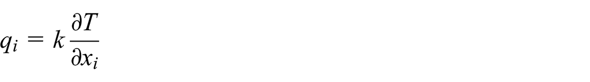
The viscosity coefficient µ and the thermal conductivity
The LES governing equations have been obtained by application of a spatial filter onto the Navier–Stokes equations, separating the larger, geometry-dependent scales of motion from the universal small scales. In this study, the Smagorinsky sub-grid-scale model is applied to simulate the sub-grid-scale behaviors, which are mimicked by the high-order shock-capturing methodology associated with numerical dissipation. The sub-grid-scale viscosity, denoted with the sgs subscript, is written as
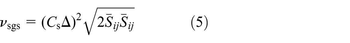
where
Lagrangian particle trajectory model
The point-particle approach is employed in the simulation, and hence, a droplet is treated as a point mass. Since the diameter of a droplet is small and its density of droplets is far greater than that of gas, only the drag force is considered in the present simulation. Hence, the governing equations for the Lagrangian trajectory model read as
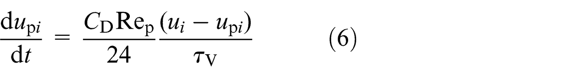

Rep is the particle Reynolds number,


where
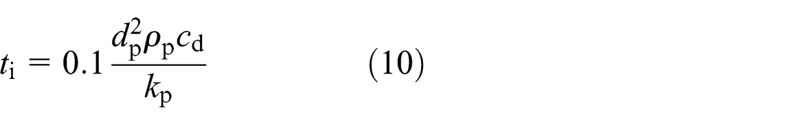
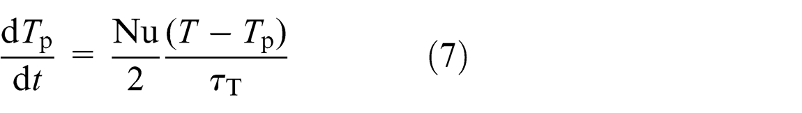
Comparing this time scale with thermal response time, one obtains

In this article, the droplets are kerosene, whose coefficient of heat conductivity is much larger than that of gas. Therefore,
Numerical methods
A finite difference methodology is used to solve the above governing equations. An explicit Runge–Kutta time-integration methodology is applied, obtaining a third-order time-accurate computation. For example, for a semi-discrete equation of

where Uj is the conserved variable in the jth direction.
The higher-resolution numerical scheme applied for the resolution of supersonic flow is essential to the reliability of simulation. The non-viscous flux
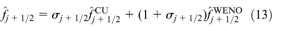
which is constructed by hybridizing a fifth-order compact upwind (CU) scheme

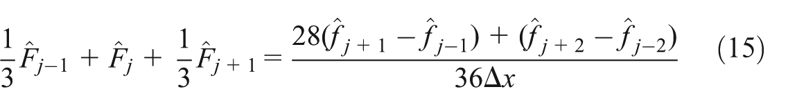
A sixth-order symmetric compact difference scheme is applied for the viscous diffusion terms
where
In order to obtain the gas velocity and temperature at a droplet position, the fourth-order Lagrange interpolation method is employed to compute the physical quantities of gas, velocities, and temperature. The position of droplet is integrated by the third-order Adams scheme, for example, in the ith direction

Computational model and simulation validations
Computational model
A two-dimensional shocked supersonic mixing layer is simulated in this study. The computational domain is taken as a rectangular area (Lx = 0.3 m, Ly = 0.1 m). The grid-set is specified as 256 × 150 nodes after the verification of grid-independence. The flow parameters of air are chosen the same as those in Goebel et al., 8 as shown in Table 1. Figure 1 shows the sketch of the physical model and calculation domain. In the shocked mixing layer flow, the IS wave, with an angle of β, is introduced from the upside of the stream 1. We chose three oblique shock angles equal to 34°, 37°, and 40° separately. After the IS impacts the mixing layer, it will refract and change its shock angle, forming the transmitted shock (TS). The top and bottom boundaries are set as infinity artificially to simulate free mixing layer flows, and hence the boundary conditions could not affect the internal flow field, and shearing vortex-waves could go out freely. The random disturbances are formed based on the most-unstable wave method 37 and added to the inflows as the velocity disturbances to inspire the flow instabilities.
Flow parameters of shocked supersonic mixing layer.


Schematic diagram of shocked mixing layer flow.
Droplets are continuously added from the central zone of inlet boundary in every computational step, and the number of releasing droplets per microsecond is 70 in all cases. The initial velocity and the temperature of droplets keep same with their surrounding gas. If the droplets move out of boundaries, they are not tracked in the calculation. Three kinds of droplet size are chosen to study the responsive capability. Table 2 shows the droplets’ properties.
Droplet parameters for the simulation.

Validation of numerical procedure
The case without shock waves is first simulated to validate the numerical procedures. The Goebel–Dutton’s experiment data 6 are used to compare to the present numerical results, as shown in Figure 2.

Comparison of self-similarity profiles with experimental data.
The profiles of mean streamwise velocity agree well with the experimental measurements. In the fully developed flow regions, the mean velocities hold statistical self-similarity. Thus, the present numerical methods are validated, which is applicable for the further study on the droplet’s response to the shock wave in the supersonic mixing layers.
Results and discussion
Dispersion of droplets in shocked mixing layer
First, oblique shock waves with different strengths are introduced at the upper boundary. The computational results of vorticity contours are shown in Figure 3. Due to the effect of oblique shock, the flow direction changes and the mixing layer deflects downward. The vortices are compressed in the direction normal to the shock due to the impacting of shock wave, resulting in a growth of the vorticity. In addition, with the increasing strength of oblique shock, the deflection angle of mixing layer increases and the vorticity of shearing vortexes is enhanced much more.

Instantaneous vorticity contours in shocked mixing layer with different strengths.
Then, droplets with different diameters are added into the flow field from the inlet of the supersonic mixing layer. Considering the incident angle of the oblique shock equals to 37°, droplets’ dispersions are shown in Figure 4.
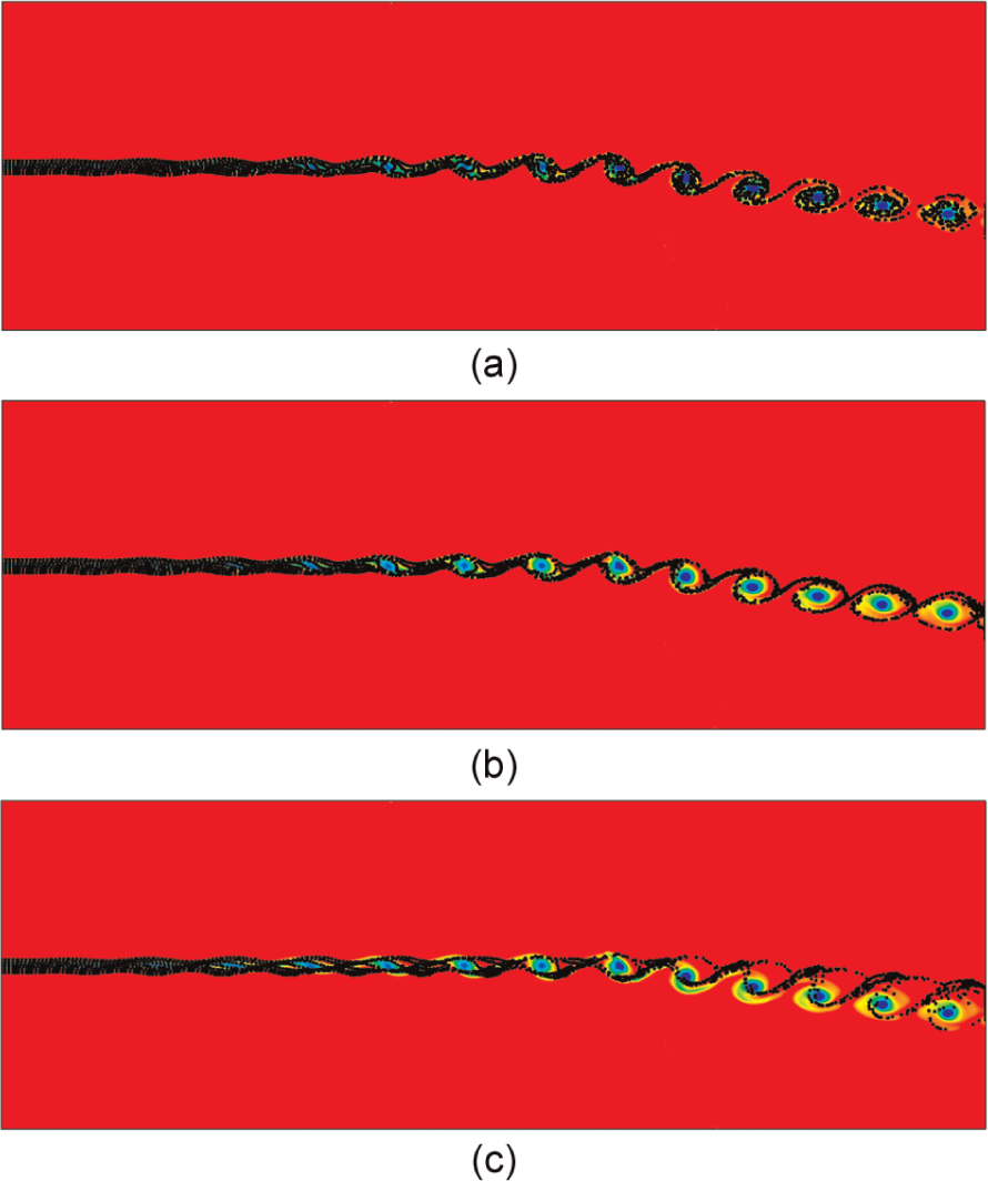
Dispersion of droplets in different diameters in shocked mixing layer with shock angle β = 37° (from top to bottom: d p = 1 µm, d p = 3 µm, and d p = 10 µm).
Although droplets are added uniformly, they distribute non-uniformly in the flow field. Droplets are affected by the eddy transportation in the mixing layer. Small droplets follow the vortices’ rotation, whose distributions are almost full of the whole vortex structure. However, large droplets mostly distribute at the outer edge of the vortex, affected by the large centrifugal force when they follow the vortexes’ rotation.
Figure 5 shows distribution of droplets near the oblique shock, demonstrating the influence of droplet size on the particle dispersion. From these partial enlargements, it is found that the dispersion of droplets with larger diameter is impacted more by the oblique shock. The oblique shock changes the deflection of vortexes immediately, since the airflow eddies respond to the shock quickly. With increasing the inertia of droplets, the effect of oblique shock on the dispersion of droplets is unobvious, and larger droplets maintain their original motion status even after the shock wave.

Distribution of droplets near the oblique shock (from left to right: d p = 1 µm, d p = 3 µm, and d p = 10 µm).
Therefore, it can be concluded that for larger droplets, they distribute densely around the vortexes, while sparsely in the center of vortexes without the oblique shock. The role of oblique shock wave results in the deflection of vortexes, but has the droplets dispersed due to the attenuated transportation of the vortexes. Large droplets could distribute in the core of the vortexes in the condition of appropriate flow parameters.
The instantaneous distribution of droplets could not present their response to the gas and this is to be detailed in the next section.
Response behavior observed in Lagrangian framework
The variations in the droplet velocity as well as temperature along its motion path are analyzed. Droplets with different diameters, released at the midpoint of the inlet boundary, are tracked, illustrating their response to the oblique shock, for instance, with β = 37°. The streamwise velocities of both two phases are converted into dimensionless ones by U inlet = (U 1 + U 2)/2, shown in Figure 6.

The momentum response of the droplet to the supersonic fluid.
After the shock wave impacting point on the mixing layer, the gas-phase velocity diminishes rapidly due to the action of shock wave. The velocity of small-sized droplet overlaps the gas-phase velocity seen by the droplet, because it follows the vortices’ movement closely and the momentum balance for two phases could finish instantly. Even though the velocity gradient of gas phase seen by the medium-sized droplet is relatively large, the velocity gradient of droplet is smoothed away, because of the comparatively large inertia. The response of the large-sized droplet to the oblique shock wave is extraordinary. The gas-phase velocity seen by the droplet has been increasing until the shock wave impacting point, after which there appears a sudden decrease. But, after this impacting point, the droplet velocity still rises in a certain degree and reduces later with negligible amplitude. Along the large droplet’s trajectory, its velocity nearly has no significant change, because the droplet moves downstream almost with the initial momentum. In conclusion, with the droplet size becoming smaller, the response to the shock wave is similar to that of the surrounding gas-phase particles, and the shock wave hardly changes its responsive performance; for the larger sized droplet, the response to the shock wave is more obvious.
Figure 7 shows the thermal response behavior for different sized droplets. The temperature is converted into dimensionless one divided by T inlet = (T 1 + T 2)/2. The thermal response time is longer than the momentum response time. Hence, compared with Figure 6, even though the small-sized droplet could finish the momentum response, it could not expeditiously finish the thermal response. The larger the droplet is, the harder it finishes the thermal response, compared with the momentum response. Although the gas-phase temperature seen by the large-sized droplet has a strong pulsation, the droplet temperature along the trajectory changes smoothly as a result of the slow responsiveness of the droplet to changes in temperature of the carrier fluid. In sum, the fast response of temperature is more difficult to achieve, compared with the momentum response.

The thermal response of the droplet to the supersonic fluid.
Response behavior observed in Eulerian framework
The time-averaged velocity and temperature of droplets are obtained in Eulerian framework after obtaining a statistically stationary solution. In order to display clearly the variation in time-averaged statistics under the influence of oblique shock (β = 37°), three profiles are chosen in different streamwise locations: x = 0.18 m (the zone before the shock–vortex interaction, denoted as P1), x = 0.19 m (the shock–vortex interaction zone, denoted as P2) and x = 0.20 m (the zone after the shock–vortex interaction, denoted as P3).
Figure 8 shows the distributions of time-averaged streamwise velocity and temperature for both two phases before the shock–vortex interaction. The shear layer has not been affected by the shock wave and transverse location of the mixing layer centerline is at the midpoint of Ly . After the IS, the gas-phase velocity decreases and temperature increases. Droplets follow the flow and response to this variation in velocity and temperature, but in different extents for different sizes. For the momentum response of droplets to gas, small-sized droplets follow the velocity change in surrounding gas, with slight difference between two phases. However, the larger the size of droplet is, the more obvious this difference becomes, indicating the more insensitively following characteristics of the larger droplet. However, the temperature distributions show that the small-sized droplets cannot respond to the rise in temperature quickly and the difference of temperature between two phases is larger than that of velocity. In the mixing zone, velocity distributions of three different sized droplets keep almost the same with the gas phase. While these droplets and gas phase have non-overlapped temperature distributions in the mixing zone.

Streamwise velocity (left) and temperature (right) distributions at P1.
The profiles at the zone of shock–vortex interaction, as shown in Figure 9, indicate the shock’s effects on both the vortices and droplets. The oblique shock changes the flow direction of mixing layer and the mixing region deflects to the negative y-axis direction, compared with that at P1. The TS wave disorganizes the gradient of streamwise velocity and temperature in the mixing region, resulting in a slow momentum response of the small-sized droplets, which have effective response capability without the influence of TS. For the medium- and large-sized droplets, they do not seem to respond to the effect of TS on the streamwise velocity and temperature distributions, since their response time scales are too longer to reflect the variation in the TS impaction region.

Streamwise velocity (left) and temperature (right) distributions at P2.
Figure 10 shows the streamwise velocity and temperature profiles of two phases when vortices have traversed the oblique shock wave. The mixing layer suffers shock wave’s spatial compression, reducing the scale of mixing layer but increasing the gradient of velocity and temperature. Small-sized droplets follow the momentum variance of gas phase well in the mixing region. The gas-phase velocity rises outside the TS impacting region and small-sized droplets could not respond to this variation immediately. Larger droplets have slower momentum responsiveness. Under the effect of TS wave, even the temperature profiles of small-sized droplets are not overlapped with those of gas phase, stating that those droplets still need time to follow the shocked fluid elements of mixing layer. Thus, the time scale of thermal response is larger than that of momentum response. The changed trend of thermal response behavior with increasing size of droplets is similar to that of momentum response behavior.

Streamwise velocity (left) and temperature (right) distributions at P3.
Conclusion and remarks
Supersonic mixing layers impinged by an oblique shock wave were numerically simulated by means of the LES coupled with the Lagrangian trajectory method. The dispersion of droplets in shear layer vortices and the response to shock waves were then discussed. In the simulation, instantaneous disturbances were imposed to the gas-phase velocity from the inlet to inspire the instabilities and developments of the mixing layer. The shock wave is introduced from one side of free streams and then impacted on the large-scale eddy structures downstream. Three kinds of droplets in diameter of 1, 3, and 10 µm were studied for their responsiveness.
The dispersion of droplets is changed much more with increasing droplet size. Due to the effects of shock wave, larger droplets are not transported by vortices in mixing layers but more dispersed after the shock wave impacting position on the mixing layer. Small-sized droplets have a short response time of momentum and heat transfer, and thus they follow the flow consistently and respond easily to the shock wave. Compared with the aerodynamic response, the thermal response to the supersonic flow hardly accomplishes, especially under the impacting of the shock wave. A fluctuant change in gas-phase temperature seen by a droplet along its trajectory is found, but the smallest sized droplets in this research could not follow this variation. The time-averaged profiles show that the difference of statistical velocity and temperature exists between droplets and gas phase. The IS wave and the TS waves change the following capability of droplets, and the momentum response is more rapid than the thermal response for the same-size droplets.
The present studies are helpful for seeking proper approaches to enhance the efficiency of fuel–oxidizer mixing in engines. The small-sized droplets with fast momentum responsiveness are conductive to high efficient mixing and perform well in combustion, but large ones may contribute to suppress the oscillation combustion. Hence, the balance of choosing the suitable fuel droplets still needs further research under the conditions of existing spraying techniques. Compared with the momentum responsiveness, the delayed thermal responsiveness of fuel droplets may cause difficulties for evaporation. In addition, the drag coefficient for droplets needs amendment in the future, since the present drag coefficient is employed as that in the steady flow.
Footnotes
Academic Editor: Hua Meng
Declaration of conflicting interests
The authors declare that there is no conflict of interest.
Funding
This work was partially funded by the Importation and Development of High-Caliber Talents Project of Beijing Municipal Institutions (No.YETP0113).