
Abstract
Opposed-piston two-stroke engine has been proposed by Beijing Institute of Technology to improve power density and complete machine balance relative to conventional engines. In order to study opposed-piston two-stroke engine scavenging flow, a scavenging system was configured using a three-dimensional computational fluid dynamics model effectively coupled to experiments. The boundary conditions are obtained through one-dimensional working process simulation results and experiments. As the opposed-piston relative dynamic characteristics of opposed-piston two-stroke engine depend on different design and operating parameters including the opposed-piston motion phase difference and crank-connecting rod ratio, a numerical simulation program was built using MATLAB/Simulink to define opposed-piston motion profiles based on equivalent crank angle of opposed crank-connecting rod mechanism. The opposed-piston motion phase difference only affects scavenging timing while crank-connecting rod ratio affects scavenging timing and duration. Scavenging timing and duration are the main factors which affect scavenging performance. The results indicate that a match of opposed-piston motion phase difference and crank-connecting rod ratio has the potential to achieve high scavenging and trapping efficiency with a right flow in cylinder.
Keywords
Introduction
Pressured by energy crisis and environmental pollution, car industry is faced with unprecedented challenges due to its high energy consumption and pollution emission.1,2 In order to keep a sustainable development, car industry will develop in the direction of zero-discharge electric drive vehicle. 3 Range-extender electric vehicle is a transitional technology which could overcome the limitation of traditional electric vehicle charging time and improve the travel distance of pure electric vehicles by adding an additional energy storage component. 4 As a form of range-extender, small generating set is used for online supplement energy, which has a small displacement, high power density, simple, and compact structure. Opposed-piston two-stroke (OP2S) gasoline direct injection (GDI) engine has some advantages in being pure electric vehicle extender, since it is simple, compact, high power density, and good balance.
OP2S engine concept can be traced back to late 1800s. Since then, many novel applications were used on aircrafts, marines, and vehicles. In the first half of the 20th century, OP2S engine was developed in multiple countries for a wide variety of applications. However, modern emission regulations stopped the widespread development of most of the two-stroke engines in the latter half of the 20th century. 5 In recent years, with the application of advanced design technology, modern analytical tools, materials, and engineering methods, the emission problem is no longer limiting the successful design of a clean and efficient OP2S, 6 so OP2S engine has again attracted intensive attention to improve engine efficiency and emission performance.7–11 Compared with conventional engines, OP2S engines have many fundamental advantages. 12 The opposed piston (OP) structure characterized by two pistons reciprocating opposite to each other in a common cylinder canceled the cylinder head and valve mechanism and leads to lower heat loss for higher wall temperature of the two piston crowns compared to a cylinder head. The nearly symmetric movement of OPs leads to excellent engine balance even for single-cylinder configuration.
In recent years, relevant studies were carried out. Stephenson et al. conducted a parametric study on the effects of swirl, initial turbulence, oxygen concentration, and ignition delay on fuel vaporization, mixing, and combustion process. The effects of intake flow field were further investigated by varying the geometry of the intake ports and intake runners in a model dual-port direct injection diesel engine in KIVA simulations. 13 Stephenson and Rutland 14 assessed the differences in the in-cylinder flow field present during combustion resulting from different intake flow configurations and compared with the significance of spray–wall interaction effects on combustion and emission performance. Bo et al. 15 assessed the accuracy of prediction of the air motion and spray characteristics in a direct injection diesel engine with the computational fluid dynamics (CFD) code. However, gas motion in the OP2S has not been sufficiently studied in the literature. In the OP2S engines, two OPs move symmetrically make the volumetric change rate is twice as large as that of the conventional engines, result in the gas motion and dissipation law are also different. The cylinder head is absence in the OP arrangement, so fuel injector must be installed in the cylinder liner, and the interaction between the fuel spray and the in-cylinder fresh-charge motion with traditionally high swirl resulted in combustion occurring near the combustion chamber surfaces. 7 Hofbauer conducted a numerical study on the effects of swirl level and nozzle parameters on wall–fuel contact and mixture formation. The results present that low swirl show a favorable effect on the formation. 10 However, since the scavenging process was not included in the calculation, the initial swirl was set as a parameter. To achieve a good swirl level and flow field by designing port structure has not been studied in the literature.
The approach by Beijing Institute of Technology (BIT) uses a uniflow scavenging and GDI technology to achieve separation of injection and scavenging process. The opposed crank-connecting rod mechanism is placed on both sides of cylinder body and a chain transmission mechanism is designed to realize synchronization working of OP. OP2S-GDI engine has some potential advantages such as simple structure, good balance, compact, high power density, and thermal efficiency. The uniflow scavenging system is the most efficient scavenging method for two-stroke engine and is also been considered for free piston engines 16 and OP engines. 17 Numerical modeling of in-cylinder flow in uniflow scavenging system has been the subject of earlier works and include steady-flow simulations,18,19 two-dimensional (2D)-axisymmetric simulations, 20 sector simulations without intake port geometry, 21 and full three-dimensional (3D) simulations.22,23 The full 3D simulations are the only approach that allows asymmetric phenomenon to be studied. Multi-dimensional CFD codes are widely used in the design and development of internal combustion engines due to their ability to investigate variables that are difficult or costly to measure in experimental tests. 24 CFD offers an expedient means for investigating the flow, gas exchange, and combustion processes under realistic engine operating conditions and identification of important features and major underlying interactions between them. 25
Although OP2S engine has already been commonly modeled and tested by many researchers, most of these researches focus on the basic engine performance; they are unable to identify details of the engine design and operating parameters. The article provides some insights into multi-dimensional gas flows in scavenging process of OP2S-GDI engine using commercial CFD software AVL-FIRE based on numerically simulated OP motion profiles and evaluates the scavenging performance using different design and operating parameters, namely, OP motion phase difference and crank-connecting rod ratio. One-dimensional (1D) simulated in-cylinder and scavenge case pressure and temperature were used to define the boundary conditions. The model is validated by comparison of model predictions and experimental data. The mixing of cylinder gas is examined and the concentration of fresh charge in the cylinder at exhaust port closing (EPC) is estimated. The transient behavior of the angular and axial momentum in the engine cylinder is studied over full engine cycle.
Engine modeling
Engine configuration
As shown in Figure 1, OP2S-GDI engine is equipped with GDI system and a uniflow scavenging system, and its injector and spark plug are placed on cylinder liner. On both sides of cylinder liner, there are gas ports, intake ports on one side, and exhaust ports on the other side. Intake ports are used to deliver fresh air into the cylinder, and exhaust ports are used to deliver burnt gas out from the cylinder. In the working process, piston motion controls the opening and closing of ports. There are two pistons placed in cylinder liner, and a combustion chamber is formed when the two pistons move to the closest position. The piston that controls the opening and closing of intake air ports is defined as intake piston and the piston that controls the opening and closing of exhaust air ports is defined as exhaust piston. When the distance between the two pistons is minimized, it is defined as the inner dead center (IDC); when the distance between the two pistons is maximized, it is defined as the outer dead center (ODC). The structure parameters are shown in Table 1.

OP2S-GDI engine.
Engine specifications.

BSFC: brake-specific fuel consumption.
Scavenging description
Figure 2 illustrates the principle of uniflow scavenging process of OP2S gas exchange. The exhaust port opens first before ODC and a blow down discharge process commences. The discharge period up to the time of the scavenging port opening is called the free exhaust period. The intake port opens also before ODC when the cylinder pressure slightly exceeds scavenging pressure. Because the burned gas flow is toward the exhaust port, which is now having a large open area, the exhaust flow continues and few backflow occurs. When the cylinder pressure is less than the scavenging pressure, fresh air enters the cylinder and the scavenging process starts. This flow continues as long as the intake port is opened, and the scavenging total pressure exceeds the pressure in the cylinder. As the pressure rises above the exhaust pressure, the fresh charge flowing into the cylinder displaces the burned gas: a part of the fresh air mixes with the burned gas and is expelled with them. The intake port closes after the exhaust port closes; since the flow is toward the intake port continuously, additional fresh air is obtained. The additional air inflow period up to the time of intake port close is called the post intake period.
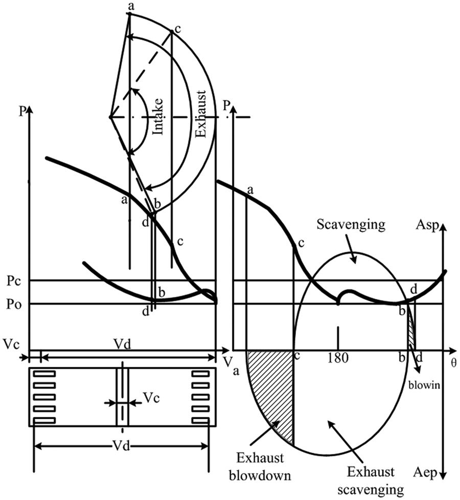
Gas exchange in OP2S engine.
OP2S-GDI engine dynamic
In the application of the current mainstream CFD code such as star-CD and AVL-FIRE, researchers need structural parameters of crank-connecting rod system or a predefined piston motion profile to simulate piston movement. As the piston relative motion profile of OP2S engine is different from that of conventional engine, the existing work on the CFD modeling of OP2S engines uses piston motion profiles obtained from a dynamic engine model. In this article, piston motion profile was obtained from a dynamic calculation which is built by MATLAB/Simulink. As shown in Figure 3, due to OP motion phase difference, OPs on both sides cannot arrive at each top dead center (TDC) simultaneously. If the phase difference of the intake and exhaust pistons is

where
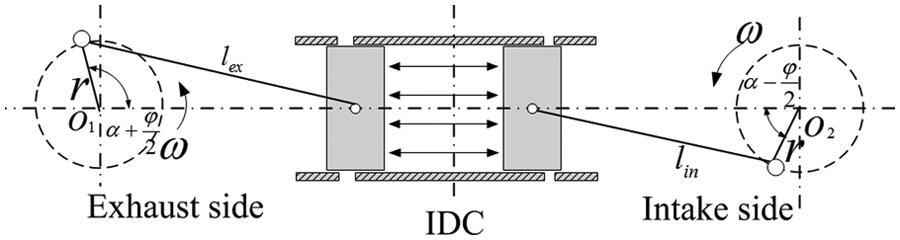
Opposed crank-connecting rod mechanism.
When
Taking the derivative of equation (1) about

Taking the derivative of equation (2) about,

CFD model and setup
AVL-FIRE software is used to build CFD model in working process simulation. The dynamic mesh tool Fame Engine is used to generate the moving meshes of the cylinder by defining moving selection, buffer selection, interpolation selection, and the relative motion rule of OP. Intake and exhaust chambers generated no moving meshes which are refined near the intake and exhaust ports, in order to capture the significant flow gradients accurately. The moving parts were meshed with layered hexahedrons with the layers being normal to the movement of the piston. Since the geometry of the scavenging port was very irregular, it was meshed with hybrid grids, including tetrahedrons, prisms, and hexahedrons to avoid divergence and ensure the accuracy of the results. Figure 4 shows the full-scale 3D CFD model consisting of 249,528 cells at scavenging process and 47,961 cells at compression process after rezone. Dynamic mesh of piston motion in the intake and exhaust strokes has been treated according to the realistic motion rule of OP. The scavenging calculation is from exhaust port opening (EPO) to intake port closing (IPC), while the in-cylinder process is from IPC to EPO.

CFD calculation model.
Mesh movement includes three parts: left and right pistons to simulate the gas motion during the entire working process.
Boundary and initial conditions
The boundary conditions were chosen to reflect the physical conditions in the validation model and the prototype engine. A constant pressure boundary condition is used for both intake and exhaust ports. The mean scavenge pressure is taken as 1.2 bar and the mean exhaust receiver pressure is taken as 1 bar. Frictional effects at the walls are not taken into account, that is, the smooth wall option for turbulent flow boundary condition is used. The initial conditions in the cylinder are extracted from the GT-Power software simulation for every case. The flow field is initialized by specifying the temperature, pressure, and turbulence intensity. By performance prediction, initial in-cylinder pressure and temperature are computed in the case of 15 kW at 6000 r/min, which are the initial conditions for CFD. The initial temperatures of cylinder, intake chamber, and exhaust chamber are given a value of 784 K, 322 K, and 634 K, respectively. The constant wall temperatures were also used.
Model validation
Uniflow scavenging process is assumed to be completed in three models: perfect scavenging, perfect mixing, and short circuit. In practice, scavenging process includes multiple scavenging models, giving a relation for scavenging efficiency

where
The boundary and initial conditions of CFD calculation are given by 1D simulation. Meanwhile, coupling simulation characteristic of 1D and 3D can be adopted for model testing.
9
The experiment carried out 1D and 3D scavenging process comparison validation on the above five cases at 6000 r/min. As shown in Table 2, given scavenging model index
Comparison between scavenging results.

1D: one-dimensional; 3D: three-dimensional.
When
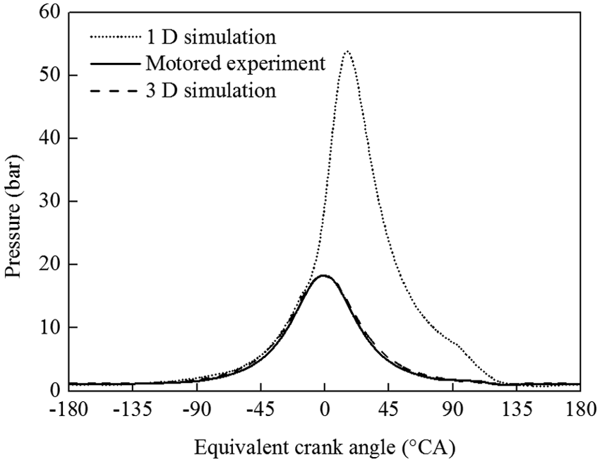
Comparison between in-cylinder pressures.
Simulation results and discussion
Scavenging process
Piston relative motion profile of OP2S is determined by

Intake and exhaust piston displacement: (a) effect of
Variation in the scavenging timing and duration.

EPO: exhaust port opening; IPO: intake port opening; EPC: exhaust port closing; IPC: intake port closing.
The mass flow through intake ports during scavenging is presented in Figure 7. The mass flow increases rapidly at first after IPO and reaches a maximum with slow fluctuations before ODC. After mass flow reaches a maximum, the mass flow shows a linear decreasing trend. In-cylinder pressure at IPO depends on the time of EPO and the free exhaust period and the in-cylinder pressure at IPC depends on the time of EPC and the post intake period. A longer EPO advance and a shorter intake closing delay can avoid the blow black of burnt gas and fresh charge at the time of IPO and closing. A larger

Mass flow through the intake port: (a) effect of
Figure 8(a) shows the
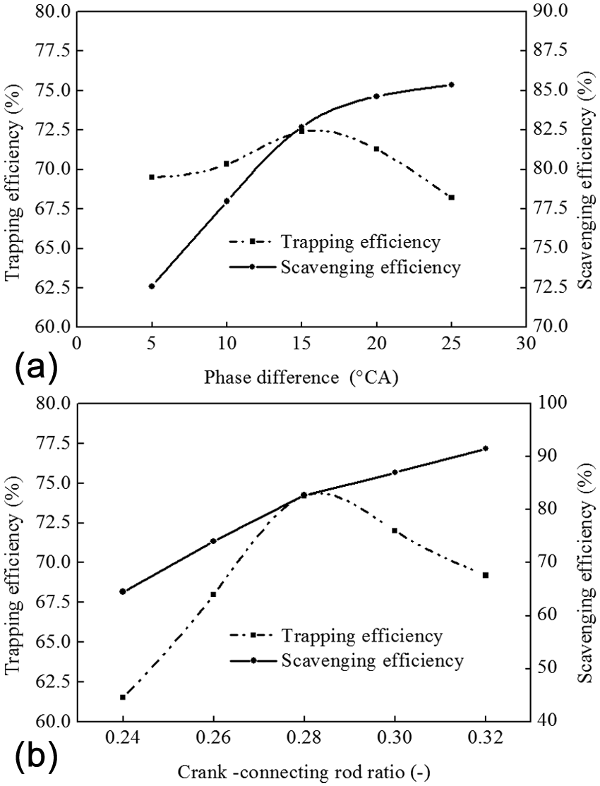
Scavenging results of different design and operating parameters: (a) effect of
Scavenging flow
Figure 9(a) shows when OP is around IDC, the greater the

Intake and exhaust piston relative velocity: (a) effect of
This special dynamic characteristic may influence OP2S engine performance by affecting gas motion in the cylinder. As shown in Figure 10, due to relative movement of OPs in compression and expansion process, in-cylinder gas momentum near cylinder middle section is counteracting. Affected by phase difference, piston movement velocity is not 0 and the direction is the same around IDC during intake and exhaust. Therefore, air axial motion velocity is not 0. As shown in Figure 10(a),
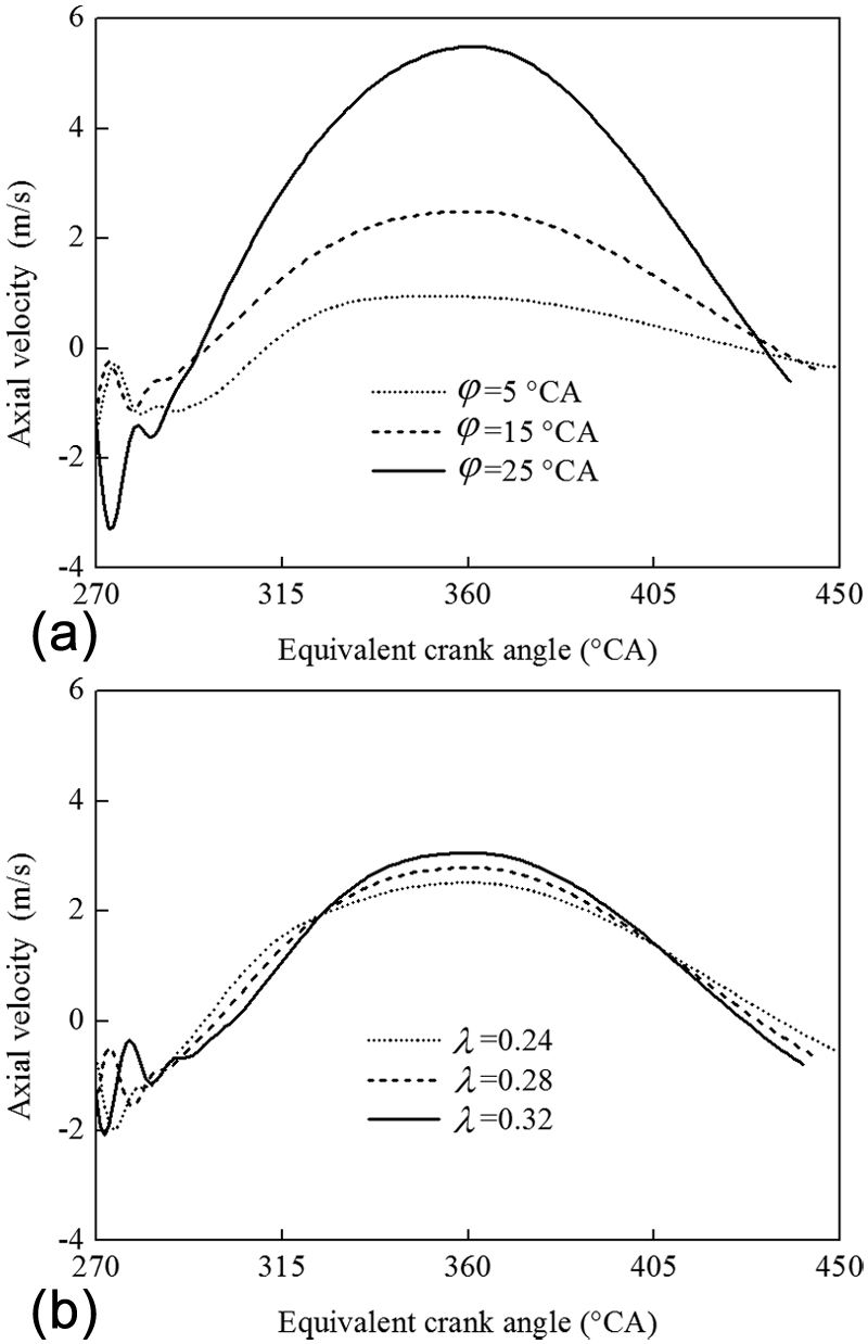
Axial velocity of gas in the engine cylinder: (a) effect of
Figure 11 shows the effect of

Swirl ratio of gas in the engine cylinder: (a) effect of
Turbulence kinetic energy (TKE) is defined as mean kinetic energy per unit mass associated with eddies in turbulent flow. Figure 12 shows that the in-cylinder mean TKE changes tend to be uniform in compression process. The result can be attributed to two reasons: as cylinder axial motion velocity increases, small vortex breaks into turbulence; since the velocity of piston motion is nonzero in IDC and gas exchange near pistons is active, TKE increases rapidly. When piston motion moves to IDC, mean TKE changes slowly due to eddy shearing and dissipation. The result also finds that maximum mean TKE grows with the in increase in OP relative velocity before IDC. At the IDC, although minimum working volumes of different

TKE of gas in the engine cylinder: (a) effect of
Angular and axial gas motion
To quantify the transient behavior of the system, the volume integrated angular and axial momentum in the engine cylinder are evaluated when

where V is the instantaneous cylinder volume,
The variation in the angular and axial momentum over the engine cycle is presented in Figure 13 using the angular momentum at ODC Lz , ODC and the cylinder radius B/2 for normalization. As the exhaust starts at EPO, a rapid decrease in the angular momentum is observed in Figure 13(a). The decrease is caused by burnt gases being blown out through the exhaust port due to the high in-cylinder pressure. As the fresh charge is blown into the cylinder with a tangential velocity component, a rapid increase in the angular momentum is observed. The maximum angular momentum is obtained approximately after ODC. Before EPC, an unexpected reduction in the angular momentum is observed. This drop is mainly caused by the decrease in intake mass flow velocity due to the increase in in-cylinder pressure and decrease in gas ports flow area by the inward motion of the OP. From IPO to ODC, the change in angular momentum shows a delay caused by the flow inertial. The angular momentum is minimized at 8°CA after IPO and the angular momentum is maximized at 40°CA after ODC. Figure 13(b) shows that the axial momentum of the cylinder charge is not 0 at IDC because the absolute velocity of OP is not 0 unlike the conventional engine at TDC when the piston motion phase difference is not 0. As the piston begins to move outward, the fluid gain momentum is reduced. At EPO, the cylinder charge is directed out through the exhaust port and the axial momentum increases rapidly. At IPO, the cylinder charge again gains momentum due to the fresh charge entering from the intake port. After ODC, the axial momentum decreases as the mass flow rate through the intake ports decreases. The closing of the exhaust port creates pressure waves that travel between the OP surfaces. The pressure waves are observed as small superimposed oscillations on the curve after EPC and IPC. At IPC, a pressure wave is again created traveling between the OP surfaces. A decrease at 30°CA after ODC is, however, observed, corresponding to a decrease in mass flow rate. After EPC, the oscillations decrease and the pressure increases in the compression process.

Angular and axial momentum in the cylinder: (a) angular momentum in the engine cylinder and (b) axial momentum in the engine cylinder.
Conclusion
In this article, a CFD model is developed, validated, and applied for investigating the scavenge flow in the OP2S uniflow scavenging engine. The model gives detailed information on the temporal development of in-cylinder flow field with different design and operating parameters, namely,
The
Different
The
During compression process, swirl ratio decreases gradually due to wall friction and dissipation. The
The angular momentum of in-cylinder gas is delayed by 8°CA after IPO due to inertia effect on in-cylinder flow and the maximum angular momentum occurs at 40°CA after ODC.
Footnotes
Academic Editor: Jose Ramon Serrano
Declaration of conflicting interests
The authors declare that they have no conflict of interests regarding the publication of this article.
Funding
This research received no specific grant from any funding agency in the public, commercial, or not-for-profit sectors.