
Abstract
This article presents a numerical study of active vibration control of smart composite laminates in the presence of actuator debonding failures. A comparison between the smart composite laminates with healthy actuator and various partially debonded actuator cases is performed to investigate the debonding effects on the vibration suppression. The improved layerwise theory with Heaviside’s unit step function is adopted to model the displacement field with actuator debonding failure. The higher order electric potential field is adopted to describe the potential variation through the thickness. The finite element method–based formulations are derived using the plate element, taking into consideration the electro-mechanical coupling effect. The reduced-order model is represented by the state-space form and further for the vibration suppression using a simple constant gain velocity feedback control strategy. For the purpose of demonstration, a 16-layer cross-ply substrate laminate ([0/90]4s) is employed for the numerical study. The results show that the actuator debonding affects the closed-loop frequencies, active damping ratios, and efficiency of vibration suppression.
Introduction
Vibration suppression of flexible smart structures by piezoelectric actuators and sensors has been comprehensively studied during the past decades.1,2 As one of the most commonly used smart materials, the piezoelectric materials are usually bonded on the surface or embedded into the host structures, working as actuators and sensors. The host structure, such as a laminated plate, with distributed actuators and sensors can be used in controlling precision instruments, vibration suppression, and so on. However, the debonding failures between the piezoelectric elements and the host structures may occur during the service life, due to high peeling stress concentrating at the bonding edge. As a result of debonding, the dynamic behaviors of structures and the actuation and sensing capabilities will be weakened. Moreover, the closed-loop system may also be affected and even destabilized. Therefore, it is of vital importance to investigate the debonding effects on the active control of smart structures.
Numerous modeling methods have been developed for smart composite laminated structures with piezoelectric layers or distributed actuators and sensors in the presence of delamination failures.3,4 Delamination detection5,6 in smart composite structures has also attracted a lot of attentions in structural health monitoring. However, there are less works on modeling and active control of smart composite laminated structures with partially debonded actuators. In the late 1990s, Seeley and colleagues7,8 developed the finite element (FE) modeling of adaptive composites including the debonding using a penalty approach and examined the debonding effect on the mode shapes and frequencies. A sublaminate technique was developed by Raja et al. 9 for composite beams and plates with debonding failures. It was implemented by imposing the strain-based multipoint constraints to satisfy the continuity condition of displacement across the delaminated edge. The interfacial debonding effects on the dynamic behaviors of surface-bonded piezoelectric actuators were investigated by Jin et al., 10 taking into consideration the debonded adhesive layers. Sun et al. 11 studied the actuator and sensor debonding effects on active control of beam structures for both the collocated and non-collocated control schemes. They found that the debonding location at the middle had very little effect on the active control performance. Kumar et al. 12 investigated the optimal control of smart plates with partially debonded actuator, and they found that the debonding influenced both the active damping and the active stiffening effects. From these works, the debonding effects on the system responses have been inspected in both static and dynamic aspects, and it has been found that the presence of debonding failures reduces the control capabilities of the active structures besides changing the dynamic characteristics.
The focus of this article is to evaluate the actuator debonding effect on the active control performance of a laminated plate. Among the feedback control algorithms, the constant gain velocity feedback (CGVF) control,13–15 the constant amplitude velocity feedback (CAVF) control,14,16 and the linear quadratic regulator (LQR) optimal control17–20 are the most widely used control strategies for active control of smart composite laminated structures. To better understand the actuator debonding effect, active control of a smart composite laminate with distributed actuator and sensor including the actuator debonding failure is studied in this article, using an improved layerwise theory. The improved layerwise theory was first developed by Kim and colleagues21–24 for delamination failures in composite laminates, using the Heaviside unit step function to address the discontinuity of displacement field. This theory is also possible to address the discontinuous displacement caused by actuator debonding. Considering the electro-mechanical coupling,25–27 the higher order electric potential field is adopted to describe the potential variation through the thickness. For the plate with piezoelectric patches, the general FE method can be used to derive the governing equation with plate element. The governing equation can be further expressed into the state-space form using the reduced-order model. The classical CGVF control strategy is applied to investigate the active vibration control of a smart composite laminate with actuator debonding failure. Numerical studies with a 16-layer cross-ply ([0/90]4s) substrate plate are performed with various debonding sizes to investigate the actuator debonding effects on the closed-loop frequencies, system damping ratios, and control efficiency.
Improved layerwise theory for smart composite laminate
The improved layerwise theory developed by Kim et al. 23 for smart composite laminate is adopted to model the actuator debonding failure. For the geometry given in Figure 1, one piezoelectric actuator and one piezoelectric sensor are surface bonded on the top surface of a substrate plate. The actuator and sensor are bonded close to the clamped root to achieve good actuation and sensing performance. Thus, for a system with piezoelectric elements, the linear constitutive relations considering the electro-mechanical coupling behavior can be expressed in the matrix form as follows


Geometric configuration of smart composite laminate with surface-bonded piezoelectric actuator and sensor.
where
To model the actuator debonding failure in smart composite laminate, the kinematics is modeled using the improved layerwise theory 23 which is based on the following displacement field
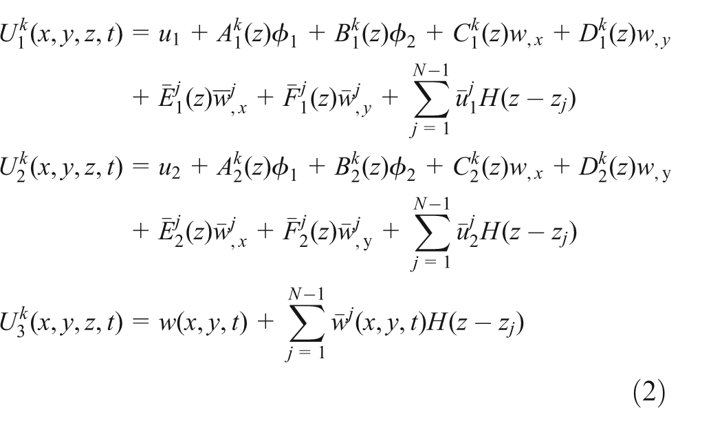
where k denotes the kth layer of the laminate. The quantities
In equation (1), the debonding can be simulated by the value of Heaviside unit step function through controlling the interface

The electric potential function

where
The electric field

The smart composite plate is discretized by four-node rectangular element, with eight structural degrees of freedom

where
The detail formulations can be found in the established FE method.24,28 Then, the governing equations can be obtained by the extended Hamilton’s principle as follows

where
By integration by part and the variational principle, equation (7) can be simplified and the governing equation can be obtained and written in the matrix form as follows
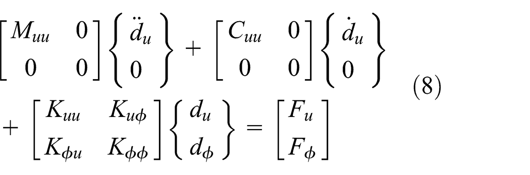
where Muu
, Cuu
, and Kuu
are the mass, damping, and stiffness matrices, respectively;
The proportional viscous damping is adopted which is the simplest damping case and easy to be implemented in the linear vibration analysis
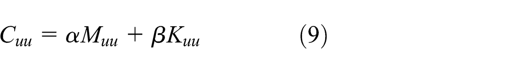
where
By the matrix condensation, the governing equation becomes the following form in the presence of both mechanical and electric inputs

where

Active controller design
Modal form
The FE discretization leads to a large number of degrees of freedom; therefore, it requires the use of reduced-order model, where it only employs m lower modes that dominate the global response of the system. In the general modal reduction method, the undamped free vibration equation results in the following eigenvalue problem
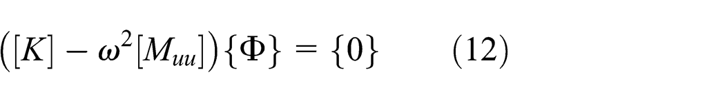
where
Assuming that the system response is governed by the first m modes, the following modal coordinate transformation can be introduced using the modal vector matrix

where
Substituting equation (13) into equation (10) and left multiplying
where

Because of the orthogonality of the mode shapes,
State-space representation
The model control theories require the system in the state-space representation, in which the second-order multi-degrees-of-freedom system is described by a first-order matrix differential equation. The reduced-order governing equation, equation (14), can be expressed in the state-space form as follows

where X is the state vector and A is the system matrix. The matrices

The output equation, only considering the sensor output

where

Note that the voltage output can be measured by the relation between the structural output and the coupling stiffness matrix, which is condensed in the FE model.
Feedback control law
After defining the system in the state-space form, a direct output feedback control algorithm is employed in this study to investigate the control efficiency of smart composite laminate when there is actuator debonding failure. In the direct output feedback control, a CGVF control is utilized which is one of the most widely used control strategy in the vibration suppression of smart laminated structures. It attenuates the vibration amplitude by enhancing the system damping, known as the active damping. The control input voltage is defined as

where G is the velocity control gain.
Substituting equation (20) into equation (16) and with the help of equation (18), it yields

where
In the above closed-loop system, the choice of control gain G determines the poles of the system through changing the active damping. The gain selection and control system design can be done using root-locus method or Nyquist method. However, it is worth noting that the control voltage applied on the actuator should not exceed the depoling voltage. Exceeding the maximum allowable voltage of the actuator may cause the depolarization of the piezoelectric materials. Thus, the maximum amplitude of the response should be examined to estimate the range of control gain before implementing the active control. When the estimated control voltage exceeds the maximum allowable voltage, the design should be repeated using a new control gain.
Results and discussion
The active vibration control is studied in this section for the smart composite laminate using the material properties given in Table 1. The piezoelectric actuator and sensor possess the same mechanical and electric properties. A 16-layer cross-ply plate ([0/90]4s), with the dimension size 30 cm × 6 cm, is discretized into 60 × 12 elements in length and width direction. The structural damping ratios are chosen as 0.0001 for both
Material properties of composite laminate and piezoelectric material.


Actuator debonding location and sizes.
First six natural frequencies (Hz) of the open-loop system.

Vibration control with healthy actuator
In this subsection, a CGVF control algorithm is applied to the control of smart composite laminate with healthy actuator. When determining the control gain, as described earlier, it should not exceed the maximum allowable voltage of the actuator. With G = 0.05 and 0.1, the poles of open-loop system and closed-loop system are shown in Figure 3. It is observed that only the closed-loop system poles of the first, third, and fifth modes (bending modes) are changed and the poles of the second, fourth, and sixth modes (twisting modes) remain the same. This is because the bending modes dominate the system response and the twisting modes are negligible for the given geometry. It is also observed that for the three bending modes, only the closed-loop poles of the first mode move to the left side of its open-loop poles in the complex plane, and the poles of the third and the fifth modes move to the right side of their open-loop poles, since we know that in the left side of the complex plane, if the poles locate far from the y-axis, the system converges fast. While the poles locate close to the y-axis, the system converges slowly. This indicates that the first mode is well controlled, while the third and the fifth modes are enhanced. The closed-loop frequencies and active damping ratios with G = 0.05 and G = 0.1 are computed using the truncated model and shown in Table 3. It is observed that the first and the fifth natural frequencies decrease, and the third natural frequency increases compared with the open-loop natural frequencies, when applying the feedback control. The damping ratios have positive values for all modes, ensuring the stability of the closed-loop system. It has to be noted that when the gain is increased from 0.05 to 0.1, the active damping of the first mode increases from 3.61% to 5.95%. While for the third mode and the fifth mode, the damping ratios decrease which implies that the control performance is reduced for these two modes.

System poles of open-loop system and closed-loop system with control G = 0.05 and 0.1 for healthy laminate.
Three bending frequencies and active damping ratios of the closed-loop system for healthy laminate.

The healthy composite laminate is subjected to 1 N mechanical impulse load at the tip center for the time period of 10 ms to investigate the control efficiency. The open-loop and the closed-loop responses of the tip displacement are shown in Figure 4(a). It is found that with the control gain G = 0.05 and G = 0.1, the system responses are well controlled for both cases. The settling times are 0.5 s for the G = 0.05 case and 0.3 s for the G = 0.1 case, which indicates that the large gain case shows the faster vibration suppression performance. The frequency responses for the tip displacement are further calculated by performing the fast Fourier transform (FFT) on the time responses, as shown in Figure 4(b). The frequency response curves present three peaks, representing three bending modes. From the graph, it is observed that the amplitudes of the controlled responses are significantly attenuated in the first mode, but they increase in both the third and the fifth modes. The time response and frequency response curves of the sensor output are shown in Figure 5(a) and (b). Since the sensor output is based on the induced strain, the output voltage follows the tendency of the displacement and the amplitude is dependent on the vibration intensity. It can also be concluded that the voltage output converges very fast when applying the feedback control, and the G = 0.1 case converges faster than the G = 0.05 case. From the frequency aspect, similar conclusion can be obtained. The first mode is well suppressed, while the third and the fifth modes are enhanced. However, since the first mode dominates the vibration of the plate and possesses the largest vibration energy in this case, the control performance is very well by attenuating the first mode only. The control voltage signals are shown in Figure 6 for two control gains. In the velocity feedback, the control input is representative of the strain rate. Thus, the control voltage shows large value at the beginning and decreases as the vibration velocity decays. The peak values of the control voltage are 45.2 and 100.3 V for G = 0.05 and G = 0.1 cases, respectively.
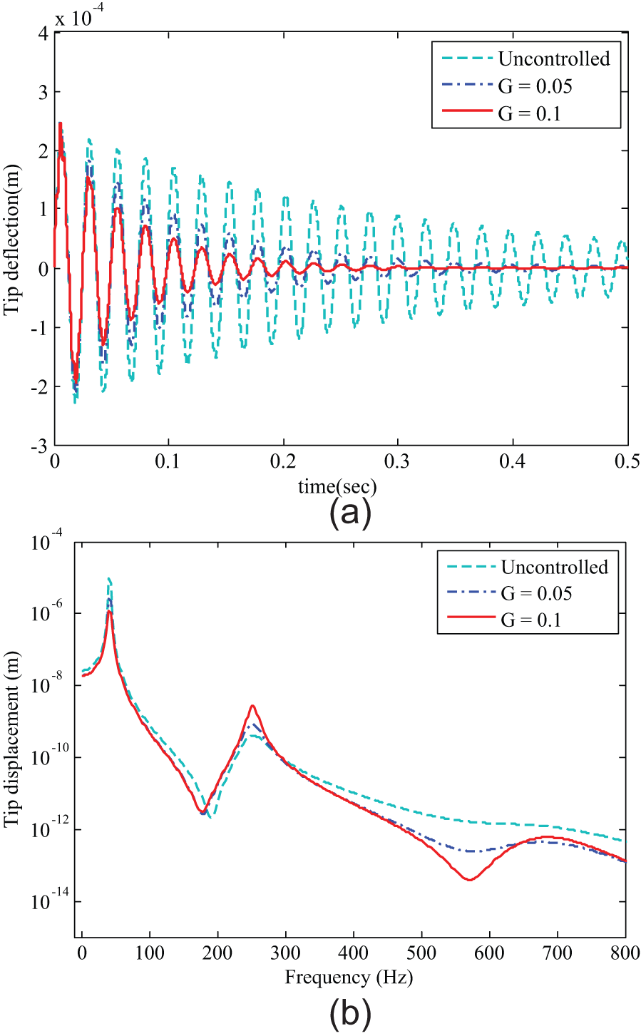
(a) Uncontrolled and controlled tip displacement for healthy smart composite laminate subjected to 1 N impulse load at the tip center. (b) Frequency response of tip displacement for healthy smart composite laminate subjected to 1 N impulse load at the tip center.
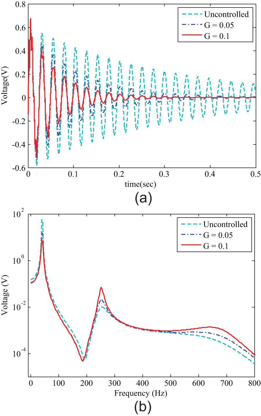
(a) Uncontrolled and controlled sensor output for healthy smart composite laminate subjected to 1 N impulse load at the tip center. (b) Frequency response of sensor output for healthy smart composite laminate subjected to 1 N impulse load at the tip center.

Control input voltage for healthy smart composite laminate subjected to 1 N impulse load at the tip center.
Vibration control with actuator debonding failures
To investigate the actuator debonding effects on the control capability, the CGVF control algorithm is applied to the smart composite laminates with partially debonded piezoelectric actuator. The debonding size and location are defined as shown in Figure 2. To investigate the debonding effect, the debonding is assumed to occur at the right edge of the actuator only since the debonding location at the middle has very little effect on the active control and the closed-loop frequencies. 11
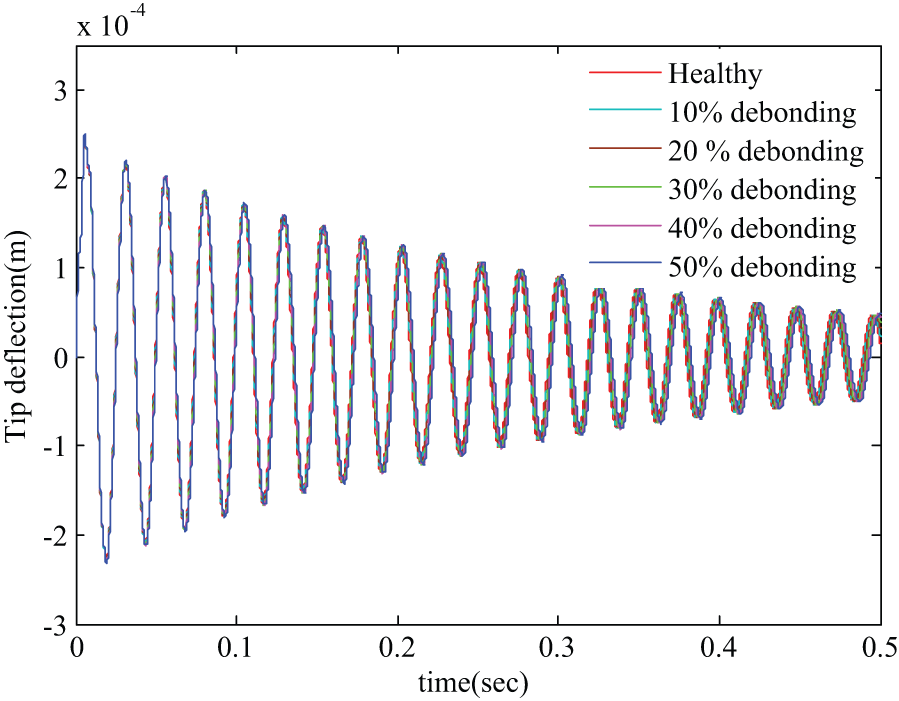
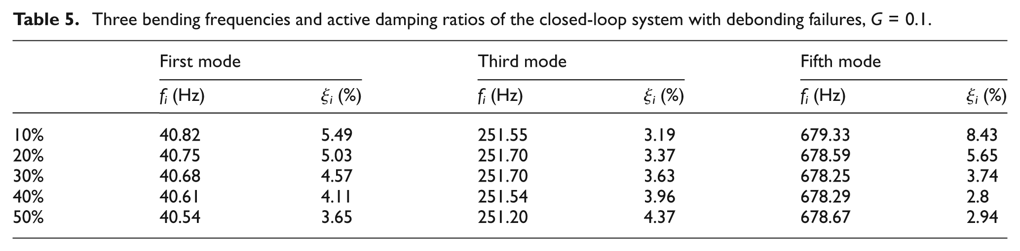
The open-loop system responses of the tip displacement and sensor output are shown in Figures 7 and 8 for the healthy laminate, and five debonding cases subjected to 1 N mechanical impulse load at the tip center. Both the two graphs show that there is no significant difference in the magnitudes between the healthy laminate and debonded laminates. This is because the debonding slightly affects the structural stiffness and the laminate is excited by mechanical force only. The frequency shift can also be observed which is in accordance with that listed in Table 2. The closed-loop frequencies and active damping are shown in Tables 4 and 5 for the debonding cases with G = 0.05 and G = 0.1. From the tables, it is found that the closed-loop frequencies are also changed due to the existence of debonding failure. For the active damping ratios, first, they increase with the increase in control gain for the first mode, but they decrease for the third and fifth modes. Second, the active damping ratios decrease with the increase in the debonding size for the first and the fifth modes, but they increase for the third mode. Since previously we have already found that the first mode dominates the vibration, it can be inferred that with larger control gain and smaller debonding size, the first mode can be suppressed more efficiently and the control performance is better.
Effect of actuator debonding size on the tip displacement of the open-loop system response subjected to 1 N impulse load at the tip center.
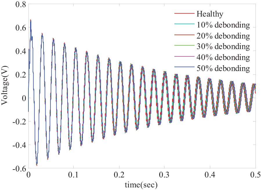
Effect of actuator debonding size on the sensor output of the open-loop system response subjected to 1 N impulse load at the tip center.
Three bending frequencies and active damping ratios of the closed-loop system with debonding failures, G = 0.05.

Three bending frequencies and active damping ratios of the closed-loop system with debonding failures, G = 0.1.
The closed-loop system responses are shown in Figures 9 and 10 with the control gain G = 0.1. First, the vibration is suppressed well for both the tip displacement output and sensor output. But it presents different control performance for various debonding cases. The settling times with respect to various debonding sizes are shown in Figure 11. The settling time is denoted when the amplitude is less than 1% of the maximum peak value. It is found that the settling time increases with the increase in the debonding length. The healthy laminate reaches the stable state in the shortest time, while the 50% debonding case takes the longest time to reach the stable state. This result also correctly reflects that the debonding causes the reduction in control capability of piezoelectric actuator. The control voltage is also investigated and shown in Figure 12. Since the same control gain is used and the structural response differences at the beginning are quite small, the peak values of the control input are similar. The amplitude of the control input also follows the tendency of the system response and the input voltage settles along with the displacement.
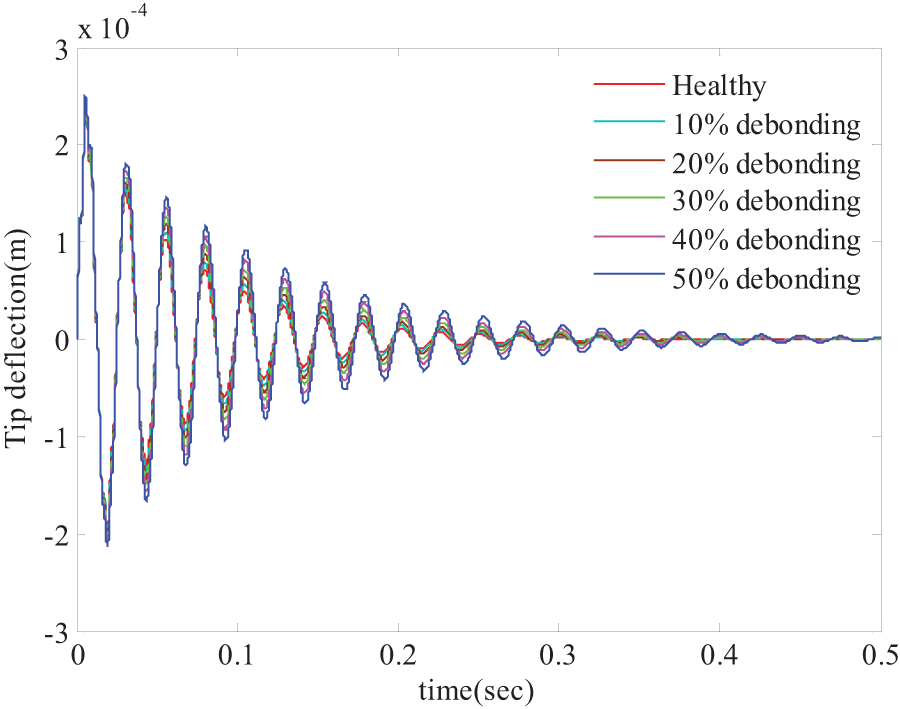
Effect of actuator debonding size on the tip displacement of the closed-loop system response subjected to 1 N impulse load at the tip center, G = 0.1.

Effect of actuator debonding size on the sensor output of the closed-loop system response subjected to 1 N impulse load at the tip center, G = 0.1.

Settling time of the closed-loop response with respect to various debonding lengths using constant control gain G = 0.1.

Control input voltage of healthy and debonded laminates subjected to 1 N impulse load at the tip center.
Conclusion
Active vibration control of smart composite laminates with actuator debonding failures has been performed using the CGVF control strategy. An FE model based on the improved layerwise theory which fully incorporates the electro-mechanical coupling effect has been developed to obtain the dynamic response of the structure. The reduced-order model has been developed and further transferred into the state-space form for the controller design. A CGVF controller has been designed to suppress the vibration of smart composite laminates with and without actuator debonding failures. The control gain effects on the closed-loop frequencies and active damping ratios of healthy laminate and damaged laminates have been investigated. The actuator debonding effects on the open-loop system and closed-loop system have also been investigated. With the existence of actuator debonding failure, it has been found that the settling time increases significantly with the increase in the debonding length, which indicates that the control efficiency is reduced dramatically. The proposed modeling and control algorithm reveal the actuator debonding effect on the active control efficiently and accurately. However, in practice, the system is very sensitive to the control gain value and the control input voltage is in proportion to the gain value, leading to the difficulties of choosing a proper gain value. Thus, in the future, it is necessary to design the controller for investigating the actuator debonding effect on active control using optimal control strategies to make a comparison.
Footnotes
Academic Editor: Martin Jun
Declaration of conflicting interests
The authors declare that there is no conflict of interest.
Funding
This work was supported by the National Research Foundation of Korea (NRF) grant funded by the Korea government (MSIP) (No. 2013R1A2A1A01015171).