
Abstract
In China, cooling water entering cooling towers still retains surplus pressure between 39,240 and 147,150 Pa. In order to utilize this wasted energy, it is suggested that the surplus water energy can be harnessed to drive a type of hydroturbine installed in the inner platform of cooling tower and make the fan rotate via its coupled shafts. However, conventional hydroturbines are not suited for this job because of their low efficiency or unmatched rotating speed with that of the fan under the operating conditions of cooling towers. In this article, according to the requirements of turbine work environment in cooling towers, a new type of hydroturbine, Francis turbine with ultra-low specific speed (ns = 50 m.kW), was designed to replace the fan motor in a cooling tower. Primarily, the shape, position, and number of runner blades were designed and optimized through theoretical analyses and computational fluid dynamics simulations. Additionally, metal elliptical volute and single-row ring guide vanes were applied to scale down the structural dimensions. Finally, the optimal scheme of the new Francis turbine was proven to have a high efficiency of 88% and good operation stability through testing of a physical model and can achieve the goal of harvesting renewable energy in the cooling tower.
Keywords
Introduction
A cooling tower is a heat removal device used to transfer waste heat absorbed in the circulating cooling water systems to the atmosphere.1,2 The water contacts the air to dissipate the industrial waste heat. At present, most of the fans used in cooling towers are driven by motors that consume large amounts of electric energy. However in China, water circulating in cooling water systems still keeps a surplus pressure between 39,240 and 147,150 Pa due to an excessive design margin, which is often wasted in the throttle valve. In order to utilize wasted energy, it is suggested that the surplus water energy can be harnessed to drive a type of hydroturbine installed in the inner platform of cooling tower and make the fan rotate through its coupled shafts, as shown in Figure 1. However, conventional hydroturbines are not suited for this job due to the operating conditions of cooling towers and fan parameters.

Schematic diagram of a cooling tower with a fan driven by a turbine.
Zhang 3 used a Pelton turbine to recover the waste energy of a cooling tower, and his test results showed that the limited installation space of the cooling tower forced the Pelton turbine runners to be entirely submerged in water, so that its efficiency decreased greatly. Chen 4 improved a Pelton turbine used in cooling towers and recommended another turbine type, the Francis turbine. Although a Francis turbine usually has high efficiency, its higher rotating speed does not match with that of the fan and requires a corresponding reducer, which makes the entire device structure complex and large in dimension. Many studies have been carried out to improve the hydraulic performance of Francis turbines used in cooling towers,5–8 while the efficiency of these turbines was not sufficiently high. Therefore, a new type of hydroturbine should be designed to fit the working conditions of the cooling tower. With the advancement of computer technology and computational fluid dynamics (CFD), more researchers have used CFD methods to analyze the characteristics of the fluid machinery such as pumps and turbines.9–11 In this article, a new type of Francis turbine with an ultra-low specific speed was studied and developed through CFD simulations and experimental methods. It had smaller dimension, high efficiency, and low cost and could meet the need of the cooling tower well.
Basic parameter design
Specific speed
In this study, a new Francis turbine was designed aimed at a given cooling tower, where the discharge of recycled water was 0.833 m3/s and surplus water head was 13 m. The fan installed in this cooling tower rotated at a rated speed of 136 r/min, and the motor power was 91 kW.
The specific speed ns is an important parameter to classify hydroturbines as to their types and proportions. It is calculated by the following formula
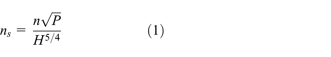
here, n, P, and H are the rotating speed, output power, and water head of the hydroturbine, respectively. Additionally, the unit speed n 11 is another important parameter and calculated by equation (2)

For a given cooling tower, substituting the parameters above into equation (1), the ns of the new Francis hydroturbine is equal to 52.6 m·kW, which is very low compared to the conventional Francis hydroturbines used in power stations. According to the relation between Francis hydroturbine dimensions and specific speed 12 as well as the limited installation space in the cooling tower, the basic parameters of this new Francis hydroturbine were determined and listed in Table 1.
Basic parameters of the new type of Francis hydroturbine.

It is worth mentioning that to reduce the horizontal size of the new Francis hydroturbine, single-row guide vanes, instead of the normal double-row vanes, were used to provide both water diversion and load supporting. Likewise, the shapes of spiral case sections are all elliptical, and a taper draft tube with a cone angle of 13° was employed.
The schematic of the new Francis hydroturbine is shown in Figure 2.

Schematic of the new type of Francis hydroturbine.
CFD simulation results
Numerical simulation method
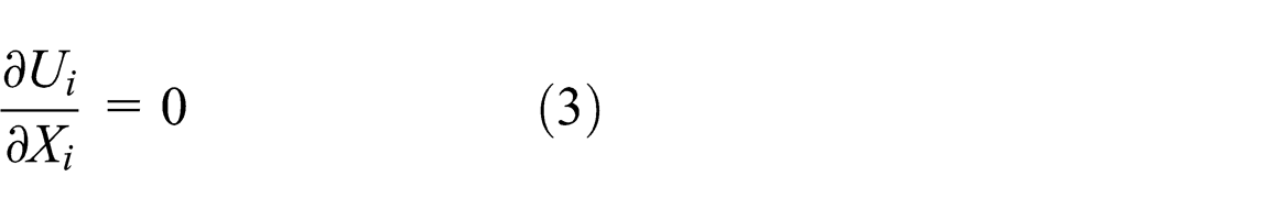
Three-dimensional turbulent steady simulation of the Francis turbine was conducted using Fluent 6.2 software. 13 For the fluid flow analysis of this turbine, the continuity equation and Reynolds-averaged Navier–Stokes equation for steady incompressible flow were used in the following form

where
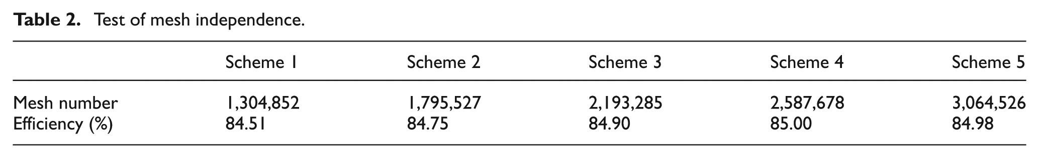
With the considerations of the grid sensitivity and the personal computer’s (PC) computing capability, unstructured tetrahedron elements were chosen and built by Gambit meshing software. 17 The mesh independence was also checked as shown in Table 2. We found that when the total number of meshes exceeded 2.59 million, the result was more or less independent of the mesh refinement for schemes 4 and 5.
Test of mesh independence.
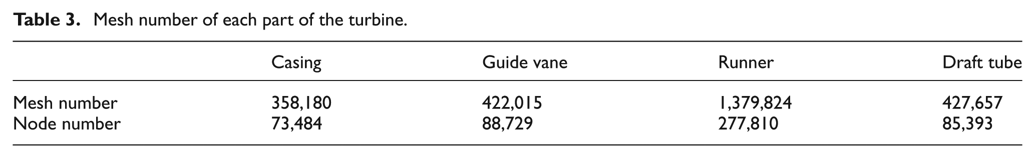
Therefore, the results from mesh scheme 4 were used to perform the analysis, and the mesh number of each turbine passage part is shown in Table 3.
Mesh number of each part of the turbine.
Numerical results of the initial scheme
Through three-dimensional steady simulation, it was found that the discharge Q was equal to 0.845 m3/s and the torque M was 6436 N m when the water head H was set as 13 m and n = 136 r/min. Then, the efficiency
Total pressure in every flow section.
Hydraulic loss in the turbine passage can also be calculated with the following formula

herein, (P inlet − P out) is the total pressure difference between the passage inlet and outlet, and ρ and g are the water density and acceleration of gravity, respectively. From Table 4, it can be found that hydraulic loss mainly exists in the guide vanes region and reaches 10.5%, that is, 1.41 m.
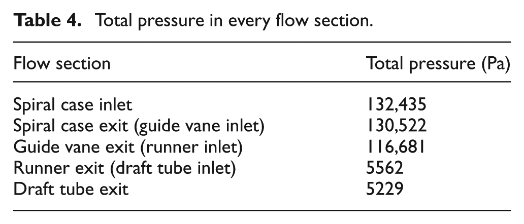
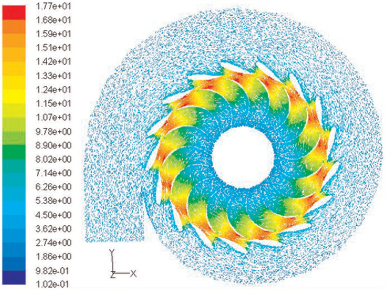
The inner flow fields of initial scheme are described to reveal the characteristics of the ultra-low specific speed turbine. Figure 3 shows that the static pressure decreases gradually and clearly from the leading edge to the trailing edge on the blade’s pressure side, and localized low pressure appears near the leading edge of blade’s suction side, which is caused by the high velocity developed between the guide vanes and runner blades, illustrated in Figure 4. Figure 4 also displays that the velocity in the runner inlet region is generally high with the maximum velocity more than 17 m/s, which demonstrates kinetic energy to be the main form of energy acting on the runner blades. From Figure 5, it can be concluded that the flow pattern in the runner is uniform because streamlines of relative velocity distribute smoothly in the blade-to-blade channel.

Static pressure distribution on the runner blades (Pa).
Absolute velocity vector field in the horizontal cross-section located in the half height guide vane (m/s).
Streamlines of relative velocity in runner blades’ channels.
Numerical results of an improved scheme
Although the turbine power of the initial scheme can meet the power requirement of the fan, the deficiency is also clear for its exceeded discharge and excessive hydraulic loss in the guide vanes region. Therefore, an improved scheme was designed through shape modification for both the guide vanes and the runner blades, shown in Figures 6 and 7. In terms of the improved scheme, one side of the guide vane profile was adjusted to make it slender, and the airfoil bending angularity of the runner blade was increased simultaneously.

Guide vane shape comparison between the two schemes.

Runner blade shape comparison between the two schemes.
Through CFD simulation, the parameters of the improved scheme were obtained as follows: discharge Q = 0.835 m3/s, torque M = 6620 N m, efficiency η = 88.5%, and power P = 94.2 kW. The total pressure in every flow section was also calculated and listed in Table 5.
Total pressure in every flow section for the improved scheme.
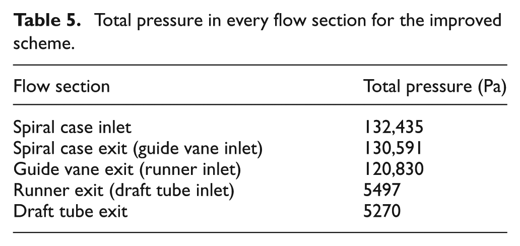
According to Table 5, the hydraulic loss in the guide vane region is reduced to 7.4% because the value of the absolute velocity decreases by nearly 0.5 m/s for the wider guide vane channel when comparing Figure 8 with Figure 9.

Absolute velocity contours in the guide vane-to-vane channel of the initial scheme (m/s).

Absolute velocity contours in the guide vane-to-vane channel of the improved scheme (m/s).
The peripheral speed of the draft tube entrance is more obvious in Figure 10. However, it almost disappears in Figure 11 due to the increased airfoil bending angularity of the runner blade, which is also beneficial to the reduction of hydraulic loss for low specific speed turbines. 18

Streamlines of absolute velocity in the draft tube entrance section of the initial scheme.

Streamlines of absolute velocity in the draft tube entrance section of the improved scheme.
Experimental measurements
The ultra-low specific speed Francis turbine was manufactured according to the improved scheme. Experiments have been performed in the test rig of hydraulic machinery through changing water head from 5 to 16.5 m under a constant rotating speed of 136 r/min (Figure 12). Test results showed that the maximum efficiency reached 88%, as well as H = 11.6 m and Q = 0.794 m3/s, which was 0.5% less than that of the CFD results. When H = 12.66 m and Q = 0.848 m3/s, the turbine could produce 91 kW of power.
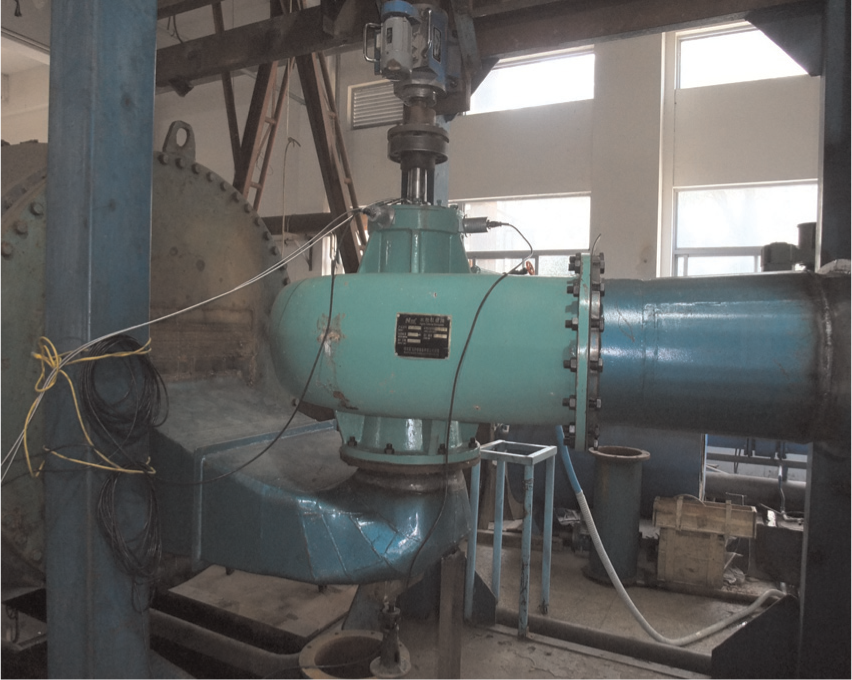
Test site of the new type of Francis turbine.
Figure 13 shows that the efficiency of CFD results agrees well with that of test results between n 11 = 39 and 43 r/min, and the best efficiency point of the test results shifted right toward larger n 11 values because the surface roughness of the turbine passage was found larger than normal by inspection.
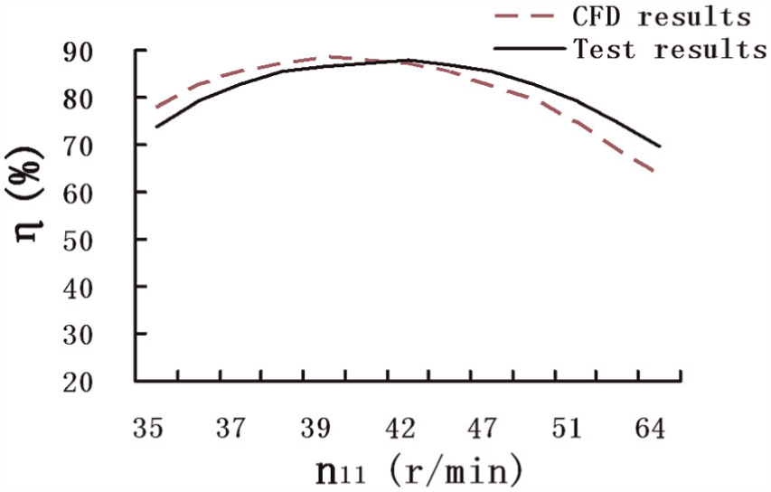
Efficiency and unit speed curves.
Overall, the Francis turbine with ultra-low specific speed was proven to be capable of completely replacing the motor to drive the fan, achieving the goal of utilizing renewable energy in the cooling tower.
Conclusion
Through CFD simulations and experimental tests, an ultra-low specific speed Francis turbine was developed, which can completely replace the motor to drive the fan for its high efficiency, achieving the goal of utilizing renewable energy in cooling towers.
Most of the hydraulic loss was found in the guide vane region. Therefore, further optimization of the guide vanes should be done for turbine performance improvement.
The high flow velocity in the guide vane region and long-narrow shape runner blades cause the passage surface roughness to be one of the crucial factors affecting turbine efficiency.
Footnotes
Appendix 1
Acknowledgements
The support of College of Energy and Electrical Engineering, Hohai University, China, is gratefully acknowledged.
Academic Editor: Mario L Ferrari
Declaration of conflicting interests
All authors declare that there is no conflict of interest regarding the publication of this article. All authors do not have a direct financial relation with the commercial identities mentioned in this article that might lead to a conflict of interest for any of the authors.
Funding
The research work was funded by Chinese National Foundation of Natural Science (No. 51106042).