
Abstract
Strength research is always one of the study focuses of face gear drives. However, a strength calculation solution, in which bending stresses, contact stresses, and bulk temperatures are included, combined with gear design standards for face gear drives, is still not constructed due to complex face gear teeth. Thus, in this study, an equivalent face gear tooth is proposed by assessment of geometric characteristics of face gear teeth and tooth contact analysis, and a strength calculation solution of face gear drives, which is based on ISO 6336 standard associated with the proposed equivalent face gear teeth, is constructed. The fidelity of the proposed strength calculation solution of face gear drives is verified by comparing its results with the benchmark of results by finite element methods. Furthermore, the impact of geometric parameters on the strength of face gear drives is investigated, and some design suggestions are extracted. These contributions would benefit the improvement of engineering applications of face gear drives.
Keywords
Introduction
Gear strength, including bending stresses, contact stresses, and bulk temperatures, is always one of the fundamental researches of gear drives. There is a vast amount of literatures discussing the strength of gear drives in the past few years. Pedersen 1 employed asymmetric gears and shape optimization to improve bending stresses of spur gears. Tesfahunegn et al. 2 studied the effect of tooth profile modifications on bending and contact stresses of spur gears. Deng et al. 3 investigated contact and bending stresses of a theoretical assembling straight bevel gear pair. Sánchez et al. 4 proposed a non-uniform model to assess the bending stress of spur and helical gears. Gorla et al. 5 evaluated the bending and contact fatigue strength of an innovative steel for large gears. Handschuh et al. 6 predicted the impact of tooth spacing errors on root stresses of spur gear pairs. Sánchez et al. 7 constructed a calculation solution for tooth-root stresses of high transverse contact ratio spur and helical gears. Spitas et al. 8 examined the impact of tooth depths and cutter tip radii on the bending strength of 20° involute gear teeth. Wang et al. 9 checked contact stresses of spur gear drives by finite element method (FEM). Similarly, the strength research is one of the important study contents of face gear drives, which can be defined as intersection gear drives with a spur gear. Litvin et al.10,11 investigated stresses of two versions of geometry of face gear drives, and Litvin cooperated with Gonzalez-Perez et al. to predict bending stresses of face gear dives with a helical gear. Guingand et al. 12 tested quasi-static bending stresses of a face gear drive under torsional conditions. However, according to the limited published issues about the strength of face gear drives, a strength calculation solution of face gear drives associated with gear strength standards is still not constructed, which is caused by complex face gear teeth. Thus, in this study, an equivalent face gear tooth is proposed by assessment of geometric characteristics of face gear teeth and tooth contact analysis (TCA), and a strength calculation solution of face gear drives, which is based on ISO 6336 standard associated with the proposed equivalent face gear teeth, is constructed. The fidelity of the proposed strength calculation solution is verified by comparing its results with the benchmark of FEM results. Moreover, the impact of geometric parameters on strength of face gear drives is discussed, and some design suggestions for improving the strength of face gear drives are obtained. These contributions would be helpful to accelerate engineering applications of face gear drives.
Strength calculation solution of face gear drives
A face gear tooth, as shown in Figure 1, can be considered as a sequence in which modified involute gears are superimposed along its face width. Meanwhile, at extreme outer radii, its tooth would be pointing, namely, positive modifications, and at extreme inner radii, its tooth would be undercut, meaning negative modifications.

A diagram of face gear teeth.
In Figure 1, a face gear tooth can be divided into two parts: one is the positive modification area and the other is the negative modification area. Therefore, a reference circle, namely, a non-modified position along face widths, must exist, and its radius can be obtained as

Meanwhile, the extreme inner and outer radii can be derived in a piecewise form as
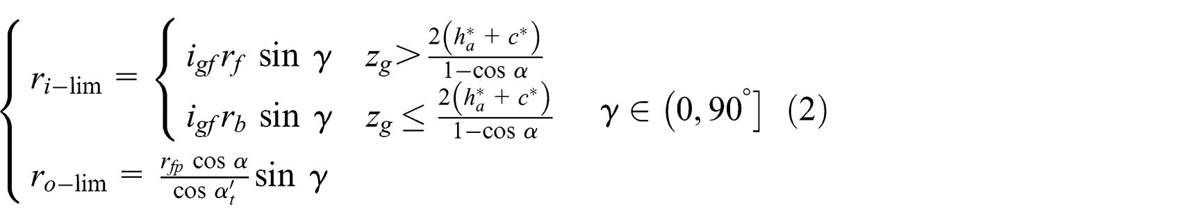
and the modified coefficients versus the extreme radii can be deduced in a piecewise form as

where γ is the shaft angle, m is the module, rf
is the dedendum radius of generation gears, rb
is the base radius of generation gears, α is the pressure angle,
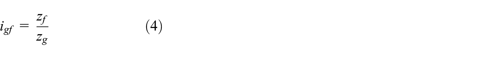
In order to avoid offset load phenomenon of face gear drives, the tooth number of pinions, which mesh with a face gear, is always less one to three teeth than generation gears, which are employed to generate face gears. Thus, the contact position of face gear drives would not be at the radius of reference circles on face gear teeth, but it must exist at the negative modification area of face gear teeth, due to fewer teeth. The modified coefficient of the contact position can be extracted as

where zp is the tooth number of pinions.
The spacing between the reference radius and the contact position along face widths of face gear teeth can be derived by

Therefore, the contact radius on face gear teeth can be given as

According to equation (7) and the proposed geometric modeling solution of face gear teeth, a contact section on face gear teeth can be obtained as shown in Figure 2.

A contact section on face gear teeth.
As illustrated in Figure 2, a contact section on face gear teeth is a modified involute profile. Thus, based on contact viewpoints, face gear drives can be equivalent as involute gear drives. Meanwhile, the equivalent face width of face gear teeth can be considered as the minimum diameter among long axles of contact ellipses of face gear drives. According to Hertz formulas, 13 the equivalent face width of face gear teeth can be deduced as

where F is the load, γp and γf are Poisson’s ratios, Ep and Ef are moduli of elasticity, rp and rf are the contact radii, and µ and ν are the elliptic integral factors.
According to the above equivalent face gear drives, a strength calculation solution of face gear drives, which is based on ISO 6336 standard associated with the proposed equivalent face gear teeth, can be constructed.
Verification
In order to verify the fidelity of the proposed strength calculation solution of face gear drives, a case is conducted by two calculation versions: one is by using the proposed calculation solution and the other is by FEM. The geometric parameters, material characteristics, and operating conditions of the face gear drive case are listed in Table 1.
The parameters of a face gear drive case.

A finite element model of face gear drives that employed the geometric parameters listed in Table 1 is shown in Figure 3. Meanwhile, the analytical diagrams of the bending stress, contact stress, and bulk temperature by FEM are given in Figures 4–6, respectively. In addition, the results based on the proposed strength calculation solution and FEM are listed in Table 2.
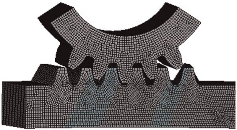
A finite element model of the face gear drive case.

Analysis of bending stresses by FEM: (a) a diagram of bending stress on pinions and (b) a diagram of bending stress on face gears.
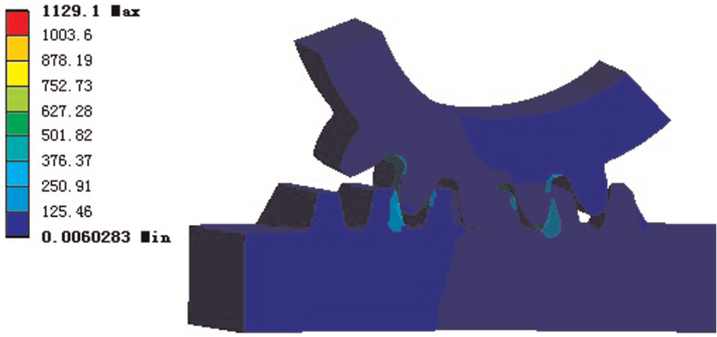
Analysis of contact stresses by FEM.

Analysis of bulk temperatures by FEM.
The bending and contact stresses and bulk temperature by two calculation versions.

FEM: finite element method.
In the case of Figures 4–6 and Table 2, the calculation difference between the two versions can be defined as
where S FEM is the results by FEM and S ISO is the results based on the proposed strength calculation solution. The calculation differences are listed in Table 3.
The calculation differences between two versions.

According to the limited simulative date in Tables 2 and 3, the results of employing the proposed strength calculation solution match satisfactorily with the FEM results in this issue. Thus, the proposed strength calculation solution of face gear drives, namely, using ISO 6336 standard associated with the proposed equivalent face gear teeth, can be acceptable.
Influence predictions
In order to predict the influence of geometric parameters on the strength of face gear drives, several cases with different geometric parameters, as listed in Table 4, are simulated, and in the simulation, when a single geometric parameter changed, the other geometric parameters are employed as the values in the first column of Table 4. The analytical results, meaning the influences of geometric parameters on the strength of face gear drives, including bending stresses, contact stresses, and bulk temperatures, under the cooperating conditions as listed in Table 1, are given in Figures 7–11, respectively.
The geometric parameters of several cases.


Influence predictions only with modulus change.
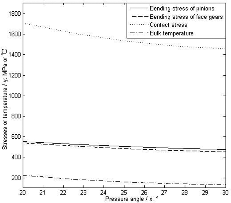
Influence predictions only with pressure angle change.

Influence predictions only with shaft angle change.

Influence predictions only with pinion tooth number change.

Influence predictions only with drive ratio change.
According to the limited analytical predictions of stresses and temperatures of face gear drives in the case of Figures 7–11, under the same operating conditions and only considering a single geometric parameter changed, bending stresses, contact stresses, and bulk temperatures of face gear drives would be decreased with the increase in module or pressure angles or pinion tooth numbers or drive ratios. Oppositely, they would be increased with the increase in shaft angles. Thus, based on the analysis in this issue, some design suggestions for improving the strength of face gear drives can be obtained as follows:
Employ a big drive ratio;
Choose a pinion with more tooth numbers;
Use a big pressure angle;
Consider a small shaft angle.
Conclusion
In the study, three important works can be extracted as follows:
An equivalent face gear tooth solution is constructed by analysis of geometric characteristics of face gear teeth and TCA.
The fidelity of the proposed strength calculation solution of face gear drives, namely, using ISO 6336 standard associated with the proposed equivalent teeth, is verified by comparing its calculation results with the benchmark of FEM results.
The influence predictions of geometric parameters on the strength of face gear drives are discussed, and some design suggestions for improving stresses and bulk temperatures of face gear drives are obtained.
These contributions not only resolve the problems of strength calculations of face gear drives caused by complex geometry of face gear teeth but also give some design suggestions for improvements of face gear strength. Thus, these contributions would be helpful to improve engineering applications of face gear drives in the future.
Footnotes
Academic Editor: Xiaotun Qiu
Declaration of conflicting interests
The authors declare that there is no conflict of interests regarding the publication of this article.
Funding
The authors are grateful for the financial support provided by the National Natural Science Foundation of China under no. 51105194 and no. 51375226 as well as the Fundamental Research Funds for the Central Universities under no. NS2015049.