
Abstract
Gyroelastic body refers to a flexible structure with a distribution of stored angular momentum provided by fly wheels or control moment gyroscopes. The angular momentum devices can exert active torques to the structure for vibration suppression or shape control. This article mainly focuses on the placement optimization issue of the actuators and sensors on the gyroelastic body. The control moment gyroscopes and angular rate sensors are adopted as actuators and sensors, respectively. The equations of motion of the gyroelastic body incorporating the detailed actuator dynamics are linearized to a loosely coupled state-space model. Two optimization approaches are developed for both constrained and unconstrained gyroelastic bodies. The first is based on the controllability and observability matrices of the system. It is only applicable to the collocated actuator and sensor pairs. The second criterion is formulated from the concept of controllable and observable subspaces. It is capable of handling the cases of both collocated and noncollocated actuator and sensor pairs. The illustrative examples of a cantilevered beam and an unconstrained plate demonstrate the clear physical meaning and rationality of the two proposed methods.
Keywords
Introduction
In order to suppress the structure vibrations of large flexible spacecraft, D’Eleuterio and Hughes1,2 introduced the concept of gyroelastic body. It refers to a flexible body in which each volume element possesses an infinitesimal quantity of stored angular momentum. The momentum devices can directly exert control torques on the flexible structure, making it quite suitable for distributed control. D’Eleuterio and Hughes1,2 have studied the dynamics and modal characteristics of the constrained (also known as pinned or cantilevered) gyroelastic body and the unconstrained (which means the free–free boundary condition) gyroelastic vehicle. Damaren and D’Eleuterio3,4 investigated the system controllability and observability and the optimal control for vibration suppression and attitude stabilization. In recent years, several studies more related with the engineering application of this concept were conducted. Yang et al. 5 adopted a scissored pair of control moment gyroscopes (CMGs) to maneuver and suppress the vibration of a flexible truss. Shi and Damaren 6 mounted a single-gimbal CMG at the tip of a cantilevered beam for active damping. Peck and Cavender have performed some concept validations of the gyroelastic theory on the Honeywell’s momentum control system and line-of-sight testbed.7,8 It was demonstrated that embedding angular momentum in the structure could shift the system frequency, couple and decouple modes, reconfigure structure damping and change the steady-state shape. Therefore, the gyroelastic body is believed as a potentially powerful technique for active control of large space structures.
In practical applications, the angular momentum devices and sensors have to be pointwise (discrete CMGs, reaction wheels, and discrete angular rate sensors). The placement of these actuators and sensors has to be considered first when designing a gyroelastic structure. However, it is somewhat surprising that few studies investigated the optimal placement problem of the actuators–sensors for the gyroelastic body. Only two similar studies are found in the open literature. Yang et al. 5 performed an optimization approach to place the scissored pair of CMGs along the flexible truss where the interaction between the CMGs and the truss is minimal. Chee 9 found the optimal distribution of double gimbaled control moment gyroscopes (DGCMGs) for vibration suppression of elastic bodies. He assumed that a series of DGCMGs were placed uniformly across a flexible structure and then the amount of the angular momentum stored by the spinning wheels was optimally allocated. It can be seen that Yang et al.’s study is oriented toward a specific problem, while Chee’s work focuses on the distribution of the amount of the angular momentum, rather than the placement of the CMGs. Therefore, this drives the motivation of this study.
Similar problem emerges while using piezoelectric materials to achieve active damping for flexible structures. Much effort has been devoted to find the optimal placement of the piezoelectric actuators, some of which can be viewed as references for optimizing the distribution of CMGs for the gyroelastic body. Devasia et al. 10 formulated three performance criteria for the problem of simultaneous placement and sizing of distributed piezoelectric actuators. Wang and Wang 11 defined a controllability index to select the optimal locations and sizes for the piezoelectric actuators. Zhang and Erdman 12 found the optimal placements of the piezoelectric actuators to maximize the controllability and observability of the controlled modes while minimizing those of the residual modes. Bruant et al. 13 adopted genetic algorithm to maximize two cost functions to ensure good controllability and observability of the structure. Other similar works can be found in Li et al., 14 Halim and Moheimani, 15 and Ducarne et al. 16
However, there exists an essential difference between the piezoelectric actuators and the distributed CMGs—the mass and inertia of the piezoelectric material are negligible, whereas the angular momentum devices will significantly change the mass property of the system. Gyroelastic bodies with different distribution of stored angular momentum will exhibit different gyroelastic modes.1,2 Therefore, we proposed two different approaches to optimize the distribution of the CMGs on a gyroelastic body. Their results can be compared to guide the design of gyroelastic structures. The first approach assumes only one pair of collocated CMG, and angular rate sensor is mounted at each of the candidate locations in turn. So, the influence of the mass property of the actuators on the gyroelastic body is minimum. A controllability index and an observability index are derived from the system controllability and observability matrices to decide which location is better. On the other hand, the second method assumes that all the candidate locations are simultaneously equipped with the CMGs and angular rate sensors. Therefore, it represents the case where the mass and inertia of the gyroelastic body are most influenced. The intersection subspaces of the controllable subspaces and the observable subspaces are calculated. The gyroelastic modes are projected to these subspaces to define a cost function which serves as the gross measure of the modal controllability and observability. It should be noted that both the two approaches just require calculating the optimization indexes for the candidate locations on a gyroelastic body and do not require calling any nonlinear optimization programming.
The remainder of this article is organized in the following format. Section “Linearized dynamics and state-space model” introduces the linearized dynamics of the constrained and unconstrained gyroelastic bodies. Modal analysis is performed, and the results are used to transform the linearized model to a loosely coupled state-space form. In section “Optimization approaches,” two optimization criteria are introduced. Numerical examples of a constrained beam and an unconstrained plate are given in section “Numerical example.” The conclusions are made in section “Conclusion.”
Linearized dynamics and state-space model
In the initial work of the gyroelastic body,1–4 the equations of motion are derived on the assumption that a continuous distribution of gyricity (stored angular momentum) exists on the system. The detailed dynamics of angular momentum devices is not incorporated. However, the actuators must be discrete CMGs or reaction wheels in engineering application. Therefore, we adopt equation (7) in Hu et al. 17 as the mathematical model of a gyroelastic body since it considers the interactions between the actuators and the flexible structure, as well as the dynamics of the actuators. As for the sensors, the angular rate sensors are adopted.
It should be noted that some concerns about the practical engineering applications, such as the static and dynamic imbalance and the dead zone issue of the CMGs and the dynamic characteristics of the angular rate sensors, are not included in the following formulations. It is assumed that the angular rate sensors are ideal, since we just focus on their mounting positions, whereas only the CMGs’ gimbal directions and the magnitude of the angular momentum of the rotors are considered.
In what follows, the equations of motion for a gyroelastic body are introduced and linearized to provide the dynamics model for the optimization approach. Both the constrained and unconstrained boundary conditions are considered.
Constrained gyroelastic body
A cantilevered gyroelastic body
where

where
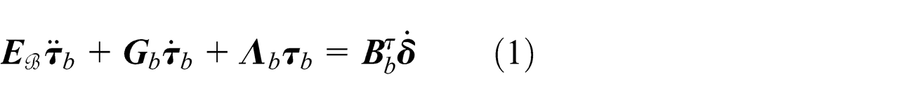
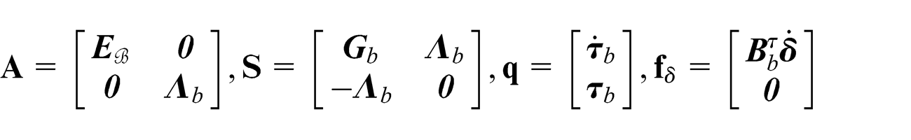
Equation (1) can be rewritten in a first-order form to perform modal analysis1,2

where

A cantilevered gyroelastic body with n CMGs and the reference frames and vectors for describing this system.
Suppose

where

where

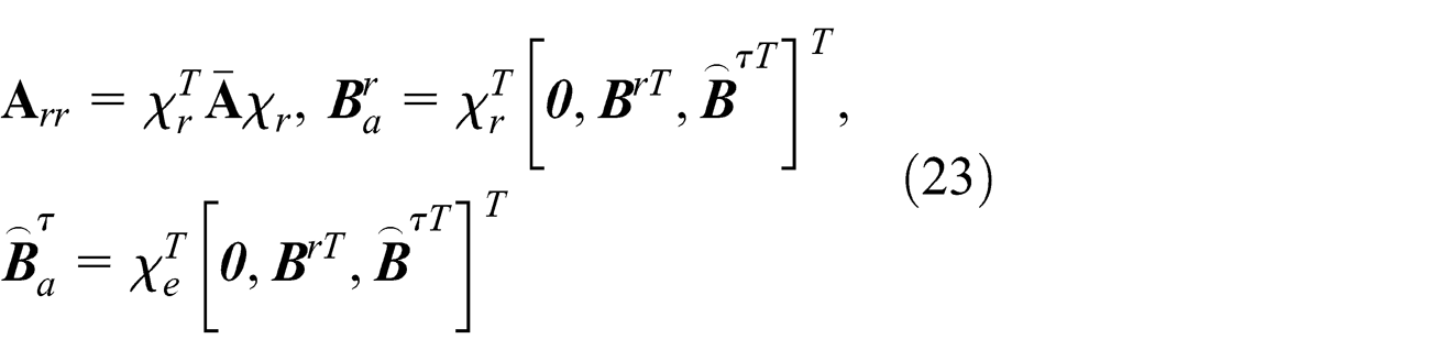
Substituting equation (6) into equation (3) and using the orthogonality conditions given by equation (4), the linearized equations of motion of the constrained gyroelastic body are written as

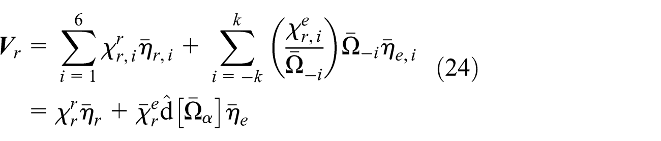
where
The angular rate sensor in Shi and Damaren 6 is adopted here. Because the gyroelastic body is constrained, the outputs of the sensors are the inertial angular velocities of the mounting locations

where
where

Equations (7) and (10) constitute the state-space model of the constrained gyroelastic body.
Unconstrained gyroelastic body
Dropping all the nonlinear terms in equation (7) of the Hu et al., 17 we have the linearized equations of motion of an unconstrained gyroelastic body (Figure 2), given by the following two equations representing the rigid motion and the elastic vibration, respectively


where


where
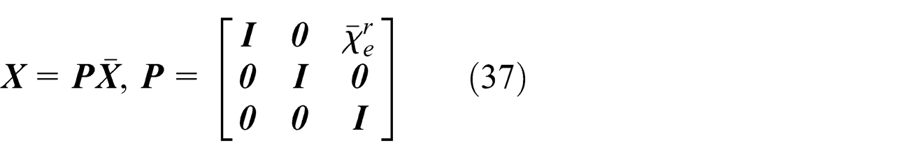
Equations (12) and (13) can be combined and rewritten in a similar first-order form as equation (3); however,
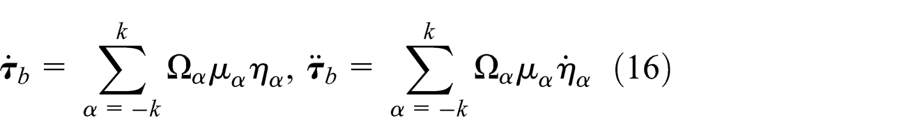
Substituting equation (16) into equations (12) and (13), and using the orthogonality conditions of equation (4), the equations of motion are transferred to

where


An unconstrained gyroelastic body and its ith CMG.
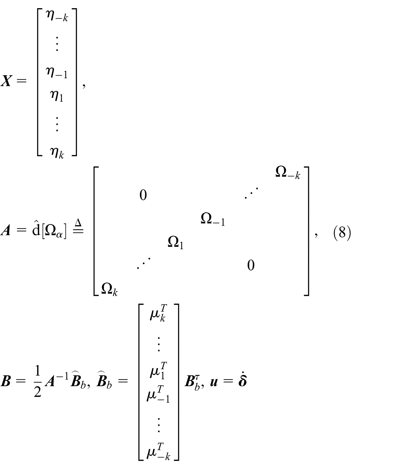
Equation (17) can be succinctly rewritten as

where

The system given by equation (19) has 6 + 2k natural modes, among which there are 6 rigid modes (pseudorigid modes
2
might appear under certain conditions) and 2k gyroelastic modes. The

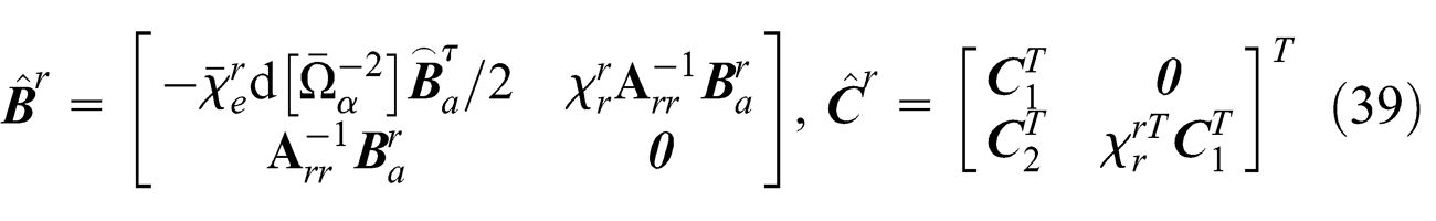
Substituting equation (21) into equation (19) and using the orthogonality conditions in equation (4) lead to

where
It should be noted that
where

where

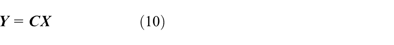
For the observation equation, the outputs are chosen as the inertial angular velocities of the mounting locations. It is evident that they are composed of two parts, the rigid rotation and the elastic rotation caused by the elastic deformation. The rigid rotation is given by
where

where

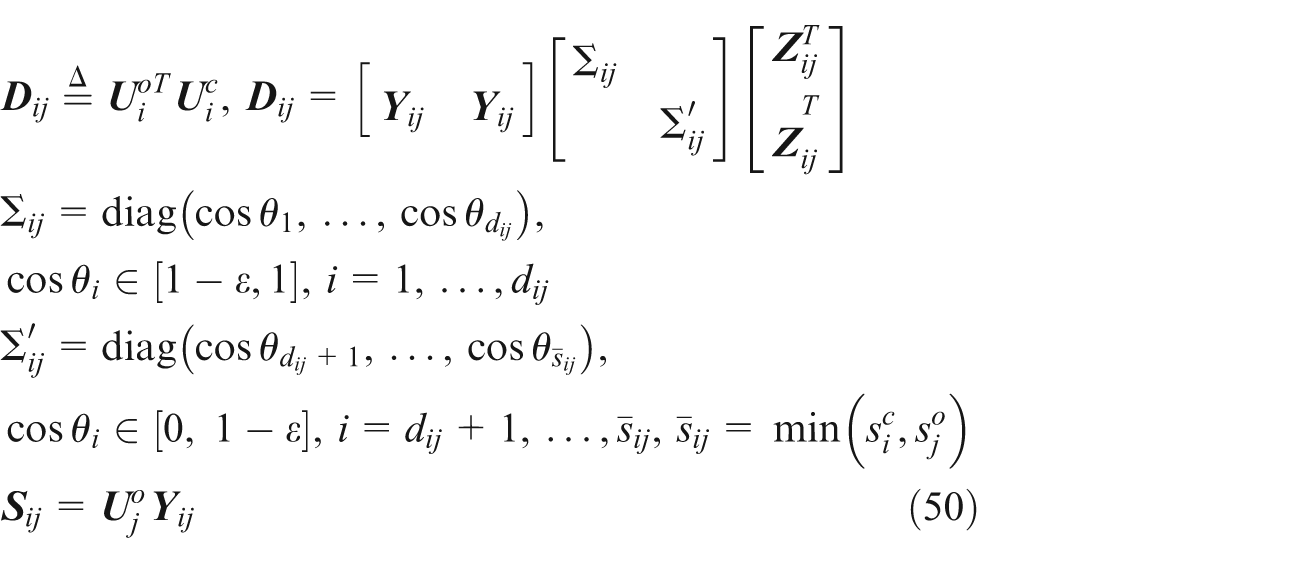
where
The linearized equations of motion of both constrained and unconstrained gyroelastic bodies have been transferred to a loosely coupled state-space form. These equations form the basis for the optimization of the placement of the CMGs and angular rate sensors.
Optimization approaches
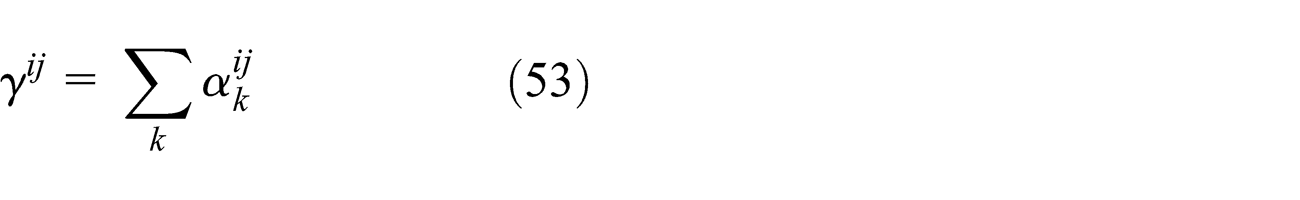
In this section, two controllability and observability indexes are formulated to determine the locations for actuator–sensor pairs. The first index is based on the system controllability and observability matrices, while the second is based on the controllable and observable subspaces of the actuator–sensor pairs.
Controllability and observability matrices method
The constrained gyroelastic body is discussed first. Considering the relation

Substituting equation (8) for

where
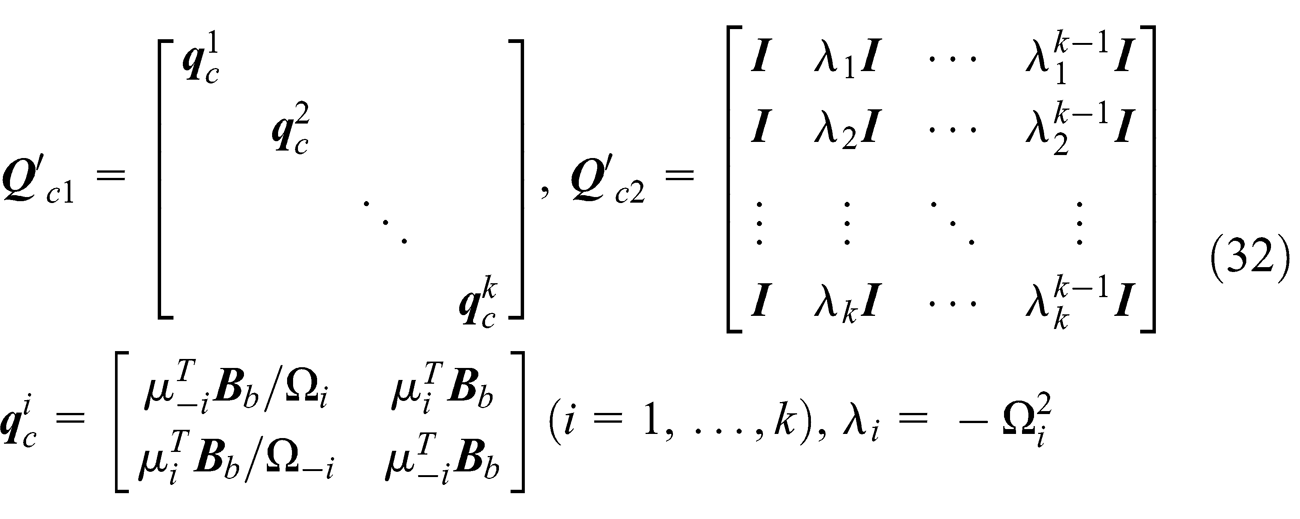
The determinant of

Therefore, it requires

Analogously, the modal observability performance index is defined as
where

Let us now move on to the unconstrained gyroelastic body. The state matrix in equation (26) indicates that the rigid part of the state vector is coupled with the modal coordinates
Noting the controllability and observability of system

It can be seen that the controllability and observability of the rigid coordinates
The controllability and observability of

Because of the form of

where

After calculating
With these developments in hand, the controllability and observability matrices method can be summarized as follows:
Choose the candidate locations for the collocated actuators (CMGs) and sensors (angular rate sensors) on the flexible structure. Suppose there are S candidate locations. Assume only one actuator–sensor pair is mounted at the sth candidate location. Denote the resultant system by Bs ;
Obtain the state-space model of the Bs by the formulations in section “Linearized dynamics and state-space model.” If the system is constrained, equations (7) and (10) are obtained. When the flexible structure is unconstrained, we will arrive at equations (25) and (29);
Calculate the
Select a set of locations with largest
Controllable and observable subspaces method
In this section, a placement procedure for actuators–sensors based on the system controllable and observable subspaces 18 is briefly described. This method can be applied to both the constrained and unconstrained gyroelastic bodies with collocated or noncollocated CMGs and angular rate sensors.
Suppose nc
-specific locations on

where

where
Similarly, the observable states of the jth sensor,
where
where
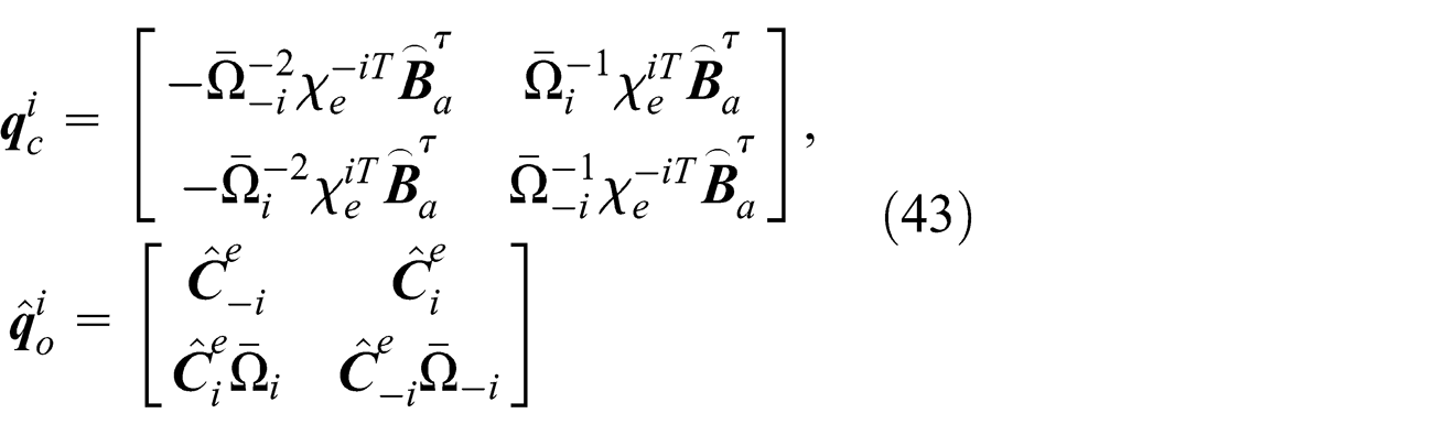
The subspace of both controllable and observable states for the actuator–sensor pair (i, j) is given by the intersection of the range space of

The dimension of
It is obvious that

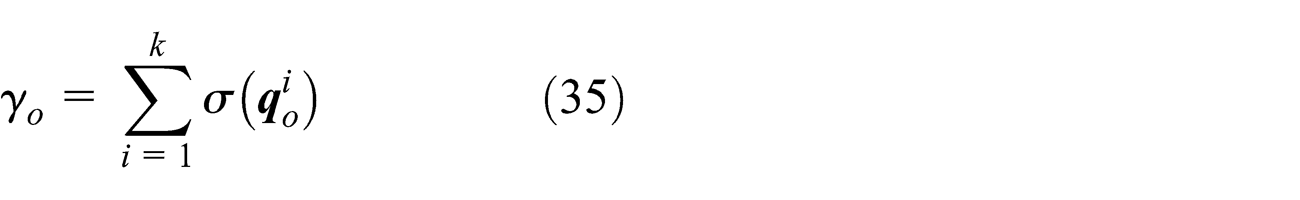
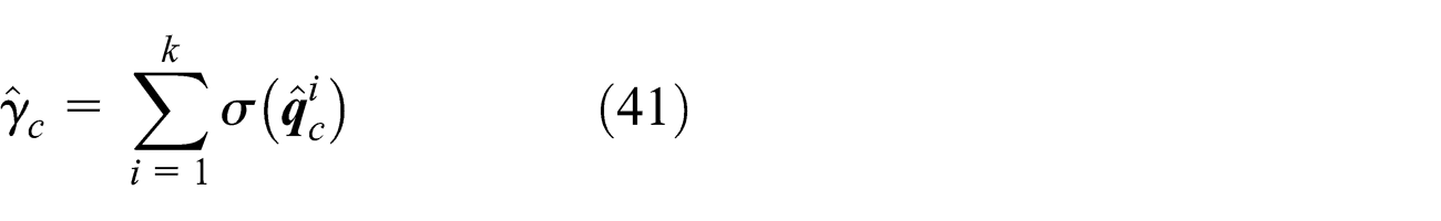
The degree of controllability and observability is determined by the following combined index as

It represents the ability of the pair (i, j) to control and observe the kth system mode. The total ability of the pair (i, j) can be defined as
Therefore, the problem reduces to find a set of (i, j) that give a maximum value of
Now, we can summarize the controllable and observable subspaces method as
Choose nc candidate locations for the CMGs and no locations for the angular rate sensors on the flexible structure, where nc and no could be the same. Assume that all the candidate locations are equipped with the CMGs and angular rate sensors. Denote the resultant system by BS ;
Establish the dynamic model of the BS in state-space form by the formulations in section “Linearized dynamics and state-space model.” If the system is constrained, equations (7) and (10) are obtained. When the boundary condition of the flexible structure is free-flying, we will arrive at equations (25) and (29);
Calculate the index
Select a set of locations with largest
Numerical example
In this section, the placement optimization of actuators–sensors for a cantilevered gyroelastic beam and an unconstrained gyroelastic plate are demonstrated. The simulations are based on a Windows PC using the MATLAB software.
As shown in Figure 3, a constrained gyroelastic beam is discretized as 20 beam elements through the finite element method. The fundamental frequency of the beam structure is 0.025 Hz. The first 20 gyroelastic modes are retained for this system. All the nodes are chosen as the candidate locations for the CMGs and angular rate sensors. The CMGs’ rotors are assumed to have the same angular momentum hi
, while the directions of hi
are all along

A constrained gyroelastic beam (discretized as 20 beam elements) and its cross section.
It is worth noting that two different cases of the initial orientations of the gimbal axes of the CMGs are considered. “Case 1” is that the initial orientations of the gimbal axes are all in the direction of
The two approaches developed above are both applied to the placement optimization of the CMGs and sensors for the gyroelastic beam. For convenience, we call the controllability and observability matrices method as “Approach I,” whereas the controllable and observable subspaces method is named as “Approach II.” For the constrained beam example, the central processing unit (CPU) times of Approaches I and II are 0.46 and 0.45 s, respectively.
Figures 4 and 5 show the results of Approach I for the constrained gyroelastic beam with hi
= 0.1 and 1 N m s, respectively. It can be seen that the optimal locations appear near the free edge of the beam. Figures 6 and 7 demonstrate the results of Approach II—

Controllability index

Controllability index

Controllability and observability index
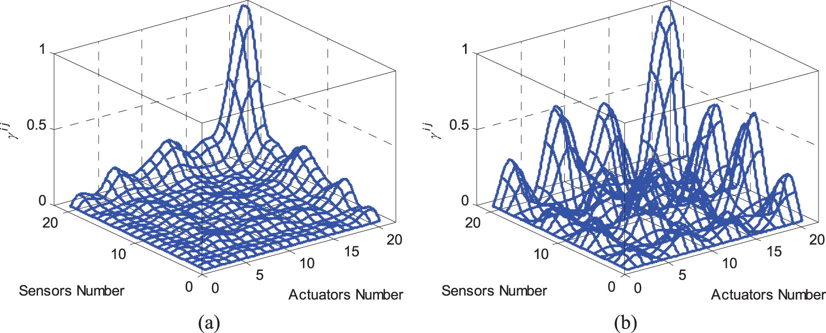
Controllability and observability index
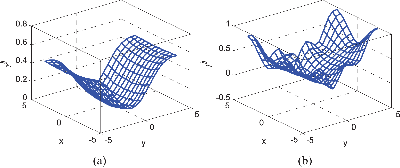
In order to compare the results of Approaches I and II, we define

The difference between

Comparison between the two optimization methods (gyroelastic beam). γii , γco – the controllability and observability index of the collocated CMG and sensor at the node i, calculated by equations (53) and (54), respectively; Δγ = |γco –γii |.
An unconstrained gyroelastic plate (Figure 9) is also considered. A total of 273 candidate locations are selected for the CMGs and angular rate sensors. We only consider the case that all the gimbal axes’ initial directions are along
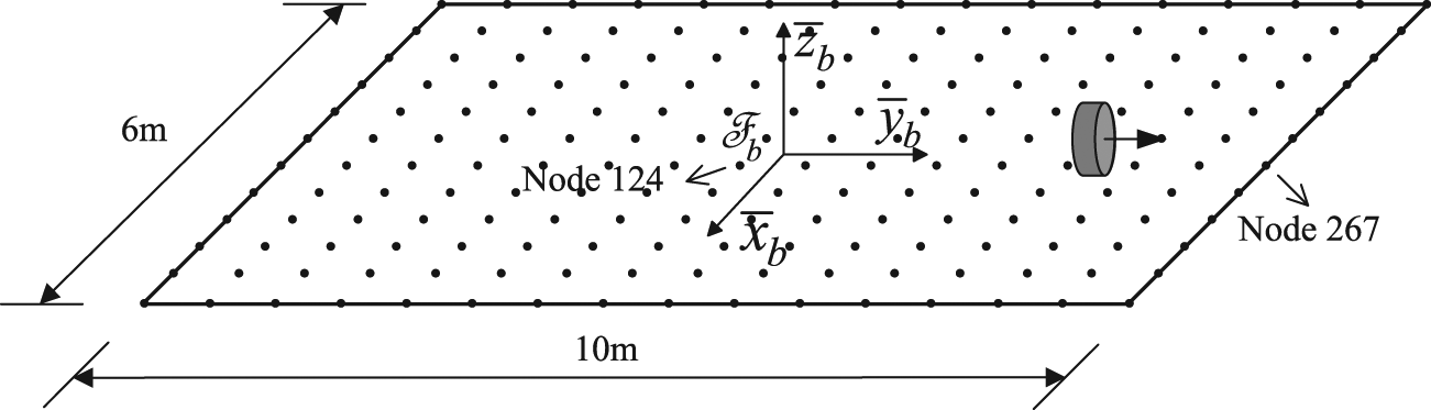
Candidate locations for actuators and sensors on an unconstrained gyroelastic plate.

(a) Controllability index
When applying Approach II, all the candidate locations are supposed to be mounted with CMGs and angular rate sensors (Figure 11). The total amount of the angular momentum on the plate is arranged to be zero to make the plate exhibit the typical pseudorigid modes of the gyroelastic body. The optimization results of gyroelastic plate with nonzero total angular momentum are similar with those of the system in Figure 11. Two reference nodes numbered 124 and 267 are indicated by the arrows in Figure 9. Figure 12 shows

An unconstrained gyroelastic plate with zero total angular momentum.

Controllability and observability index

The computational cost for the placement optimization of the CMGs and angular rate sensors for the unconstrained plate is Approach I = 1.20 s and Approach II = 23.55 s. A comparison is also made for the optimization results. The distributions of

Comparison between the two optimization methods (gyroelastic plate): (a) the distribution of
Conclusion
The placement optimization for the CMGs and angular rate sensors for gyroelastic body is investigated. The linearized equations of motion of the constrained and unconstrained gyroelastic bodies are developed and transformed to a state-space representation. Two optimization indexes are derived from the perspective of controllability and observability. The first is developed through analyzing the rank of the controllability and observability matrices. By the use of the dynamic characteristic of the gyroelastic body, it is proved that the rank of the controllability and observability matrices is determined by the rank of a set of two-dimensional matrices, so the required computational cost is reduced. The second criterion measures the ability of the actuator–sensor pairs to control and observe the system modes. The numerical examples of a constrained gyroelastic beam and an unconstrained gyroelastic plate are given. Both optimization approaches show that the optimal placements for the actuators and sensors are located at the edges and corners of the structure. It should be noted that the proposed methods can be used in complicated gyroelastic systems with arbitrary shape and topology.
Footnotes
Appendix 1
Academic Editor: Xiaotun Qiu
Declaration of conflicting interests
The authors declare that there is no conflict of interests regarding the publication of this article.
Funding
This article reports work carried out in the project supported by the National Natural Science Foundation of China (11272027).