
Abstract
In order to study the torque-induced bending deformation in ball screw systems with uncertain-but-bounded parameters, uncertainty analysis of torque-induced bending deformations in ball screw systems based on an numerical method combined second-order Taylor series expansion with difference of convex functions algorithm is conducted in this research. The maximum torque-induced bending deformation in ball screw systems with certain parameters is solved by modeling the ball screw as a simple Euler–Bernoulli beam. On the basis of the model, the general expression of maximum deformation of ball screw systems in terms of uncertain parameters is derived based on the second-order Taylor series expansion. Then the problem of determining bounds of the maximum deformation of uncertain systems is transformed into a series of box constrained quadratic programming problems. Box constrained quadratic programming problems are solved by difference of convex functions algorithm. The effectiveness of the analysis is validated by Monte Carlo simulation method. Through demonstration, the conclusion can be drawn that the torque-induced bending deformation in ball screw systems with uncertain-but-bounded parameters can be analyzed explicitly by the numerical method combined second-order Taylor series expansion with difference of convex functions algorithm, which offers a new approach for estimating the torque-induced bending deformation in ball screw systems.
Keywords
Introduction
As an important force and motion transfer device, ball screw mechanism (BSM) has the capability of converting rotation into linear motion, or vice versa. It is widely applied to machine tools, robots, measuring instruments, and automatic equipment for its advantages of precise positioning and high efficiency. 1 However, the deformations and vibrations of the ball screw drive components adversely affect the positioning accuracy and fatigue life of the drive. 2
Many works have been conducted on the deformations of the ball screw drive components. Zhang and Sun 3 simplified the screw as a Timoshenko beam, and the screw–nut interface is simulated by the stiffness and damp in six directions considering the effects of pretension, shear, and moment of inertia on the axial, lateral, and torsional vibration. Zaeh et al. 4 established a finite element model of ball screw drive systems considering the lateral deformation of the ball screw, but both the models used for the screw–nut interface stiffness matrix fail to capture the coupling between the axial, torsional, and lateral dynamics of ball screw drives. Okwudire and colleagues5,6 demonstrated theoretically and experimentally that the nut introduces a coupling between the dynamics in the axial/torsional directions and the lateral (bending) direction in BSM. Torque-induced bending deformations were optimized to minimize the static coupling between the applied torque and lateral deformations of the screw in Okwudire. 7 However, from the survey in ball screw manufacturers, the authors found that the preload of the ball screws always depends on the experiences of workers. What is more, wear will occur in the ball screw in the course of service. The preload will degrade gradually. The uncertainty of preload breeds the uncertainty of axial stiffness. The wear and preload degradation result in change in the contact position, which gives rise to the uncertainty of contact angle. But there are few researches on uncertainty analysis of torque-induced bending deformations in ball screw systems.
Uncertainty analysis of torque-induced bending deformations in ball screw systems based on a numerical method combined second-order Taylor series expansion with difference of convex functions algorithm (DCA) is conducted in this research. The maximum torque-induced bending deformation in ball screw systems with certain parameters is solved by modeling the ball screw as a simple Euler–Bernoulli beam. On the basis of the model, the general expression of maximum deformation of ball screw systems in terms of uncertain parameters is derived based on the second-order Taylor series expansion. The problem of determining bounds of the maximum deformation of uncertain systems is transformed into a series of box constrained quadratic programming (QB) problems. The problems are solved by DCA. The effectiveness of the analysis is validated by Monte Carlo simulation (MCS) method. The bounds of torque-induced bending deformations in a certain ball screw system are discussed in this article as well.
Maximum torque-induced bending deformation in ball screw systems
A detailed model for maximum torque-induced bending deformation in ball screw systems is presented in Okwudire. 7 The result is a dimensionless displacement in lateral direction. This section summarizes the derivation of the maximum torque-induced bending deformation in ball screw systems to provide the reader with some context needed for the rest of the article.
Screw–nut interface stiffness model
Screw–nut interface stiffness modeling is the key problem in deformation analysis of ball screw systems. Therefore, screw–nut interface stiffness model should be established to obtain the accurate model of ball screw systems.
Axial preload is usually applied to two nuts in the ball screw by inserting a shim between them. Thus, balls contacting with the two nuts have different contact status, one is L-configuration and the other is U-configuration, which is depicted in Figure 1.

Schematic diagram of preload in ball screw.
In the process of screw–nut interface stiffness modeling, the mass of balls is neglected. The contact stiffness is considered as

Simplification of balls.
In order to convert the contact stiffness of balls to the screw–nut interface stiffness, two steps are conducted. First, the contact stiffness of balls is converted to the global coordinate. Second, the stiffness of a single ball obtained by the first step is accumulated into the screw–nut interface stiffness. Detail solution process is listed as follows.
Contact stiffness conversion of a single ball
According to the geometrical relationship of the ball screws, equation (1) can be obtained

where
Two local coordinates CS1L and CS2L are established as shown in Figure 3. CS1U and CS2U are also established in the similar way. Where the z-axis of CS1L (CS1U ) coordinate points along the contact direction, and the z-axis of CS2L (CS2U ) coordinate (global coordinate) points along the axial direction of the ball screw shaft. The subscripts L and U represent different contact conditions.
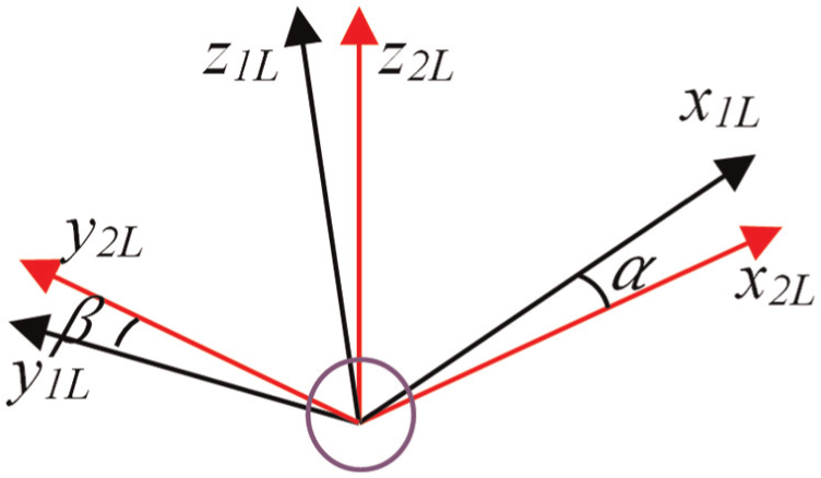
Schematic diagram of local coordinates in L-configuration.
Taking L-configuration, for example,

where

Similarly, for balls on the U-configuration,

CS3 coordinate is established with its z-axis parallel to the axial direction of the ball screw shaft. Its origin is located at the center of each ball. Its orientation depends on the azimuth angle
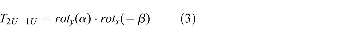
The transformation matrix

Therefore, the transformation matrix

The matrix above is orthogonal, so the inverse matrix
Accumulation of the contact stiffness of balls
CS coordinate is established by considering the center of mass of nuts, which is marked as P, as its origin. Z-axis of the coordinate is along the axial direction of the ball screw shafts. The position of each ball could be represented as


Vector diagram of balls in L-configuration.
where
The contact point between the ball screw shaft and the ball is marked as

where


According to the theory in Okwudire and Altintas, 5 the relationship below can be obtained

where
The function

The axial stiffness of the screw–nut interface can be expressed as follows 8

where
The contact stiffness of the balls is

where
The stiffness between

The displacement of


A matrix composed by the transformation matrix of the nut and the ball screw is

Contribution of each ball to the stiffness of the screw–nut interface is
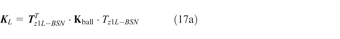
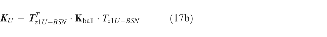
The stiffness of the screw–nut interface can be accumulated as follows

where

Maximum torque-induced bending deformation in ball screw systems
From the stiffness of the screw–nut interface obtained in section “Screw–nut interface stiffness model,” the conclusion can be drawn that deformation not only in torsional direction but also in axial and bending direction occurs when a torque is applied to one end of the screw shaft.
In this research, the situation is considered that the nut has one loaded circuit. This means that all the balls have the same entry and exit angles. Consequently,
The number of balls per unit angular rotation can be expressed as

From the coupling stiffness matrix obtained in section “Screw–nut interface stiffness model,” the third and sixth rows of equation (19) are linearly dependent; the sixth row is equal to the third row scaled by a factor of −
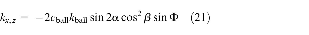
And

In this research, ball screw system is modeled as a simple Euler–Bernoulli beam as shown in Figure 5.

Model of ball screw systems.
In this model, the stiffness of bearings is considered much larger than that of others, and the ball screw is simplified as simply supported beam. The distance between the nut and the left end of the screw is
There is no coupling stiffness between y-direction and θy -direction. Therefore, the deformation in the two directions is ignored. The equilibrium of node at the position of the nut can be described as

where
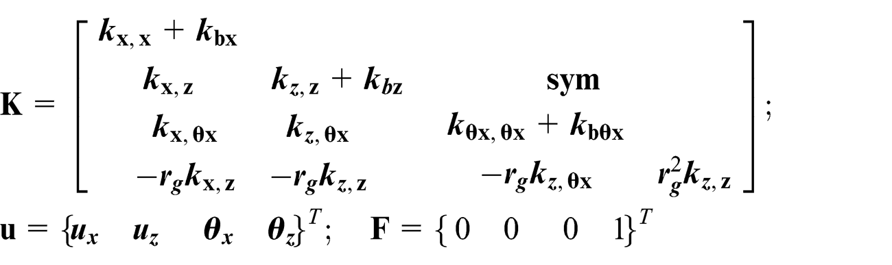
In the stiffness matrix,


where E, A, and I are the elastic modulus of the material, cross-sectional area of the ball screw shaft, and moment of inertia, respectively.
The relationship between maximum bending deformation of the system (
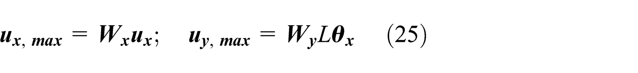
where
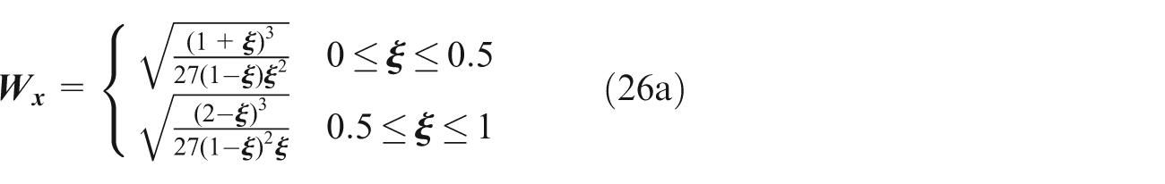

Dimensionless maximum bending deformation of the system among different nut positions is defined as

Uncertainty analysis of torque-induced bending deformations in ball screw systems
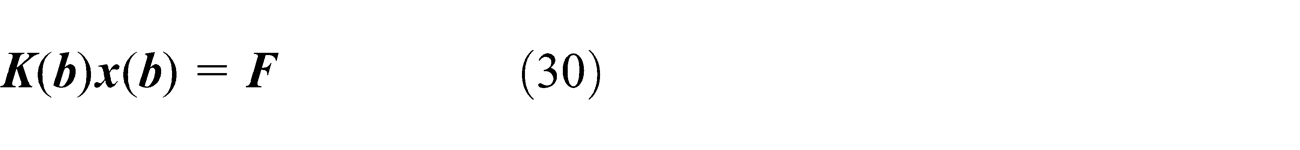
Based on the model in section “Maximum torque-induced bending deformation in ball screw systems,” the stiffness matrix

The parameters of
where
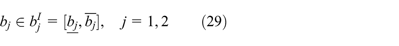
As the uncertainties in

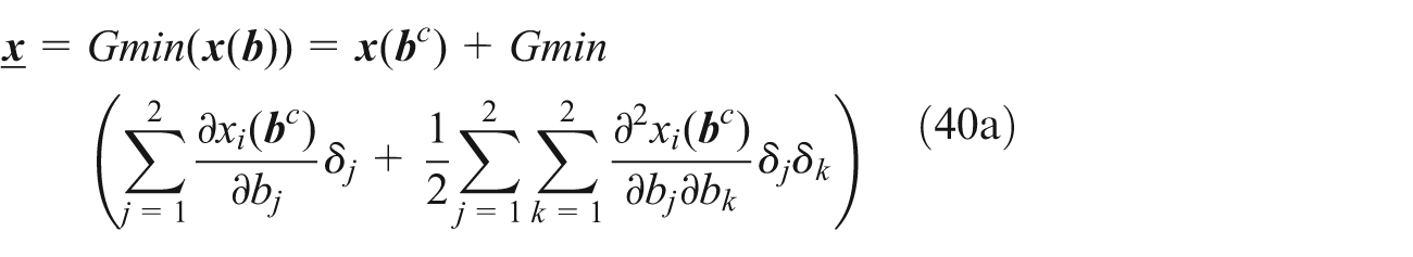
Thus, the deformation


and
Based on interval mathematics, the nominal value vector of the interval parameter vector

where

where
where

where

Differentiating both sides of equation (36) with respect to

Equation (37) can be rewritten as
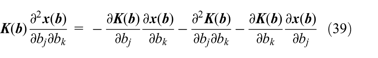
Substituting
When considering the static response analysis of ball screw systems with interval parameters, the primary interest lies in the bounds of the response. Making use of optimization method, from equation (36), the lower and upper bounds of the static response (30) can be determined as follows

The optimization problems can be transformed into the following QB problems

where
The elements of
DCA proposed by Tao and Souad 12 is a continuous optimization approach based on the duality for solving programming in a general form of difference of convex functions, and the DCA only requires matrix-vector products. For the QB problems (41), the DCA converges to a global optimal solution in polynomial time.
DCA for the QB problems or problems (41) is well established and described in detail in the literature. 11 The QB problem can be written in the following form

where
The circumscribed ball of design region of the ball constrained quadratic programming (QBA) problem can be described by
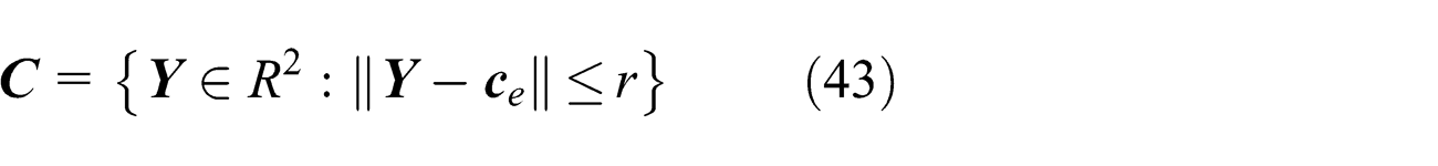
where

where
By solving the QB problems (41) based on the DCA for QB problems, we obtained


where
Validation
In order to validate the effectiveness of the analysis, MCS method is conducted and compared with the method in this article.
Case 1. A lead of 20 mm is used for the simulations. This corresponds to
Case 2. A lead of 5 mm is used for the simulations. This corresponds to
Both the two cases have the same uncertainty.
Comparison among different methods for Case 1.

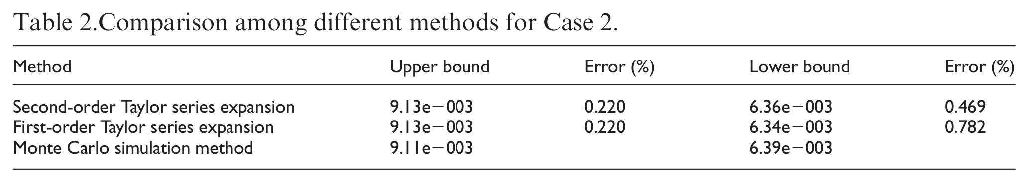
Comparison among different methods for Case 2.
MCS method is the numerical method for estimating the upper and lower bounds in a box region
From the comparison with MCS method in Tables 1 and 2, the errors of the two methods are relatively small, and the result of second-order Taylor series expansion is more accurate than that of first-order Taylor series expansion. The method in this research can be employed to conduct the uncertainty analysis of torque-induced bending deformation in ball screw systems.
Results and discussions
Detail uncertainty analysis for the two cases above is conducted. From the bounds of the maximum torque-induced bending deformations in ball screw systems depicted in Figure 6, the conclusion can be drawn that the upper and lower bounds of maximum deformation of ball screw systems studied in this article are approximately proportional to the uncertain factor

Bounds of the maximum torque-induced bending deformations in ball screw systems: (a) Case 1 (
From the comparison in Figure 6, the larger the uncertain factors, the larger the errors between the results of second-order Taylor series expansion and that of first-order Taylor series expansion. Therefore, much larger error will be introduced if first-order Taylor series expansion is applied to analyze the bounds of the maximum deformation in ball screw systems.
According to the uncertain analysis for the two cases in Figure 6, the conclusion can be drawn that the bound of torque-induced bending deformations in ball screw systems can be obtained via second-order Taylor series expansion. If the uncertainty of
Conclusion
The following conclusions can be drawn from the uncertainty analysis of torque-induced bending deformations in ball screw systems based on an numerical method combined second-order Taylor series expansion with DCA:
For ball screw system studied in this article, the upper and lower bounds of maximum deformation of ball screw systems are approximately proportional to the uncertain factor
By comparison among the results obtained by second-order Taylor series expansion, first-order Taylor series expansion, and MCS, it is concluded that second-order Taylor series expansion has high precision in predicting the bounds of the maximum torque-induced bending deformations in ball screw systems. Uncertain analysis of maximum deformation in ball screw systems can be conducted by the method combining second-order Taylor series expansion with DCA, which provides a new approach for estimating the maximum torque-induced bending deformations in ball screw systems.
Footnotes
Acknowledgements
The authors are grateful to other participants of the projects for their cooperation.
Academic Editor: Rahmi Guclu
Declaration of conflicting interests
The authors declare that there is no conflict of interests regarding the publication of this article.
Funding
This work was supported by National Natural Science Foundation of China, Grant No. 51105010; Natural Science Foundation of Beijing, Grant Nos. KZ201410005010, 3122005 and 3154029; Important National Science & Technology Specific Projects of China, Grant No. 2012ZX04010021-001-004; and Startup Project of Doctor Scientific Research of Beijing University of Technology.