
Abstract
The position and inclination of the mooring legs and yoke of a soft yoke mooring system for floating production storage and offloading in Bohai Bay were measured by full-scale monitoring technique. A novel multi-body dynamic analytical method of the horizontal restoring force for the soft yoke mooring system was established and investigated based on the monitoring data. The result predicted by the dynamic method agrees well with that obtained by fibre Bragg grating strain sensors. The peak value determined by the dynamic analysis is approximately 25% higher than that of the static results in harsh environments, which indicates the high reliability of the proposed method. After significant monitoring time, the advantages of the stability of the measurement by the proposed method are also manifested.
Introduction
Due to the discovery of oil and gas in China Bohai Bay, using single-point mooring floating production storage and offloading (FPSO), mining with wellhead platforms and offloading operations has become a cost-effective exploration model. The restoring force performance cannot use its gravity-based restoring force design because of the shallow water in Bohai Bay. Moreover, significant nonlinearity between the restoring force and the FPSO displacement in catenary mooring systems is also observed. Therefore, gravity-based tower soft yoke mooring systems (SYMs) are commonly used for six FPSOs in Bohai Bay. 1 Although there are diverse forms of mooring structures, the basic design process of the structures is almost the same as follows: first, it enhances the potential energy of ballast to change the stiffness of mooring system by lifting ballasts; second, it could fix a position for the tanker in a certain sea area under complex working conditions. In this case, the positioning technology is a stiffness relationship between restoring force and displacement, compared with soft connection (hawser) and rigid connection (fixed yoke); the positioning technology of SYM has a bumper characteristic so that it could reduce the impact force of tower platform. Finally, the SYM has a function of weathervane effect which makes tanker effectively reduce environment loads and improve its survivability in extreme weather conditions.
The mooring system of an FPSO is the key facility for the development of offshore oil and gas. Much attention should be paid to this system because the load effect of shallow water on a FPSO may cause significant property loss and serious environmental pollution. In recent years, several accidents involving mooring structural damage have occurred due to underestimated environmental loads and unreasonable structural design. For example, in November 2009, ‘CNOOC 113’ FPSO, which has an oil storage capacity of 160,000 m3 and is located in the BZ25-1 oil field at a water depth of approximately 17.4 m, underwent damage to its mooring system and pulled down a single-point tower due to harsh environmental loads and nearly collided with nearby jacket production platforms. In April 2011, the SYM of the ‘CNOOC 102’ FPSO was similarly damaged after being in service for 22 years and caused oil field production to be suspended for 3 months. As energy demands continue to grow, people are pursuing higher safety standards for marine engineering structures. On one hand, a reliable and effective method is required to observe the safety of SYMs under extreme conditions for on-site structures. On the other hand, further study of SYM is required, including the study of SYM mooring capacity under extreme conditions, structural fatigue problems and complex motion response, to evaluate existing structures and provide guidelines for future design.
Currently, research on model and numerical experiments for SYMs in shallow water is still active.2–4 However, due to the complex and uncertain nature of the marine environment and the large scale of marine engineering structures, theoretical calculations and model experiments are limited despite the many efforts undertaken by various scholars to approximate real solutions.5–8 Based on the field monitoring of prototype structures, the motion response of mooring structures and tankers can be obtained directly. This method is extremely important in testing mooring structure designs and in ensuring the safety of marine platforms; furthermore, the method can be used to solve certain problems that cannot be addressed by laboratory-scale experiments and numerical experiments.
In recent years, the field monitoring of floating platforms has been favoured by oil companies and research institutes. Floating structures of deep-water platforms, such as tension leg platform (TLPs), 9 SPARs,10–12 semi-submersible platform (SEMIs), 13 and FPSOs,14–18 have been successfully and widely applied, whereas the monitoring of SYMs in shallow water has seldom been reported. In this study, the method of monitoring SYM in Bohai Bay was carried out. Based on the motion and position data measured for an SYM, an appropriate multi-body dynamic method and corresponding equations were developed. The results provide an efficient means for enriching and improving the information evaluation technology and early warning technology of SYMs. In this respect, the risk control and safety guaranteed for FPSO can be further protected.
Problem description
SYMs are deployed in shallow water at depths below 50 m and consist of a fixed tower; an A-frame yoke with ballast weights, which provides a restoring force; and two pendants or chains connecting the yoke and FPSO, as shown in Figure 1. For two pendants, the working principle of the SYM is listed as follows: X1, X2, X3 and X4 (Table 1) are the four rotational nodes of the mooring system, where X1 is a universal hinge over the mooring leg that can rotate freely without restraint between the FPSO and the mooring structure; X2 and X3 can rotate along two axes (horizontal rolling and vertical rolling); X4 is a turntable on the tower that allows the FPSO to weathervane under environmental stress. For simplification, this study only focused on plane static conditions. The initial state of the mooring system is as shown in Figure 1. X1 and X3 (X4) are the support points of the FPSO and the mooring tower. When winds, waves and currents act on the FPSO, the FPSO is immediately perturbed from its equilibrium position. When the external force is removed, the FPSO returns to the equilibrium position depending on the force of the ballast weight. This force is called the restoring force. The design of the restoring force is an important factor in developing SYMs that should be handled appropriately to ensure operation safety.

Soft yoke mooring system.
Six degrees of freedom in SYM.

SYM: soft yoke mooring system.
The SYM is a highly nonlinear multi-rigid body system. For this reason, it is practically difficult to perform the analysis due to the motion complexity of this type of offshore petroleum equipment. As the FPSO moves, the restoring force depends not only on the tanker’s position but also on the tanker’s velocity, and the various components of the velocity of the SYM also affect the tanker’s movement. According to the relevant principles of marine engineering design, it is a common practice to solve for the horizontal restoring force of SYM using a static analysis method. 19 However, the effect of the structural inertial force in real motion is neglected in the static method because of the large mass of the structure, which cannot ensure the accuracy of the calculation results. Thus, it is necessary for operators to obtain the response of the mooring loads of a mooring structure under harsh environmental conditions.
In this article, the position of a mooring structure and the load measurement of a field monitoring system were established, taking an on-site FPSO with an SYM in Bohai Bay as an example. The inclination of the mooring leg and the yoke was obtained in real-time. Using the method of multi-body dynamics, the horizontal restoring force of this type of SYM was solved for, and, using fibre Bragg grating (FBG) strain sensors to measure the restoring force in the field, the dynamic methods were compared. Furthermore, in order to facilitate this study, a full-scale measurement system for the SYM was also carried out for a 56KDWT FPSO in Bohai Bay, with details shown in Table 2. The total monitoring system is composed of three sub-monitoring systems, including an environmental factor monitoring system, a hull and mooring structure position monitoring system and a restoring force monitoring system, which contains the inclinometers and FBG strain sensors. The monitoring information of each sensor was displayed by integrated display software by an independently developed data collector. The sensor layout scheme of the SYM on-site monitoring system is shown in Figure 2. The on-site monitoring system and main sensors together with the main parameters of the SYM are listed in Table 3.
Main particulars of 56KDWT FPSO.

mld: moulded; FPSO: floating production storage and offloading.

Sensor layout scheme of the on-site monitoring system.
On-site monitoring system and main sensors.

FPSO: floating production storage and offloading; FBG: fibre Bragg grating.
Analysis of the horizontal restoring force by the static method
For the horizontal restoring force of the SYM, static calculation is usually used to analyse the mooring system’s static behaviour and the static restoring force index. Taking the on-site FPSO discussed above as an example, it is assumed that the system is static, and the SYM satisfies the force and moment equilibria in both the longitudinal and vertical motions. The forces of the SYM in the horizontal and vertical displacement directions are shown in Figure 3.

Static and dynamic analyses of the SYM.
In Figure 3, two equations for the relationship between the distance and inclination can be established according to the constant length of the yoke and mooring legs

where
The main parameters of the SYM.

According to the equilibrium relationship, the following can be obtained

According to the moment equilibrium principle, the left and right sides of O reach the following equilibrium states
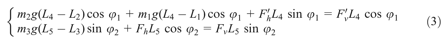
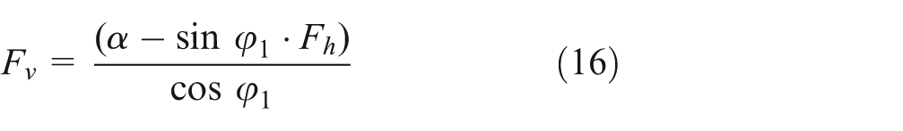
Based on the three equations described above, the horizontal restoring force of the SYM can be written as follows

The real-time inclinations measured by inclinometers are substituted into the static equation of the SYM, and the static horizontal restoring force of the mooring system can be solved using MATLAB programming.
Analysis of the horizontal restoring force by the dynamic method
In consideration of the dynamic characteristics of the mooring structure’s motion, the dynamic analysis from multi-body system perspective could be performed because the SYM is composed of the substructure as previously mentioned. Of the various dynamic methods that exist, the Kane method takes generalised velocities as the independent variables, and each particle velocity in the system is uniquely represented as a linear combination of the generalised velocities. The SYM conforms to the conditions of a multi-body system; thus, the Kane method can be used for its dynamic calculation. In fact, the SYM only provides the restoring force on the surge motion and there are no constraints for other motions; it can be described for the surge motion of the tanker in plane, as shown in Figure 3. In the prototype structure, it is feasible to measure the two angles
As shown in Figure 3, the generalised velocities

The generalised velocity constraints are generated by both sides of the derived equations

where
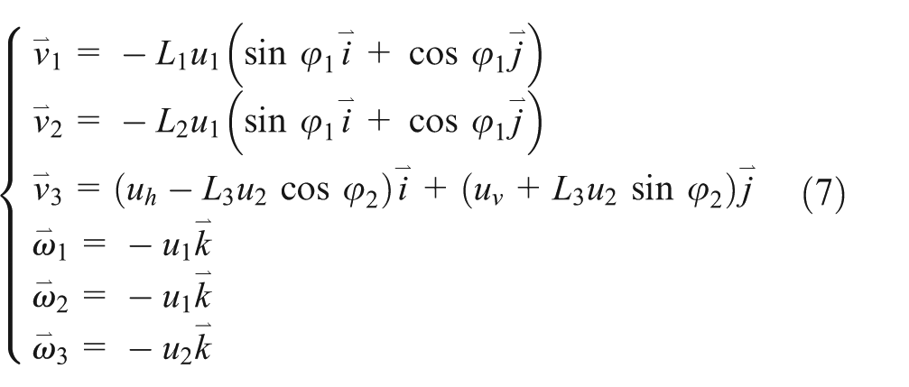
Dividing each equation by
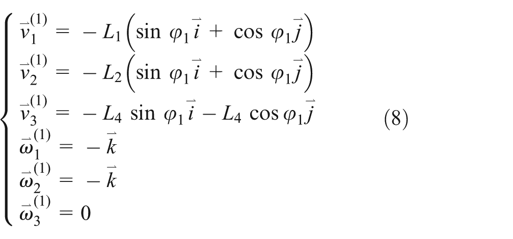
The partial velocity and the angular velocity corresponding to
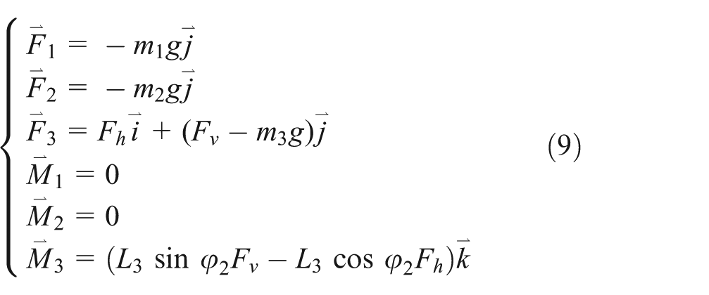
As the dynamic method is chiefly concerned with inertial force of structure, the inertial force is

The dynamical system of equations is

The following can be substituted into the equilibrium equation

Thus, the horizontal restoring force


The horizontal restoring force and the vertical restoring force can be described as follows

As in equation (6),

Based on the position information of the SYM measured by field monitoring in real-time, the angle, angular velocity and angular acceleration of each part of the mooring structure can be obtained. Substituting these parameters into the dynamic equation and using MATLAB for calculation, the dynamic horizontal restoring force of the mooring system can be determined.
Analysis of the dynamic characteristics in field measurements
Once the inclination of the mooring leg and the yoke is determined, the position of the SYM can be obtained, so that the influence of roll, pitch, heave and surge FPSO movements on restoring force has been fully considered by dynamic method. During monitoring, based on the range of values over which the position of the SYM varies in the basin model experiment, the range and accuracy of the position-measuring equipment in field-based prototype measurements are determined. 5 Two groups of inclinometers are arranged on the left and right sides of the yoke; the other two groups are installed at the upper end of the mooring legs in order to reduce the effects of the sway of the mooring structure. The measurement range of the position inclinometer installed on the mooring leg is ±90°, and the measurement range of the position inclinometer installed on the yoke is ±30°. The theoretical curves of the inclinometers are shown in Figure 4. It should be noted that as the height of X1 hinge point (Figure 1) is changed due to fully loaded or ballasted FPSO in the mean sea level (MSL), the inclinations of the yoke and the mooring leg could also be changed slightly. The data of four inclinometers were transmitted into the computer in central control room via lineate transmission and measured at a frequency of 1 Hz.

The inclinations of the mooring structure excursed from the neutral position in the MSL.
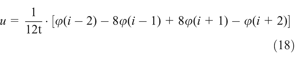
Based on the position response of the mooring leg and the yoke in the prototype measurement, the inclination of SYM could be obtained by inclinometers (Figure 5), whereas the angular velocity and the acceleration of each part of the mooring structure can be obtained using the Runge–Kutta method


Position-measuring sensors installed in the field: (a) inclinometer installation location and (b) inclinometer.
Substituting these values into the dynamic equation based on the Kane method, the dynamic horizontal force of the mooring system can be solved for. Furthermore, to compare with the results of the dynamic method proposed in this article to verify the method’s feasibility and accuracy, the strain measurement method was applied in the field, which is the inclinometers’ redundancy. In recent years, the determination of the structure force by measuring the strain of a structure has been widely applied in civil, water conservancy and aerospace engineering. The primary advantage of this method is that it can obtain the mechanical behaviour of a structure directly by measuring the strain with high accuracy. However, the method also has limitation that FBG technology cannot be steadily applied over the long term for marine engineering equipment structures due to the differences of harsh marine engineering environment and the great temperature between day and night, as well as the strong corrosivity. Moreover, the thermal engineering on mooring structure, such as welding, is always forbidden in the process of producing so that the FBG sensors could only be pasted in some key structures, and it is easy to make the measurement data inaccurate for a long time. As stated above, FBG strain sensors are only suitable for a short-term measurement.
First, three-dimensional finite element analysis of the SYM was carried out using AQWA and ANSYS to determine the sensitive parts of the structure, as shown in Figure 6. The mooring leg can be simplified as a two-bar structure; thus, there was a one-to-one relationship between each mechanical behaviour and the strain of the mooring legs, and the location of the strain measurement was selected finally. Second, after the completion of the FBG sensor calibration in the laboratory (Figure 7), FBG strain sensors were required to be pasted to two mooring legs along the axis, as shown in Figure 8. In order to ensure the accuracy of the measurement, symmetrical arrangement of the four FBG sensors was adopted, respectively, in two mooring legs. Several FBG sensors were adopted for temperature compensation in the bottom of the mooring legs. Finally, each FBG sensor was joined in a series connection at the two mooring legs, and the data measured were stored in the central control room via two channels. Furthermore, the result yielded by the FBG sensor measurements was the axial force of the mooring legs. Calculation of the mooring angle was still required to obtain the horizontal restoring force.
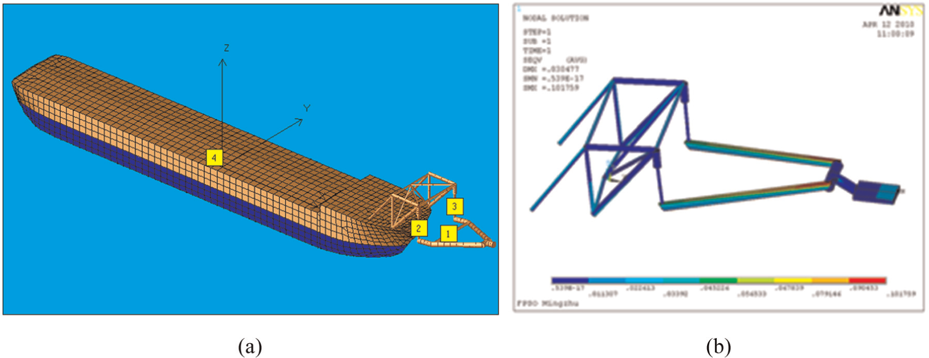
Finite element analysis of the SYM: (a) AQWA and (b) ANSYS.

The strain measurement in the laboratory.

Actual installation location of the fibre grating sensors.
The mooring stiffness contrast
The monitoring system was installed in this FPSO in June 2010, and a large amount of effective data concerning the restoring force have been obtained. Based on the restoring force measured by the FBG sensors in different sea states and the surge displacement of the FPSO, the stiffness curve of the SYM is as shown in Figure 9. The measured result agrees with the theoretical soft yoke mooring stiffness curve, and the accuracy of the data measured by the FBG strain sensors is verified.

Stiffness curve of the SYM.
Comparison of the results obtained from the dynamic method and the FBG sensors
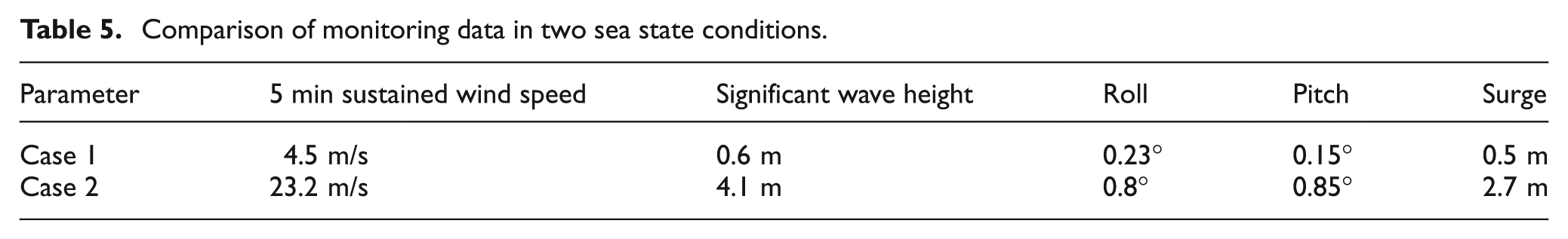
During the monitoring period, the FPSO experienced more than 1-year-return sea state conditions. Table 5 compares the relevant monitoring data of the behaviour of the mooring structure due to winds, waves and currents, where case 1 is in comparatively mild conditions and case 2 is in the more than 5-year-return sea state conditions. Based on the position data of the mooring leg and the yoke determined by the measurement, the horizontal restoring force of the SYM was obtained by the dynamic calculation method, and the horizontal restoring force was also compared with the data measured by the FBG sensors, as shown in Figure 10.
Comparison of monitoring data in two sea state conditions.

Comparison of the restoring forces between the dynamic method and the measurement data.
The FBG sensors reflect the real force of the SYM. Two trends are compared in Figure 10. As indicated in the figures, the results of the dynamic method are consistent with the values measured by the FBG sensors in most cases and are slightly smaller in some cases with little margin of error. This demonstrates the rational of using multi-rigid body dynamics to calculate the horizontal restoring force, as well as the accuracy of the data. Based on the dynamic method, the inclinometer sensors can be applied for the field monitoring of SYM. During field monitoring, a calculation program that executes the dynamic method is embedded into the monitoring software, and the horizontal restoring force on the monitoring interface can be displayed in real-time, which allows operators to check the environmental loads and restoring force to ensure operation safety.
Comparison of the results obtained by dynamic method and the static method
The above figures show that the horizontal restoring force could generally be divided into two components, the low-frequency component and the high-frequency component, which are closely related to the surge motion of the tanker, as shown in Figure 11.

Surge motion displacement and energy frequency in case 2.
In fact, the surge motion of this FPSO is usually dominated by low-frequency motion.20,21 As the tanker moves in low frequency, the inertial force of the SYM is not obvious due to the slow motion although the higher force amplitude is still caused by the low-frequency components. However, the surge motion is also appeared a few part of the high-frequency component that, the dynamic force is obviously higher than the static force in the harsh environments, since the inertial force of the SYM has a demonstrable effect. To prove this point, the results of the dynamic method and the static method are compared.
With regard to the two conditions above, the calculation results of the dynamic method and the static method are also compared, as shown in Figure 12. Figure 12 compares the results obtained by the dynamic method and the static method. Consistent results are observed in case 1 in the mild environment. Such results are obtained because of the mild movement of the SYM and not the prominent dynamic effect. When there are strong winds and waves (case 2), the peak value of the dynamic analysis is approximately 25% higher than that of the static results due to the consideration of the effect of the inertial force of the structure. The restoring forces of low-frequency component and high-frequency component in case 2 are shown in Figure 13.

Comparison of the restoring forces between the dynamic and static methods.
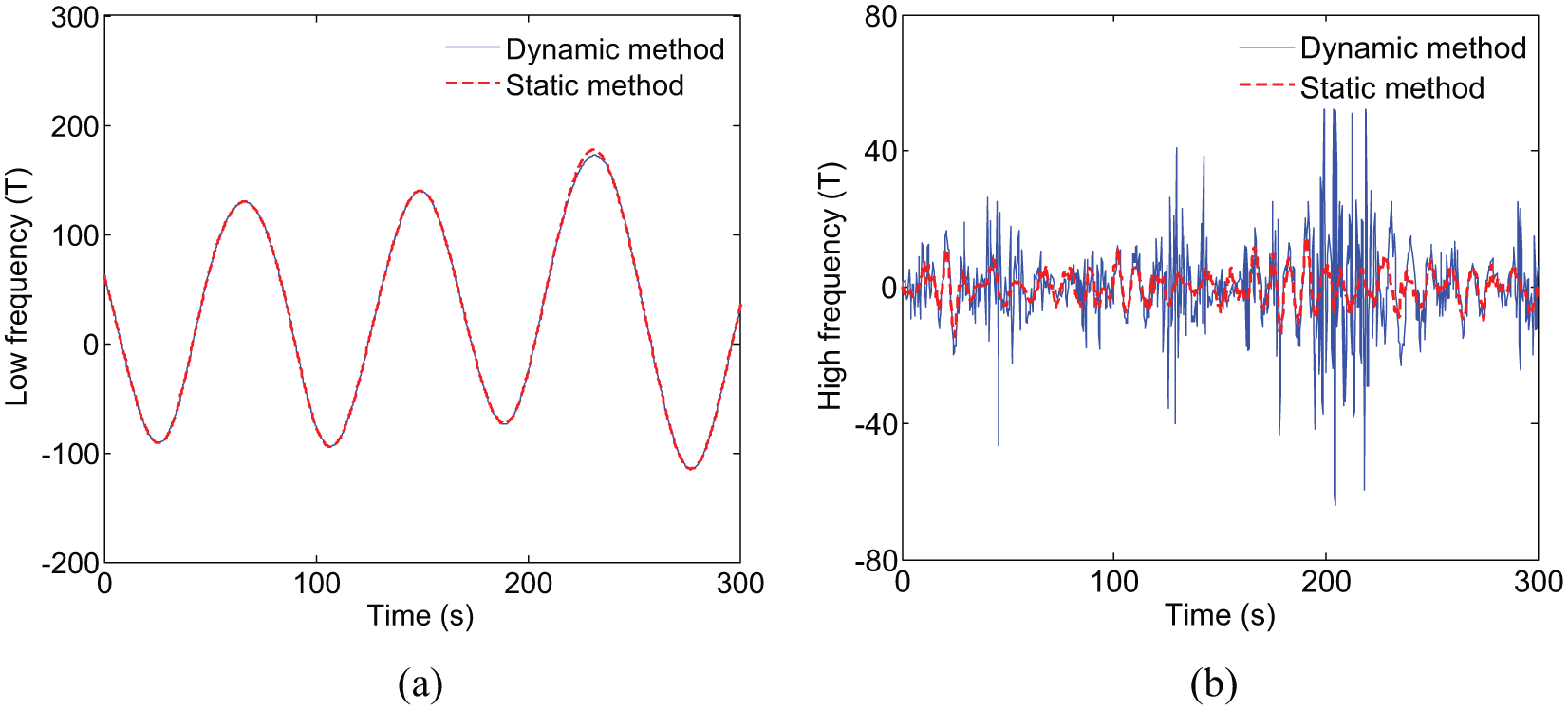
Comparison of the restoring forces between low-frequency component and high-frequency component in case 2: (a) low-frequency component and (b) high-frequency component.
Based on the foregoing discussion, the restoring force determined by the dynamic method is a true reflection of the force acting on the mooring system, and it can help operators ensure the safe operation of the structure for engineering applications. The maximal values of the horizontal restoring force per hour from the inclinometers are identified and long-term characteristics are shown in Figure 14, which indicated that the inclinometers have a long-term stability. Moreover, from the perspective of the monitoring instruments, the inclinometer sensors offer a variety of advantages over FBG strain sensors, such as low unit price, simple field arrangement, low deployment number, great environmental adaptability and convenience of replacement. These advantages help to promote this monitoring method over those implemented on other FPSOs with SYMs in Bohai Bay, which can also provide safety guidelines for future offshore oil and gas production.

The measurement results throughout the year in 2011.
Conclusion
Due to the lack of force measurement devices for SYM on FPSOs in service, strain damage is frequent in harsh sea states. Therefore, a field monitoring system for SYM FPSO was developed in this study, and the movement position and load response were monitored in real-time. Based on the position data of the yoke and mooring legs measured in field, a control equation for the horizontal restoring force was established by adopting a multi-rigid-body dynamic method. The dynamic equation fully considers the dynamic behaviour of the SYM in operation. The multi-rigid-body dynamics calculation method was validated by comparing the data obtained by the dynamic calculation model with the data measured by the FBG sensors. Compared to the results calculated by the static method, the results obtained for the horizontal mooring force using the method proposed in this study are 25% greater in a more than 1-year-return environment. Considering the effects of the dynamic behaviour monitoring system, the proposed method can reflect the real working conditions of FPSO mooring systems. Moreover, a convenient way to guarantee the safety of FPSOs featuring SYMs can also be provided.
Footnotes
Academic Editor: Seiichiro Katsura
Declaration of conflicting interests
The authors declare that there is no conflict of interests regarding the publication of this article.
Funding
This work was supported by the National Science Group of China (grant number 51221961) and the National Key Basic Research (grant number 2011CB013705) and Development Program (grant number 2011ZX05026-002-02).