
Abstract
Based on the proposed end-effector structure of a laparoscopic minimally invasive surgical manipulator, a dimensional optimization method is investigated to enlarge the motion range of the mechanical arm in the specific target area and reduce the collision among the mechanical arms simultaneously. Both the length of the kinematics links and the overall size of the integrated system are considered in the optimization process. The NSGA-II algorithm oriented to the multi-objective optimization is utilized to calculate the Pareto solution set of the objective function. Finally, the dependence of the evaluation indexes is analysed to filter the non-inferior set, which guarantees the selection of the optimization solution.
Introduction
Since Dr Mouret performed the world’s first laparoscopic cholecystectomy in Lyon, France, in 1987, the operative surgery has stepped into the minimally invasive surgery era. 1 Generally, in an open surgery, a large incision is needed to expose the focus area completely. A minimally invasive surgery differs from the open surgery, which only uses several small incisions with a diameter of 5–12 mm on the human body as the laparoscope or the surgical instrument channel. Compared with the open surgery, the minimally invasive surgery can reduce the probability of infection and complications and features many advantages such as small surgical trauma, shorten recover time, and less pain and blood loss. 2 Moreover, the robot technology is introduced to the minimally invasive surgery, which is beneficial to overcome the disadvantages of traditional minimally invasive surgery, for example, bad hand–eye coordination, poor flexibility, easy fatigue and magnified hand tremble.3,4 The robotic minimally invasive surgical system is considered as another milestone in the operative surgery history. 5
Since the minimally invasive surgical robot shows significant clinical value and huge potential economic benefits, the robot-assisted minimally invasive surgery technique has become a hot research issue in the robotics field. 6 The minimally invasive surgical robots developed by many research institutions have achieved great success, such as the ZEUS and the Da Vinci minimally invasive surgery systems approved by US Food and Drug Administration (FDA),7,8 RAVEN series surgical robot system developed by University of Washington9–11 and MiroSurge minimally invasive surgery robotic system developed by DLR. 12
The robot-assisted minimally invasive surgery requires the mechanical arms to realize the coordinated operations such as suturing, knotting and tissue separating in the human body’s closed space. On the other hand, the system is also required to minimize the collisions among the mechanical arms and the interference with other surgical equipment. That is, a large collaborative workspace in the human body and a small interference space outside the human body are two fundamental requirements for a minimally invasive surgical system. Therefore, in order to perform a high-quality minimally invasive surgery, it is very necessary to optimize the structure parameters of the mechanical arm to satisfy the requirements mentioned above. Oriented to the actual laparoscopic minimally invasive surgery, this article proposes a systematic design of the minimally invasive surgical manipulator, in which three independent mechanical arms are arranged in the form of parallel configuration on the same mobile base. This design scheme can enhance the overall flexibility of the system, and it is also helpful to determine the relative position between the manipulators. However, it will also lead to the interference among the mechanical arms. In order to reduce the probability of the collision, this article proposes a NSGA-II-based methodology for the mechanical arms’ optimization. Two performance indexes, that is, the average collision-free inverse solution (NCS) and the target area reachable rate (TAR), are utilized in the multi-objective optimization. Based on the actual conditions, the Pareto solution set is analysed and ranked to determine the optimal structural parameters of the minimally invasive surgical robot.
Design of the minimally invasive surgical manipulator
As shown in Figure 1, the minimally invasive surgical manipulator consists of one laparoscope arm and two instrument arms. The three arms are arranged in form of parallel configuration on the same mobile base. Each mechanical arm contains three parts, that is, the preoperative positioning mechanism, the remote centre of motion (RCM) kinematic mechanism and the end-effectors. The preoperative positioning mechanism enables to adjust the spatial position of the minimally invasive surgical manipulator via four rotational joints and one prismatic joint, which determines the initial position and orientation of the mechanical arms. During the operation, those joints must be locked, and the end-effectors are driven by the RCM kinematic mechanism to perform the operation.

Minimally invasive surgery manipulator.
During the surgical procedure, the additional non-surgical damage on the surgical incisions is intolerable. Therefore, the kinematic mechanism with a fixed spatial pivot point should be proposed, which is free from the control of physical hinges. The concept, that is, the RCM mechanism, was first proposed by Taylor in 1995. 13 The compound parallelogram mechanism is the most common RCM mechanism for the minimally invasive surgical robot design, whose principle is shown in Figure 2. Lever 4 does not exist in the actual structure, and levers 1, 2 and 3 can rotate around the RCM point via the geometrical constraints among the parallelograms A, B and C. Meanwhile, the plane mechanism is driven by a rotating joint whose axis also passes through the RCM point. The compound parallelogram mechanism can guarantee that the movement of the instruments will not cause serious additional damage on the patient incision.
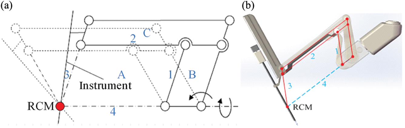
The compound parallelogram mechanism for RCM.
Since the three mechanical arms are identical in structure, the left mechanical arm is discussed as an example to establish the kinematic model. The D-H coordinate system is shown in Figure 3.
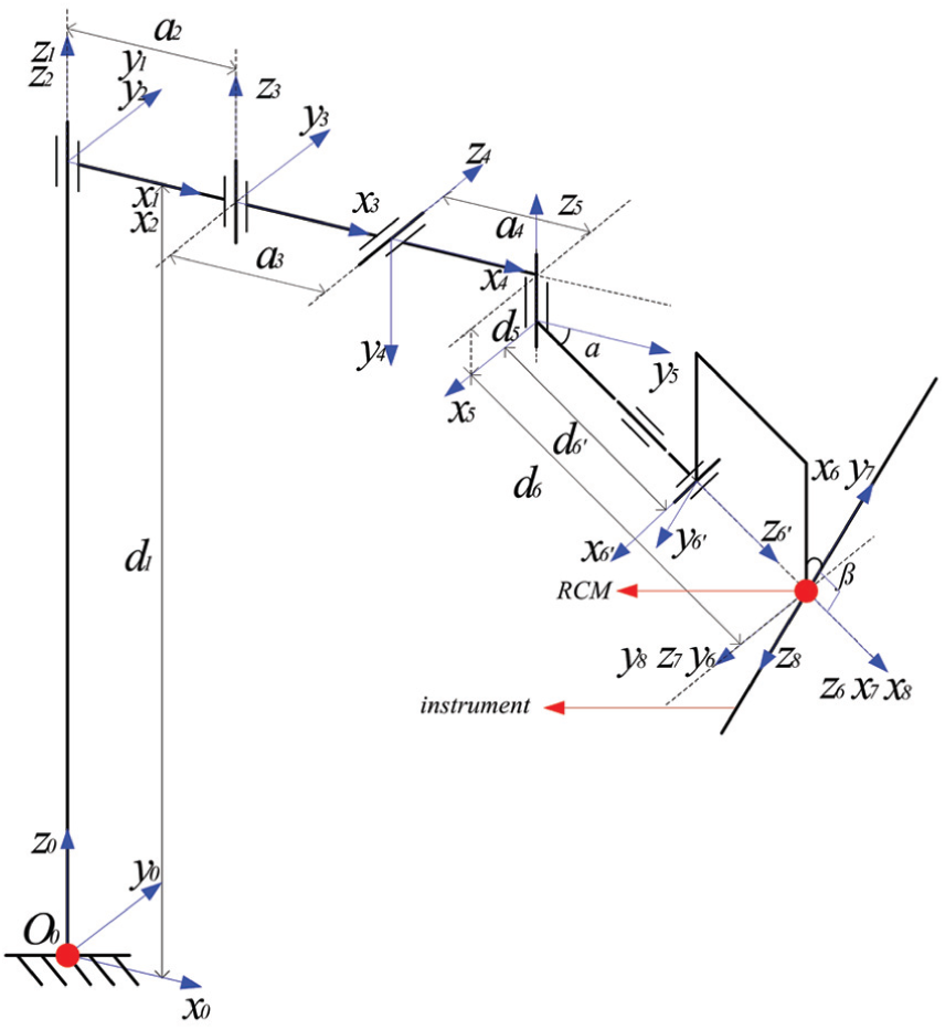
D-H coordinate system of the manipulator.
Based on Table 1, the transformation matrix of the mechanical arm in the joint space and the homogeneous transformation matrix in the base coordinate system can be obtained, respectively

where
D-H parameters of the manipulator.

Optimization of the minimally invasive surgery manipulator
The dexterity stands for the kinematics performance of the mechanical arm at a given pose position and orientation. Since the concept of dexterity was first introduced by Yoshikawa to the field of robotics in 1982, the dexterity index and many of its variations have been widely used in the evaluation and the optimization of mechanical arms.14–19 The manipulator designed in this article is composed of the preoperative positioning mechanism and the RCM mechanism. During the operation procedure, the joints of the preoperative positioning mechanism are locked, which will not be involved in the surgical operation. In addition, the dexterity of RCM mechanism is related only to the angle of the joints. Therefore, it is not significant to use the dexterity index of the mechanical arm as the global optimization goal.
As mentioned above, the integrated mechanical arms may result in collision. Therefore, for the dimensional optimization of the manipulator, the motion coordination among the mechanical arms should be considered as the main factor so that the system can reduce the possibility of collision and make the initial arm posture establishment become easy. The RCM kinematic mechanism and the preoperative positioning mechanism determine the position and orientation of the end-effector. The position of RCM point is completely determined by the preoperative positioning mechanism. Therefore, to satisfy the requirements of the minimally invasive surgery, the motion range of the RCM point should cover the operation area at least. How the RCM’s reachable range covers the target area can be used as the optimization index for the preoperative positioning mechanism.
Based on the previous analysis, this article will employ the following two factors as the major optimization objectives, that is, to maximize the coverage of RCM’s point in the target surgery area and to minimize the collision among the mechanical arms. The target operation area is simplified to a virtual surface with equal interval sampling points. The sampling point that satisfies the operation requirements will be selected as the potential RCM’s point. Based on that selection, the joint variables of the kinematics chain will be solved via the inverse kinematics model. If the value of the each joint variable is within the respective motion range, the selected RCM’s point is located in the target operation area. Then, the coverage range of the RCM’s point selected within the target area can be obtained. Moreover, by using the solved joint variable values, the spatial configuration of each mechanical arm can be determined based on the forward kinematics model. Finally, through the information above, the spatial geometric methodology can be utilized to estimate the interference among arms; based on that, an evaluation index will be proposed to assess the system mechanical design.
The target operation area model and the optimization index TAR
In this article, the target area of the abdominal minimally invasive surgery is modelled as a part of a cylinder, which covers a curved surface of 30 cm×40 cm×10 cm (the light green area as shown in Figure 4). That surface is hypothesized as the patient’s abdominal wall, which is meshed by a fixed-length distance. Each node on the meshed surface is a single RCM’s point, through which the laparoscope or the instrument will be inserted into the human body. The incision diameter is 10 or 12 mm, which depends on the laparoscope or the instrument used in the surgery. Smaller sampling interval will not improve the optimization results but makes the calculation process more complicated. In addition, the coverage of the operation target area of the laparoscope arm is different from the instrument arms’ due to the function differences. Figure 4 shows the sampling points of the instrument arm and the laparoscope arm, respectively.
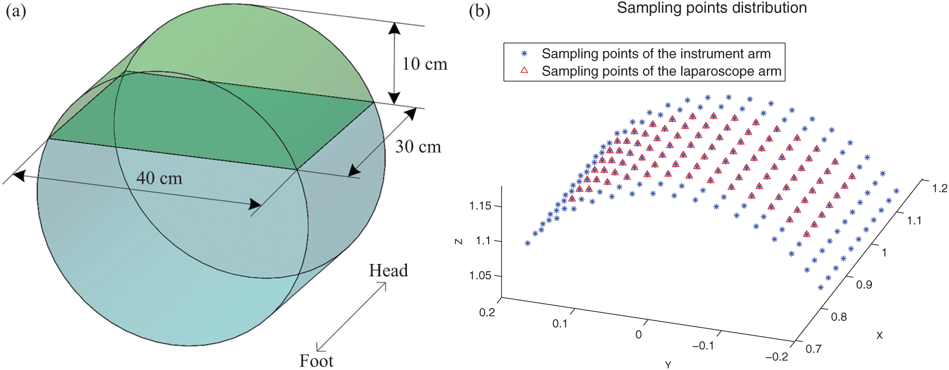
The surgical model and distribution of the sampling points.
To estimate whether the RCM’s point is located on the target operation area, one sampling point will be hypothesized as the potential RCM’s point first, and then the variable values of all joints in the preoperative positioning mechanism can be obtained via inverse kinematics model. If the solved variable values are in the range of motion (listed in Table 2), the RCM’s point can be located on the target area to check whether all of the sampling points will obtain the global information of the RCM’s points’ coverage on the operation target area.
Motion range of the kinematics joints.

Since the preoperative positioning mechanism includes 5 degrees of freedom, the inverse kinematics model features 2 redundant degrees of freedom for the position solving, which is a typical redundant inverse kinematics problem. In this article, a practical strategy is employed, that is, the redundant degrees of freedom are fixed so that the unique kinematics solutions can be solved when the RCM’s point is within the target operation area. Therefore, two joint variables can be set with specific values first, and then, the analytical solutions of other joint variables can be solved. Therefore, several groups of joints’ solution can be obtained when the motion range of the redundant joints is traversed with the equal interval step. Here, the variable values of the first and the second joints are assigned. The transformation matrix of the mechanical arm

Both sides of the equation are multiplied by the inverse matrices of the first three matrices, and equation (3) can be obtained

If the elements in the corresponding position between the both sides are compared, the following equations can be formulated

Assuming q2 and q3 are known, equation (4) can be solved

where
To evaluate a specific sampling point within the target operation area, the information of the solved joint variables will be used. If the variables’ value is within the joint motion range, the RCM’s point of the mechanical arm is one point of the target operation area. If the number of reachable sampling points and the number of total planned sampling points are n and N, respectively, the ratio of n and N is used as the optimization index of the mechanical arms. Therefore, the ratio of instrument arm and the laparoscope arm is defined as TARt and TARe, that is,
Selection of sampling point groups and the interference index NCS
As the typical preoperative implementation steps, three to five surgical incisions with diameter of 10–12 mm will be cut on the abdominal wall of the patients to establish the surgery channel for the instruments or the laparoscope. In Figure 5, it can be seen that the first incision is the access way for the laparoscope, the second and the third incisions are the surgical instruments’ channels and the fourth incision is the access way for the auxiliary surgical instrument. Minimally invasive incisions generally distribute in an isosceles triangle shape, and the instrument incisions are arranged on both sides of the laparoscope incision.

The distribution diagram of minimally invasive surgery (MIS) incisions.
Based on the requirements of minimally invasive surgery, different configuration groups of the incisions of the instruments and the laparoscope can be planned. Each configuration group includes two sampling points of instruments and one sampling point of laparoscope. If the sampling point of the laparoscope arm is assigned as the origin, a coordinate system can be established as shown in Figure 6. The incision configuration should meet the following constraints:
The incisions of instrument should be distributed on both sides of x-axis and the same side of y-axis.
The distance L3 between the two instrument incisions should be smaller than the maximum distance Ltt max and larger than the minimum distance Ltt min, that is,
The distances L1 and L2 between instrument incisions and laparoscope incision should be smaller than the maximum distance Letmax and larger than the minimum distance Letmin, that is,

The diagram of sampling points’ group.
All the incision configuration groups will be used in the mechanical arms’ interference analysis. For a certain configuration of the incision, a group of inverse kinematics solution for each mechanical arm (including the instrument arms and the laparoscope arm) will be obtained. The kinematics joints can be simplified into several points, whose position can be calculated by the transformation matrices.
For each sampling point group, according to the method previously mentioned, the solution set of inverse kinematics for each mechanical arm can be obtained. If the motion of the joint angles θ2 and θ3 in left and right instruments arms is limited within a specific range, the spatial position of each joint of the mechanical arms can be obtained. Therefore, the position relationship between the laparoscope arm and the instrument arms is shown in Figure 7.

The spatial position of the mechanical arms.
The prismatic joint d1 and the fourth rotary joint θ4 will not affect the position relationship between the links a2 and a4 and the other links in the x–y plane, so those joints are not shown in Figure 7. As shown in Figure 7, it can be seen that the interference mainly occurs under those two configurations, that is, the interference between the second rotary joint of the laparoscope arm and the links a2, a3 and a4 of the instrument arms, and the interference between the terminal link d6′ of the laparoscope arm and the terminal link d6′ of the instrument arms.
Interference between the second rotary joint of laparoscope arm and the links of instrument arm
In the x–y plane of the base coordinate system, the position of the second rotary joint of the laparoscope arm and the position of the second, third and fifth rotary joints of the instrument arms can be calculated based on the forward kinematics, that is, the coordinates of point P: e2(xp, xp), A: t2(xA, yA), B: t3(xB, yB) and C: t5(xC, yC). The distance between point P and line AB can be formulated as follows

As shown in Figure 7, if there is no collision between the second rotary joint of the laparoscope arm and the links a2, a3 and a4 of the instrument arms, point P should be placed at the left side of the directed lines AB and BC, and the minimum distance between point P and line segments AB and CD should be larger than the width of the link wr, that is, the following criteria should be satisfied

Interference between the terminal links of the laparoscope arm and the instrument arms
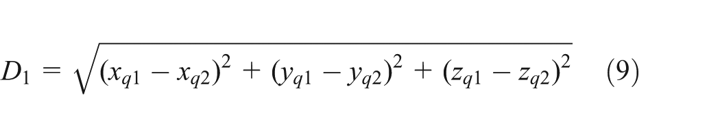
The distance between the RCM points of the instrument arm and the laparoscope arm is short, so the collision is prone to occur among the links d6′ of the three mechanical arms. To any specific incision configuration group, the spatial position relationship between the links d6′ of each arm can be evaluated via the shortest distance of the line segment. As shown in Figure 7, q1 and q2 are points on the line CD′ and EF′, respectively, so the equations of line CD′ and EF′ can be formulated as follows
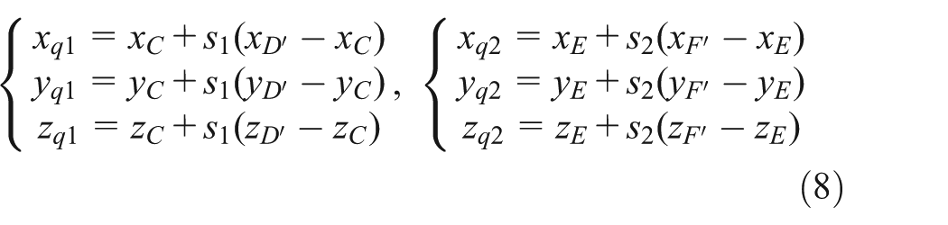
The distance between points q1 and q2 can be written as
The function can be obtained by substituting equation (8) into equation (9) as follows
Therefore, the calculation of the shortest distance between lines CD′ and EF′ can be converted into the question about the minimum value of function


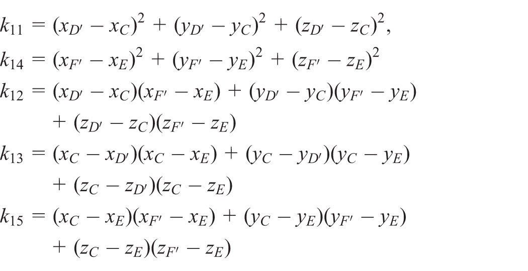
When

If s1 and s2 do not meet the requirements mentioned above simultaneously, points q1 and q2 are not on the line segments of links d6′. Here, the shortest distances between point C and line segment EF′, point D′ and line segment EF′, point E and line segment CD′, and point F′ and line segment CD′ can be solved, respectively. Among those four distances, the minimum value can be selected as the minimum distance between the two line segments, that is, the formulation below can be written as

Let the spatial coordinates of point E be
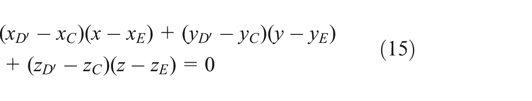
If the intersection point between that plane and the line CD′ is q3, the coordinate of point q3 can be written as follows based on the parameter equation of line CD′ and equation (15)

If

If

If

With the same method, the shortest distance Der between line segment EF′ and line segment GH′ can also be obtained. To avoid the collision between the link d6′ of the laparoscope arm and the link d6′ of the instrument arm, the following criteria should be satisfied

where wr is the minimum diameter of the link.
For each inverse solution in the incision configuration group, if criteria (7) and (20) are satisfied simultaneously, it means that there is no collision between mechanical arms for this configuration. Checking all the inverse solutions of each incision configuration group, the number of collision-free inverse solution

Case study based on NSGA-II method
In this article, the average number of collision-free inverse solution NCS and the reachable rate of mechanical arms within the target areas TAR are used as the main optimization objectives. Since the shorter links may increase the mechanical arm stiffness and make the structure more compact, the total length of the links and the spacing of the mechanical arms are employed as the second optimization objectives. Therefore, the optimization of minimally invasive surgical mechanical arms is a problem of multi-objective optimization. The various objectives of the multi-objective optimization question are usually coupled, so it is rather difficult to find an optimal solution to make all objectives optimal simultaneously. As a result, the solution of the multi-objective optimization problem is a set of non-inferior solutions, that is, the Pareto optimal solution set. For multi-objective optimization problem, in traditional methodology, the multi-objective functions are generally conversed into a single objective function optimization problem by weighting different objective functions. The effects of the various objective functions in the optimization can only be determined by the weighting factors. In addition, the selection of the weighting factors depends heavily on the practical experiences. In this article, the NSGA-II algorithm based on multi-objective optimization is adopted to optimize the links of the mechanical arm system.20–22 NSGA-II algorithm adopts the non-dominated sorting mechanism and introduces the calculation method with elitist strategy and crowding degree. It has been proved that the algorithm has high computational efficiency and stability. Now, the NSGA-II algorithm has been successfully applied in many engineering optimization designs and becomes one of the mainstream solutions to multi-objective questions. 23
The motion range and the target coverage of the laparoscope arm are different from those of the instrument arms. Therefore, in this article, the following parameters are taken as the optimization variables of the system, that is, the links and angle of the laparoscope arm ae2, ae3, ae4, de6 and αe, and the links and angle of instrument arm a2, a3, a4 d6, α as well as the spacing D0 between mechanical arms. Based on the analyses above, the overall optimization objective function of the manipulator can be formulated as follows

In the NSGA-II algorithm, either for the initialization-formed individuals or for the new generation of individuals, they can only select values within a given range of the variables which is determined by the limitations from the minimum permissible size of the mechanical arm and the operation space occupied by the overall system. The initial scope of each link is given in Table 3.
The initial range of optimization variables.

Results and analysis of the optimization
The target area is meshed by a constant-length distance of 3 cm. The minimum structural size of d6′ is 55 cm, the sampling interval of the second and third rotary joints is 5°, the total number of individuals in the population of genetic algorithm is 50 and the evolution algebra is 80. Then, the Pareto solution set obtained by NSGA-II is shown in Table 4. Finally, the optimal solution can be evaluated and selected via actual needs.
Results of optimization.
In order to meet the requirements of abdominal minimally invasive surgery, the workspace of the RCM point of the mechanical arms should cover the whole target operation area at least. Therefore, the TAR values of the mechanical arms should be considered as the primary index. The TAR value of instrument arms in the 5th group and the TAR value of laparoscope arm in the 6th group of Table 4 are lower than those of the other groups, and therefore the two groups of data should be excluded from the candidate list.
In addition, the Pareto solutions with a large NCS value should be chosen. If the NCS value is larger, the interference of the preoperative positioning mechanisms will less likely to occur and the establishment of initial position and orientation will be more flexible. The NCS values in the 2th, 4th and 8th group of Table 4 are much smaller than that of other groups, in other words, if we design the mechanical arms with the data of the 2th, 4th or 8th groups, the minimally invasive surgery robot in the preoperative placement is more prone to collide compared with other groups.
On the basis of the above analysis, in order to obtain high system stiffness, the total length of the links for each laparoscope or instrument arms should be as short as possible. For the purpose of making the robot system more compact, the spacing between mechanical arms should be as small as possible too. Hence, a compromising choice should be made between the total length Le, Lt and the spacing D0 according to your actual need. By analyzing the evaluation indexes above, in this paper, we prefer to choose the group of data with high value of NSC index. Finally, we take the data in the 7th group of Table 4 as the final optimal results of the minimally invasive surgical manipulator.
Conclusion
In this article, the mechanical design of an abdominal minimally invasive surgical manipulator is presented. From the perspective of the optimization, two evaluation indexes, that is, TAR and NCS, are proposed to maximize the motion range of the mechanical arms’ RCM point and minimize the interference possibility among the mechanical arms. In the optimization process, the NSGA-II algorithm is employed to calculate the length of the kinematics links of the manipulator. From the obtained Pareto solution set, the optimal dimension of the mechanical arms is selected based on the actual requirements. The optimization methodology outlined in this article can be used and extended in the design process of the similar minimally invasive surgical robot.
Footnotes
Declaration of conflicting interests
The authors declare that there is no conflict of interests regarding the publication of this article.
Funding
This research received no specific grant from any funding agency in the public, commercial or not-for-profit sectors.