
Abstract
The significant features of screw transmission are effort-saving and self-locking. Based on this, a screw-rod-type actuator is proposed, which is driven by a nut swung spirally together with piezoelectric transducers. The actuator consists of three parts: a nut fastened to a hollow cylinder, a precise screw rod, and two orthogonal piezoelectric vibrators worked on d 33 mode. The screw rod is forced to rotate and translate by traveling wave within the helical surface of nut, which is generated by two vibrators. First, the actuator’s running mechanism is preliminarily illustrated. Second, modal analysis and optimal design of the stator are performed through finite element method. Finally, the prototype actuator is manufactured and tested. The experimental results have proven that this driving manner is feasible, and the main characteristics are as follows: the stable working frequency is about at 9.5 kHz, and the maximum no-load speed and output force are approximately 61 r/min and 2.1 N, respectively, under 300 Vpp .
Introduction
In recent decades, many researchers have enduring interests in finding out the corresponding solutions to meet demands of precise positioning in micro and miniature devices. 1 One kind of them is utilizing piezoelectric-driven mechanisms, such as ultrasonic motors (USMs) and inchworm actuators. Their common features are as follows: compact structure, rapid response, high resolution, and so on, which are suitable for micro-electromechanical systems.2,3 So far, various piezoelectric actuators have been investigated. For example, Fernandez and Parriard 4 proposed a standing wave ultrasonic linear motor, improving the deformation amplitude and reducing the input parameter vibration ranges after the optimization stage. M.A. Erismis et al. 5 designed an inchworm actuator working in low voltage, which could provide large displacement and output force in in vivo biomedical applications. J.P. Li et al. 6 proposed a piezoelectric-driven rotary actuator by means of inchworm motion, and the designed actuator can realize large rotary ranges and speed with high accuracy. Besides the traditional actuators as given above, there is another kind of USM called as screw direct one. Professor Ueha first presented a linear USM directly driven by screw pair in 1989, while D.A. Henderson 7 made it practical by a screw-rod-type USM called SQUIGGLE motor in 2005, whose volume is only 1.55 mm × 1.55 mm × 6 mm and output force is 20 gf. At the same time, T.Y. Zhou et al. 8 proposed a nut-type USM and made it industrial, which could be integrated into the lens auto-focus system of camera. And then, J.T. Zhang et al. 9 first performed the theoretical analysis of screw-type actuator based on bending vibration in 2009 and proved that the screw rod was driven by both out-of-plane and in-plane traveling waves.
Among these piezoelectric actuators, the screw-type USMs are the simplest and most compact, so they are helpful to meet the needs of miniaturizing application, such as implantable drug pumps, mobile phone cameras, and automobile door lock system. Currently, most of these kinds of motors are driven by d 31 mode piezoelectric ceramic transducers, which are usually used as surface-mounted devices. Because their volumes are generally small, the transducer’s capacity of electromechanical conversion is inadequate. Therefore, the output torque as well as the power of the actuator is limited. In addition, the patched piezoelectric ceramic is weak in tensile capacity, easily broken under high-frequency vibration. In response to these weaknesses of d 31 mode piezoelectric transducers, a linear actuator of screw type with double piezoelectric vibrators based on d 33 mode is proposed.
Structural design and working principle
Configuration of stator
The photo of a prototype actuator is shown in Figure 1(a). Its stator mainly consists of two elastic vibrators and a precise nut fastened to a hollow cylinder, while the rotor is only a screw rod with high precision. The nut is set on one of the end faces of the hollow cylinder and matched with the rotor. In addition, a thin guiding cover is patched on the other end face of the cylinder, providing guidance for the screw rod. Two elastic vibrators are set perpendicular to each other in space and assembled with the hollow cylinder by interference fit through solid horn. The cross section of the solid horn is relatively less than that of the upper block in order to amplify the vibration displacement or velocity amplitude. 10 Both of the two vibrators are adopted Langevin configuration, that is, the fixed seat, upper and lower blocks, and piezoelectric transducers are all fastened together by a bolt, through which the preload to piezoelectric transducers can also be adjusted.

Prototype actuator and configuration of piezoelectric transducers: (a) photo of a prototype actuator and (b) configuration of piezoelectric transducers.
Figure 1(b) illustrates the alignment of piezoelectric transducers and their connection manner in detail. Each vibrator consists of four pieces of piezoelectric ceramics, and every piece is cut into two halves and aligned in opposite polarized direction. Every two pieces of ceramics in sequence are assigned to phase A or B and excited by high-frequency signal of sinusoidal voltage sin ωt or cos ωt. A single vibrator is designed to be symmetrical in order to reduce the dielectric loss, because the input impedance is low in this case.11,12 Here, the so-called symmetrical design means that the geometric parameters of the upper and lower blocks are the same. In addition, the two elastic vibrators have consistent modal frequency in theory because they are structurally identical to each other.
Working principle
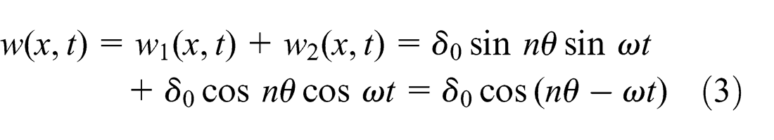
Whether for phase A or B in each vibrator, a standing wave within the thin wall of cylinder can be generated independently under voltage excitation. Therefore, two standing waves are also obtained simultaneously through both phases A and B.13,14 And a circumferential bending traveling wave can be achieved by the synthesis of the two standing waves, when the following conditions are met: (1) driving voltage is consistent in amplitude and frequency, (2) phase difference in time is just ±π/2, (3) phase difference in space is π/2, and (4) bending vibration mode is appropriate. Assume that the displacement equation of the bending standing wave generated by phase A can be expressed as follows

where δ 0 is the amplitude of the point on the neutral surface, n is the number of pitch diameter, θ is the angle in space, and ω is the angle frequency of driving voltage.
Similarly, the displacement equation generated by phase B can be expressed as

Then, the bending traveling wave within the thin wall of the hollow cylinder is synthesized and expressed as the following equation
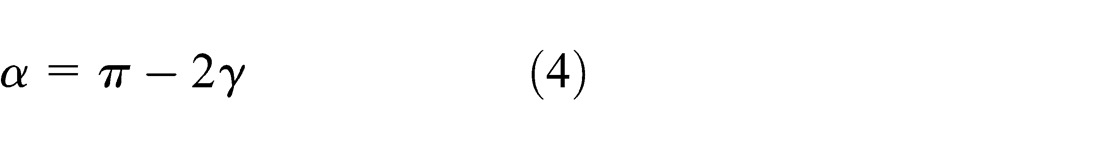
Based on the above analysis, the motion equation of any point P on the helical surface of nut can be derived.15–17 The interactive relation of the nut and the screw rod is preliminarily illustrated in Figure 2(a). In this diagram, the angle α is the thread angle of the screw pair and angle γ or γ′ is the angle between the trajectory plane and the XY plane, where γ′ is the real angle and γ the ideal one. The so-called trajectory plane is defined here as that in which driving points are located. For the actuator based on bending vibration, in this article, the end face of the hollow cylinder is the real driving surface, which means most of the driving points are concentrated within the XY plane. Ideally, if the ellipse trajectory plane is always kept perpendicular to the helical surface of nut during runtime, the electromechanical conversion efficiency will be satisfied. Therefore, the performances of the actuator can be improved to the greatest extent possible. At the moment, the angle γ′ is equal to γ. And the relationship between angle α and γ ought to meet the criteria as follows

Analysis diagram for the working principle of screw-type actuator: (a) interactive relation of the nut and screw rod and (b) forming of the ellipse trajectory.
For the screw-type actuator, the bending vibrations have to be passed to the helical surface of nut in order to drive the screw rod. That means only when the trajectory of the point within the helical surface is elliptical do the actuation be accomplished. Figure 2(b) illustrates the forming of ellipse trajectory.
Assume that P(δ,τ) is an arbitrary point on the helical surface, and its original position before deformation is P 0. In the ideal situation, that is, γ′ = γ, the displacement equation can be expressed as follows

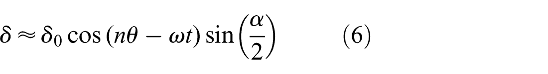
where h 0 is the distance measured between the driving surface and the neutral layer, and ϕ is the deviation angle of the radial section before and after bending deformation. It is obviously very small. Therefore, equation (5) can be approximately expressed as δ = w(x,t)sin(α/2). Substituting equation (3) into equation (5), the normal displacement of point P can be expressed as follows
And similarly, the tangential displacement equation of point P can be obtained as follows

Obviously, based on equations (6) and (7), we can draw conclusion that the normal and tangential displacements of the arbitrary point P meet the criteria of elliptic equation
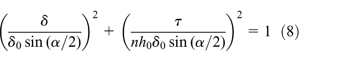
So far, in the helical contact region of the nut and screw rod, the elliptical motion of points can provide tangential driving force for the rotor through friction, and then the screw rod is forced to rotate and move along the axial direction.
And then, by taking first derivative to equation (7), the tangential speed of point P on the helical surface can be obtained as follows

where the minus in equation (9) indicates that the vibrating direction of point P is contrary to the propagation direction of the traveling wave.
Next, the coupling formulations of piezoelectric transducers and structures ought to be analyzed.
Electromechanical coupling model of the actuator
Based on Hamilton’s Principle, the dynamic system of piezoelectric actuator can be expressed as follows
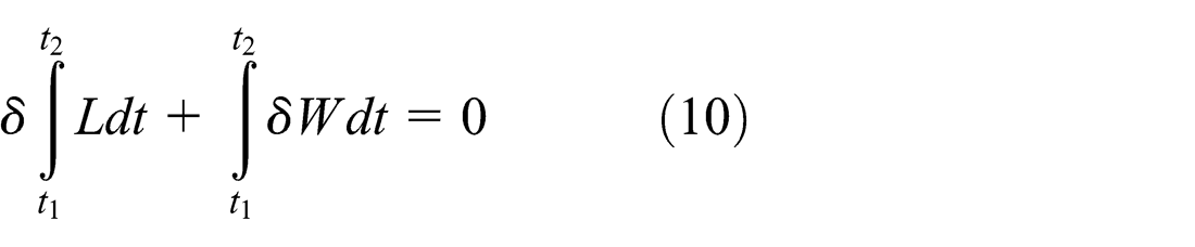
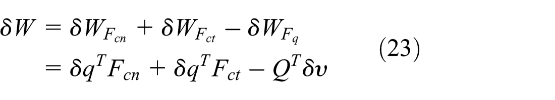
where L is the function of Lagrange and δW is the sum of virtual work done by the non-potential force. Their detailed explanations are as follows

In the above equation, Ek, Ep , and Ee are, respectively, the kinetic energy of the transducer system, the potential energy of the system, and the power stored in piezoelectric ceramics

That is, δW includes virtual work done by not only the normal force Fcn and tangential force Fct on the contact surface but also the equivalent exciting force of piezoelectric ceramics in the general coordinate system.
For the screw-type actuator, the bending mode of the piezoelectric vibrator is adopted. According to vibration theory, the bending deflection of beam can be expressed as
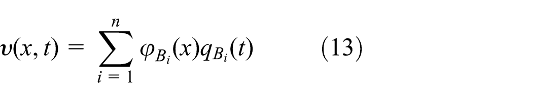
where
Under this mode assumption, the dynamic model considering electromechanical coupling relation could be discussed. In the study by Zhao et al., 18 a utility method for parameter analysis and optimization is presented. Here, we adopt this method. According to equation (10), we analyze the Lagrange function L and virtual work δW separately.
First, the modal parameters used in the Lagrange function should be declared, so the variation in Lagrange function can be expressed by them. Based on equation (11), L includes three parts, that is, Ek, Ep , and Ee . For the vibrator system, the kinetic energy is composed of two parts, which exists in elastic parts and piezoelectric ceramics. It can be expressed as follows

where Mp is the modal mass of transducers corresponding to the modal coordinate.
The potential energy of the system is also the sum of two parts, that is, pure mechanical potential energy Vpp exists in piezoelectric ceramics and that of Vpcp generated by electromechanical coupling effect. It can be expressed by the equation below
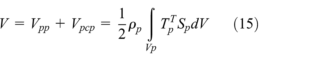
where Tp and Sp are the stress matrix and the strain matrix, respectively.
The electric energy of the system is composed of two parts, too. They are electric energy that exists in piezoelectric ceramics and that generated by electromechanical coupling effect. The energy could be expressed as follows

where Cp
is the modal capacitor and
Now, the variation in the Lagrange function can be obtained as follows

Then, we discuss the virtual work δW on the piezoelectric vibrator by the modal force. Based on equation (12), δW also includes three parts, that is,
The virtual work done by the modal force in the contact interface is
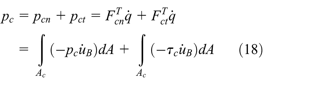
where pc
is the normal force in the interface,
As

The virtual work done by the exciting force of piezoelectric ceramics can be expressed as

where Tp and Sp are the stress vector and strain vector of piezoelectric ceramics, respectively.
Then, the exciting force of piezoelectric ceramics can be expressed as follows

where
The accumulated charge in piezoelectric ceramics is

Therefore, the virtual work done by the non-potential force can be expressed as follows
Now substituting equations (17) and (23) into equation (10), the dynamic equation considering electromechanical coupling relation can be obtained as follows

Based on the variation property, equation (24) can be solved if the equation below is met

where Dp is the coefficient of modal damping.
For the screw-type actuator working on bending mode, the dynamic equation can also be expressed briefly by modal parameters as follows

The above equations (24)–(26) provide theoretical reference for rod-type piezoelectric actuators to carry out simulation analysis and structural optimization, which work on bending mode.
Simulation analysis of stator
As is well known, both the material and structure parameters are crucial for stator as they will directly affect the output performance of the actuator. In order to reduce the mass and increase the torque density, duralumin is chosen as the material of hollow cylinder. In addition, adopting low-density metal is also good for the solid horn to ensure that most of vibration energy radiate efficiently from the front end face. The solid horn and upper block are designed as a whole and their diameter ratio is about 1:3, which can increase the magnifying coefficient of amplitude. 19 The material of the lower block ought to be a high-density metal, which is No. 45 steel in this article, which will improve the forward radiation power of vibrators. According to the stator structure design in Figure 1, the modal analysis was performed by means of finite element method (FEM). 20 Figure 3 is the finite element model of stator established by ANSYS 12.0.

Finite element model of stator: (a) front view and (b) back view.
The model is based on the following assumptions or conditions: (1) thickness of the electrode sheet is ignored as it is only 0.05 mm, (2) mechanical boundary condition is a fixed constraint put on the end face of two vibrators, and (3) coupling voltage is set as zero at nodes in the electrode region.
Next, the effects of structure parameters on vibration will be discussed in detail by FEM. Figure 4 provides the influence of vibrator length on the maximum amplitude and modal frequency in first-order bending vibration. As the thickness of lead zirconate titantate (PZT) is 6 mm, the vibrator length is set as 26 and 36 mm as well as 46 mm, respectively. The results indicate that the modal frequency and amplitude both decrease with the increase in length.
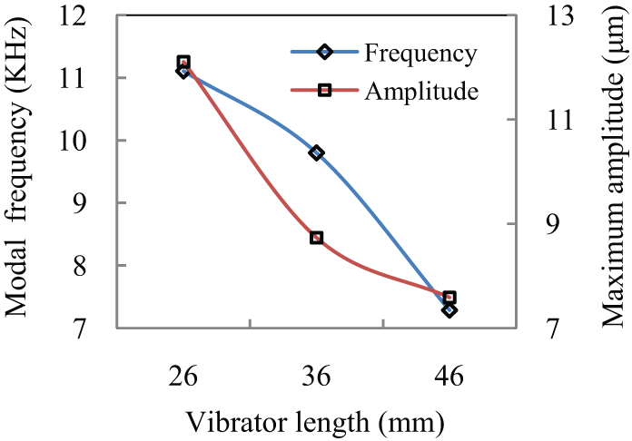
Impact of vibrator length on maximum amplitude and modal frequency.
From Figure 4, when the vibrator length is 26 mm, the amplitude of the point within the end surface of the hollow cylinder is the largest. The maximum amplitude appears near the external circular surface (just like the red region shown in Figure 7(a)), which is in the middle of two joints connecting the cylinder and vibrator. For the screw-type actuator, the real positions of driving points concentrate on the inner spiral surface of the nut, which is closer to the central line of the cylinder than the external circular surface. The analysis results indicate that the amplitude of the point within nut’s internal surface is too small (approximately zero) to drive the screw rod efficiently, when the vibrator length is 26 mm. But if the length is changed to 36 mm, the amplitude of nut’s point is large enough (more than 5.823 µm), although the maximum amplitude is not the largest. Therefore, the vibrator length finally is determined as 36 mm.
The other parameter to be discussed is the diameter ratio of the hollow cylinder. Figure 5 illustrates the simulation results, which are obtained under vibrator length of 36 mm and outer diameter of hollow cylinder of 30 mm. The diameter ratio varies and is set as 3:2, 15:8, and 5:2, respectively. The results show that the comparatively better performances of the stator occur under the condition that the diameter ratio is 3:2. In addition, during the analysis, an interesting phenomenon was found that the modal frequency is irrelevant to diameter ratio.

Impact of the diameter ratio on the maximum amplitude and modal frequency.
Finally, we discuss the impact of cylinder length. The preconditions for simulation are as follows: vibrator length of 36 mm, outside diameter of cylinder of 30 mm, and diameter ratio of 3:2. The cylinder length is set as three sizes: 12, 16, and 20 mm. Figure 6 provides the simulation results. It shows that the modal frequency decreases with increasing cylinder length, but the maximum amplitude occurs at the condition the cylinder length is 16 mm. So, the optimal length for the hollow cylinder can be determined as 16 mm.

Impact of cylinder length on maximum amplitude and modal frequency.
Based on the above simulation results, the stator’s structural parameters are decided and illustrated in Table 1 in detail.
Structure parameter of the stator.

PZT: lead zirconate titantate.
In the frequency range of 0–37 kHz, the modal analysis of the stator is performed by means of the block Lanczos method, and the first 16 orders of mode shapes and their frequencies are calculated. The frequency results are shown in Table 2 in detail.
The results of modal analysis of the stator.
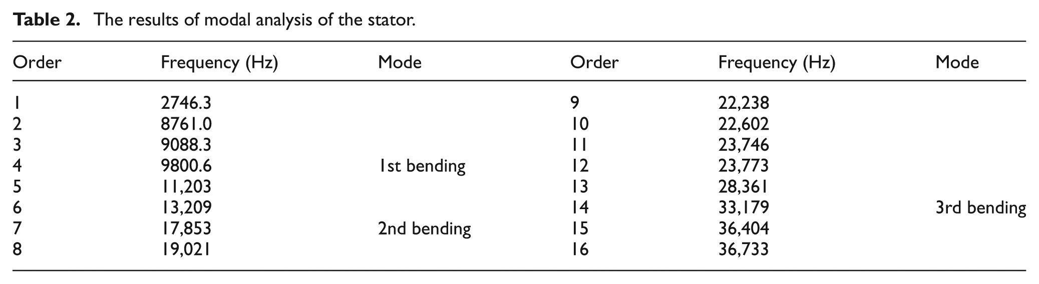
On the basis of the above simulation, there are a total of three orders of bending vibration mode existing in the frequency range of 0–37 kHz, and their modal shapes are shown in Figure 7(a)–(c), respectively.

The first three orders of bending vibration mode of the stator: (a) first-order bending, (b) second-order bending, and (c) third-order bending.
Generally, the modal shape with no pitch-circle ought to be selected as the working mode of the actuator. Besides, the vibration frequency should not be too high, due to the higher resonant frequency, the bigger vibration attenuation, and the larger energy loss of piezoelectric transducers. 21 Therefore, the first-order mode of bending vibration is determined as the working mode of the stator, and the modal frequency is 9.801 kHz. And the whole modal shape of bending vibration is shown in Figure 8.

Working modal shape of the stator: (a) right view, (b) front view, and (c) left view.
Experiment and discussion
Experimental analysis
The prototype actuator has been manufactured as shown in Figure 1, where the precise nut and screw rod are NTFL10 × 40 and FAB10 × 100 made in MISUMI Corporation, and the material is SUS304. The piezoelectric transducers belong to PZT-4 series. Figure 9 shows the testing system for the screw-type actuator.

Testing system for the screw-type actuator.
It mainly includes a double-channel arbitrary waveform generator (RIGOL DG4102), power amplifier (Tabor 9200 A), laser micrometer, push–pull dynamometer, air-bearing table, prototype actuator, and so on. The main performance of the actuator, such as output speed and force, can be measured by this testing system.
Figure 10 is a curve describing the output speed versus driving frequency of the actuator. The driving frequency is regulated in the range from 9.0 to 10.0 kHz. The results indicate that the maximum speed of the actuator is 61 r/min and the real optimal working frequency is 9.5 kHz.
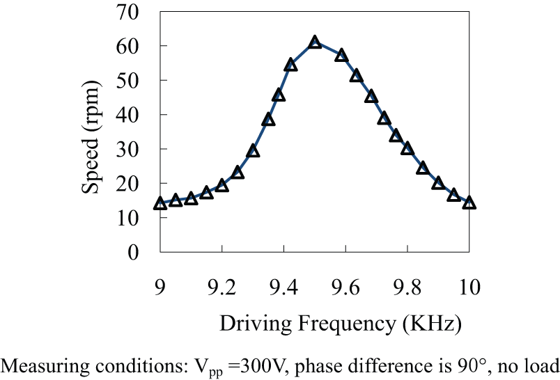
Relationship between output speed and driving frequency.
The theoretical maximum rotary speed of the actuator should be limited by the driving point’s velocity in circumferential direction within nut’s inner spiral surface. If there is no relative slip occurring in the driving point, the rotor can get the maximum linear velocity. This is determined by equation (9), and the maximum tangential speed can be expressed as follows
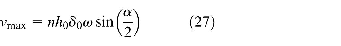
Converting linear velocity into rotary speed, the maximum rotary speed of the actuator in theory can be obtained

Compared with the tested result, the mechanical conversion efficiency of this actuator can be simply valuated by equation (26). It is not satisfied and to be improved later

Figure 11 illustrates the relationship between the driving voltage and the axial output force as well as the rotary speed. The measuring conditions are also shown in this figure.
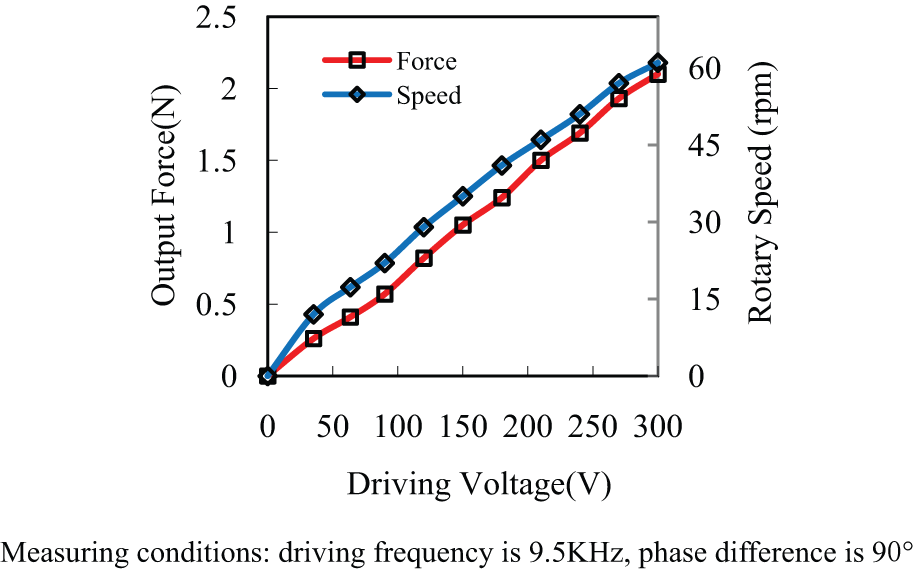
Testing result of output force and speed versus driving voltage.
It can be seen that when the voltage varies from 0 to 300 V, both the axial force and rotary speed of the screw rod grow linearly. The maximum output force of the actuator is approximately 2.1 N under 300 Vpp . In addition, the tests are made through push–pull dynamometer; experimental results indicate that the pull force is in good agreement with that of push. And the maximum speed is 61 r/min under 300 Vpp .
For any actuator, the most important performance index is the mechanical characteristic. That means the relationship of the output force versus the rotary speed ought to be identified by measurements. The testing conditions are as follows: Vpp is 300 V, the driving frequency is locked at 9.5 kHz, and the phase difference is 90°. The approximate testing results are shown in Figure 12. The axial output force is inversely proportional to the rotary speed. The curve appears in near-linear trend.

Mechanical characteristic of the screw-type actuator.
Results and discussion
The real working frequency of the actuator is measured at 9.5 kHz, corresponding approximately to 9.801 kHz calculated by finite element analysis and slightly lower than the simulation result. The difference is mainly caused by uneven clearance that existed in conjunction with the solid horn and the hollow cylinder.
The maximum axial force is only 2.1 N under the highest driving voltage. It is too weak for an actuator to be satisfied. The major reason is that the driving points are extremely close to the axis of the screw rod because the structure design like prototype is inevitably limiting all driving points within the helical surface of a small nut. During the experimental process, it is found that the driving capacity in the peripheral area (including end face and outer circle) of the cylinder is much larger than that of the central area. Next, in order to make full use of driving capacity in outer edge and end face, the structural design will be improved. For instance, an extra rotor could be set between the screw rod and the cylinder. The rotor is a flat barrel with a taper hole, which contacts a cone cylinder under certain preload. Under this condition, the rotor can be driven by traveling wave whether in-plane or out-of-plane.
In addition, there is comparatively loud noise during the testing process. It is perhaps brought about by the following reasons: (1) the driving frequency is only 9.5 kHz and beyond ultrasonic frequency range, (2) the traveling wave is impure because of the poor consistency on the modal frequency of two vibrators, (3) lack of guidance caused by short cylinder, and (4) lateral vibration of screw rod might exist.
Conclusion
A linear piezoelectric actuator of screw type with double vibrators based on d33 mode is proposed, and the driving mechanism is preliminarily analyzed. The elliptic equation of the driving point’s trajectory within the driving surface is simply derived, and the modal analysis of the stator is performed by FEM. The first-order mode of bending vibration is finally determined as the working mode of the actuator. The theoretical modal frequency is 9.801 kHz and that of the real is 9.5 kHz.
The prototype actuator is manufactured, and the main output performances are measured on the corresponding experimental system. The tested results show that this screw-type actuator is capable of continuous operation. The rotating direction can be achieved by regulating phase difference at ±90°, and the output force as well as the rotary speed can be adjusted through driving voltage. The stable working frequency is about 9.5 kHz and the maximum axial force output from the screw rod is 2.1 N. In the condition of no-load, the maximum rotary speed and output force are 61 r/min under 300 Vpp and 9.5 kHz, respectively.
The experimental results show that double vibrators of d 33 mode can effectively generate circumferential traveling wave within a hollow cylinder and then drive a screw rod directly through the helical surface of a nut. It is proved that this driving manner is feasible, and the research works have a certain reference value for utilizing precise screw pair in miniature devices.
Footnotes
Acknowledgements
The authors thank Professors Yiqiang Wang and Xuechang Zhang of Ningbo Institute of Technology, Zhejiang University, for their valuable suggestions to this work.
Academic Editor: Hung Nguyen-Xuan
Declaration of conflicting interests
The authors acknowledge that there is no conflict of interest with respect to results/findings with any other agencies or individuals.
Funding
The authors would like to thank the National Natural Science Foundation of China for supporting this work through NSFC-51275467.