
Abstract
The helicopter tail drive shaft is vulnerable to penetration damage from ground anti-aircraft fire in low-altitude combat. The crack around the bullet hole will be propagated under torsional fatigue loading, which can result in shaft fracture and significantly jeopardize flight safety. Considering the effect of the projectile incidence angles and radial offsets on its damage morphology, finite element analysis and two-stage light gas gun experiment are performed to investigate the detailed damage characteristics, and the effects of two typical impact parameters on the crack propagation life of the tail drive shaft have been further analyzed. A simplified bullet hole morphology is established based on geometric similarity. The crack propagation life of the damaged tail drive shaft is investigated through a combined approach of finite element analysis and fracture mechanics theory. The results show that an increase in the incidence angle and radial offset causes the axial and radial damage dimensions of the bullet hole to gradually expand, and the degree of damage of the tail drive shaft gradually increases. The crack propagation life of the damaged tail drive shaft shows a declining trend, and radial offset impacts have a greater effect on crack propagation life than incidence angle impacts.
Keywords
Introduction
Helicopters are often required to fly at low altitudes during military strike mission execution to engage targets, thus the tail drive shaft is vulnerable to targeted attacks from ground-based anti-aircraft guns, which will result in projectile impact damage.1–6 The helicopter tail drive shaft is a thin-walled structure, which is the core component to transfer power from the helicopter engine to the tail rotor. Once the tail drive shaft is damaged by the projectile, crack nucleation occurs around the bullet hole under torsional loading, the crack around the bullet hole will then propagate under operation, ultimately leading to fracture failure. This will result in the loss of power transmission capacity of the tail drive system, and the tail rotor will be unable to generate adequate anti-torque, causing the helicopter to crash and resulting in personnel casualties.7,8 To ensure the safety and reliability of the tail drive shaft, research on its impact monitoring and damage assessment is required,9–13 the analysis of the damage morphology characteristics and fatigue crack propagation life of the impacted tail drive shaft provides a research basis for the subsequent damage assessment.
So far, some studies have been carried out on projectile impact damage to the helicopter tail drive shaft. Gilioli et al. 14 established a numerical model for the projectile impact on the tail drive shaft, and found that the rotational speed of the tail drive shaft had almost no effect on the projectile trajectory and the projectile and shaft damage morphology. Manes et al. 15 investigated the damage pattern and degree of damage caused by different bullet types impacting the tail drive shaft, and concluded that soft-core bullets cause more severe damage to the tail drive shaft than rigid bullets. Lumassi et al. 16 considered the deformability of the projectile and used a deformable projectile to simulate the impact on tail drive shafts with and without protective frame panels, and obtained the damage and failure morphology of the tail drive shaft subjected to projectile impact. Zhang et al.17,18 established a dynamic model of the tail drive shaft system with ballistic damage and analyzed the effects of ballistic impact parameters on its dynamic characteristics. However, ideal geometric damage was used to simplify the ballistic penetration damage morphology. The resulting morphology had a certain error compared to the actual morphology.
Conducting a study on the crack propagation fatigue life of helicopter tail drive shafts is essential to ensure that helicopters have sufficient time to land safely even after being impacted by a projectile. Colombo and Giglio19,20 conducted numerical simulations of projectile impact on the tail drive shaft. The results identified the impact conditions that caused the most severe damage, and the crack propagation fatigue life was also determined for this condition. Fossati et al. 21 performed numerical simulations and experiments on projectile impact and fatigue crack growth in tail drive shafts, successfully simulating and predicting the fatigue crack propagation process. Mi et al. 22 established a crack propagation model for the damaged tail drive shaft after projectile impact to predict the fatigue remaining life. However, the modelling of the bullet hole in the tail drive shaft is not described. Zhou et al. 23 proposed a reduced-order simulation method for the probabilistic assessment of helicopter structural component remaining life, which achieves real-time prediction of crack propagation in complex structures with minimal computational effort. Wan et al. 24 established a full-size helicopter tail structure finite element model, and employed cumulative damage analysis to predict its fatigue life. Shahani and Mohammadi25,26 employed the damage tolerance method to estimate the fatigue life of helicopter main rotor blades under random loading, determine the minimum extended crack length, and comprehensively examine the influence of initial crack length on crack growth. However, the studies on damage morphology characteristics of the helicopter tail drive shaft under different impact conditions and the effect of projectile impact damage on its crack propagation life are relatively scarce. Most scholars focus on the failure modes of targets, with insufficient exploration of the damage mechanism. Moreover, the mechanism by which impact damage affects crack propagation life remains unclear. Considering the complexity of the fracture mechanics modelling method, a simplified model was derived from the dynamics analysis of the projectile impact, and the crack propagation life of the tail drive shaft after projectile impact was investigated by combining fracture mechanics theory with the finite element method, revealing the effect of impact damage on crack propagation life.
In this paper, the finite element dynamics model of a helicopter tail drive shaft impacted by a projectile is established, and the model is verified through the projectile impact experimental test conducted on the high-speed impact damage simulation test platform. The effects of incidence angle and radial offset on the impact damage morphology characteristics and crack propagation life of the tail drive shaft are analyzed. A method to simplify the morphology of damage holes is proposed. Simplified modeling of the damaged tail drive shaft is performed using the morphological simplification method. The stress distribution around bullet holes caused by incidence angle and radial offset impacts is analyzed, and a study on the fatigue crack propagation life of the tail drive shaft under two impact conditions is carried out by co-simulation finite element analysis. Based on the above research, the damage characteristic and the fatigue crack propagation life of the tail drive shaft subjected to the impact of the projectile under two types of impact parameters are summarized. These studies provide a reference basis for subsequent condition monitoring and damage assessment of the helicopter tail drive shaft after impact by a projectile, which is strategically significant for ensuring the safe flight and mission execution of helicopters.
The damage morphology characteristics of the tail drive shaft and its simplified bullet holes morphology
The numerical simulation model of impact dynamic analysis
Considering that the projectile impact on the tail drive shaft only caused local damage, a section of the horizontal tail drive shaft from a specific helicopter type is selected as the impacted object in this paper. The explicit dynamics analysis module in the ABAQUS finite element analysis software is used to perform the projectile impact dynamic analysis of the tail drive shaft. 27 The outer diameter of the tail drive shaft is 100 mm, with a wall thickness of 2 mm and a length of 800 mm. Since failure and destruction after projectile impact primarily occur near the impact point, a refined and structured mesh is used around the impact zone to better represent the projectile impact damage morphology. 20 The mesh size in the dense area is 0.4 mm × 0.4 mm × 0.4 mm, five elements are meshed in the thickness of the shaft. A coarser structured mesh is used in other areas. The element type is the reduced-integration three-dimensional eight-node hexahedral element (C3D8R), with default hourglass control. The tail drive shaft is composed of a total of 3,081,120 solid elements, and element deletion is activated. The impactor is a 14.5 mm caliber truncated-ogive projectile. 5 The projectile deformation is ignored, and it is defined as a rigid body.16,19 The finite element model for the projectile is constructed from 11,242 C3D8R elements. The numerical simulation model of projectile impact on the tail drive shaft is shown in Figure 1.

Simulation model of projectile impact on the tail drive shaft.
The projectile incidence angle is defined as the angle between its central axis (velocity direction) and the normal line to the central axis of the tail drive shaft, denoted as
The material of the helicopter tail drive shaft is 6061 aluminum alloy, and the material of the projectile is 45 steel. Projectile penetration problems typically involve the dynamic characteristics of materials. The widely used and effective Johnson–Cook (J-C) material model was proposed to simultaneously describe such effects as strain rate hardening and thermal softening.1,28 The J-C constitutive model and failure model are adopted in this paper to capture the dynamic behavior of the tail drive shaft subjected to projectile impact. 15 The J-C constitutive model can be defined by:
Where
The J-C failure model is defined as:

Where
The constitutive model parameters for the tail drive shaft selected in this paper are shown in Table 1. 29 The projectile material is characterized by a density of 7810 kg/m3, an elastic modulus of 200 GPa, and a Poisson’s ratio of 0.26. 30
Constitutive model parameters of 6061 aluminum alloy.

Projectile impact simulation experiment
To validate the accuracy of the established numerical simulation model for the projectile impact dynamic analysis, a projectile impact experiment is conducted. The projectile impact experiment is carried out on a high-speed impact damage simulation test platform, as shown in Figure 2. The main structure of the high-speed impact damage simulation test platform is a two-stage light gas gun, which consists of a first-stage barrel and a second-stage barrel. The test platform also includes a launch control console, a gas distribution system, a target chamber, a magnetic induction velocimeter, etc. The high-pressure gas distribution system delivers high-pressure gas to the high-pressure gas storage tank for charging and pressurization to enable the launch of the projectile at different speeds. Once the predetermined chamber pressure is reached, the projectile is launched via the launch control console. The projectile speed is captured via the dual induction coils in the magnetic induction velocimeter. The target chamber houses a clamping device, which is used to clamp the tail drive shaft. The clamping device can be adjusted in terms of angle by adjusting the positioning hole, and can be moved freely to meet the impact of the projectile under different impact conditions. The impact process is as follows: the high-pressure gas is used to drive a piston to compress the gas in the first-stage gun barrel, and when the gas pressure is high enough, the gas breaks through the diaphragm at the connection and gives the projectile and sabot an initial acceleration for further acceleration in the second-stage gun barrel. Subsequently, after separation facilitated by the sabot separation device, the projectile impacts the aluminum shaft fixed by the clamping device in the target chamber.

High-speed impact damage simulation test platform.
Using this experimental setup, impact experiments are conducted with a 0° incidence angle, a 30° incidence angle, and with a radial offset of 25 mm. The bullet hole damage morphology on the tail drive shaft is obtained. In this experiment, the projectile and the impacted tail drive shaft are adopted with the same structural dimensions and material properties as in the simulation model, and the impact velocity of the projectile is approximately 430 m/s. In order to reduce the error between the impact conditions in the projectile impact experiment and those in the projectile impact simulation model, the clamping device should be adjusted to position the light gas gun muzzle as closely as possible to the impact point. The morphological comparison between the simulation and the experimental results under the same impact conditions is shown in Figure 3 below. The morphology comparative analysis of the bullet holes indicates good agreement between the simulation and experimental results, thus validating the accuracy of the model for projectile impact dynamic analysis established in this paper.
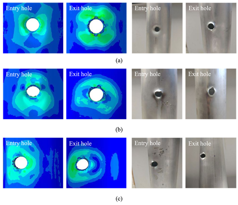
Morphology comparison between impact simulation and experiment under different impact conditions: (a) 0° incidence, (b) 30° incidence, and (c) 25 mm radial offset incidence.
Influence of incidence angle and radial offset on tail drive shaft damage morphology
The damage morphology of the tail drive shaft following projectile penetration is the main topic of discussion in this section. Numerical simulations of projectile impact on the shaft are conducted with incidence angles of 0°, 15°, 30°, 45°, and 60°, and the impact point of the projectile is located at the center of the tail drive shaft. To ensure that the projectile impact on the tail drive shaft can form double bullet hole penetration damage morphology, according to the geometric relationship, the maximum radial offset of the double bullet hole damage can be calculated as the tail drive shaft’s radius minus the projectile’s radius. The offset within the maximum radial offset is selected as the impact condition for subsequent simulation. Projectile impact simulations are conducted with radial offsets of 0, 15, 20, 25, and 30 mm from the center of the tail drive shaft. The damage morphology of the entry and exit holes under different incidence angles and radial offsets is shown in Figures 4 and 5.

Tail drive shaft projectile impact morphology under different incidence angles.

Tail drive shaft projectile impact morphology under different radial offsets.
According to Figures 4 and 5, during the projectile impact penetration process, the projectile impact causes the elements to fail, due to the existence of axial force and circumferential stress at the time of the element failure, 21 the tail drive shaft experiences tearing damage in the axial and circumferential directions as the projectile contacts the shaft. Furthermore, debris spallation occurs during the penetration process, leading to the entry and exit holes exhibiting the tearing damage and burrs shown in the figures. The continuous penetration of the projectile causes the tensile stress in the internal elements of the tail drive shaft to reach the tensile strength limit, resulting in element failure and crack formation around the bullet hole.
From Figure 4, as the incidence angle increases, the contact area between the projectile head and the tail drive shaft expands, leading to uneven stress distribution in the axial and circumferential directions upon contact. This intensifies axial tearing damage to the tail drive shaft, and the axial burr gradually enlarges. When the angle of incidence is 0°, the entry and exit bullet holes exhibit approximately circular morphologies. However, when the incidence angles are 15°, 30°, 45°, and 60°, the entry and exit bullet holes exhibit approximately elliptical morphologies.
From Figure 5, as the radial offset distance increases, radial tearing of the entry and exit holes intensifies, and the radial burr gradually enlarges. When the radial offset is 0 mm, the morphologies of the entry and exit bullet holes are approximately circular. When the radial offsets are 15, 20, 25, and 30 mm, the morphologies of the entry and exit bullet holes are approximately elliptical.
Tail drive shaft damage characteristics and morphology simplification analysis
Based on Section “Influence of incidence angle and radial offset on tail drive shaft damage morphology” above, it can be observed that the damage caused by a projectile impact on the tail drive shaft actually has a complex geometric shape and is often accompanied by irregular burrs, cracks, and other features around its periphery. In order to facilitate subsequent evaluation of the degree of projectile impact damage, the impact damage under different incidence angles and radial offsets is statistically analyzed and calculated. The axial dimension of the bullet hole is defined as

Definition of projectile impact damage dimensions.
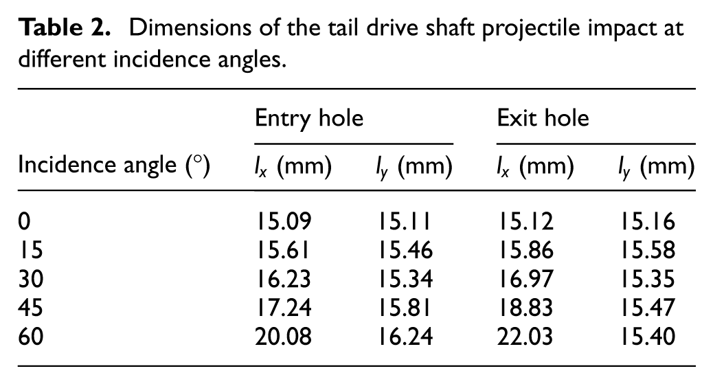
Dimensions of the tail drive shaft projectile impact at different incidence angles.
Dimensions of the tail drive shaft projectile impact at different radial offsets.

From Tables 2 and 3, it can be observed that the axial and radial dimensions of the damaged bullet holes are not entirely the same whether the projectile impacts at different incidence angles or radial offsets. Combining the information with the morphologies presented in Figures 4 and 5, it is concluded that with a gradual increase in incidence angle, the axial tearing damage becomes more severe, leading to the axial dimension of the damage holes gradually increasing. For incidence angles greater than 0°, the axial dimension of the damage hole is greater than the radial dimension. Conversely, as the radial offset gradually increases, the radial tearing damage becomes more severe, leading to the radial dimension of the damage holes gradually increasing, and the radial dimension of the damage hole is greater than the axial dimension.
In order to further describe the damage to the tail drive shaft due to projectile impact, the area of the bounding rectangle of the bullet hole is used in this paper as the damage area of the tail drive shaft. The magnitude of this damage area is then used as an indicator for assessing the degree of tail drive shaft damage after being subjected to projectile impact. The axial dimension and radial dimension are defined as the length and width, respectively. This definition of damage area is the closest approximation to the actual damage area. The relationship curves between the bullet hole damage area and different incidence angles and radial offsets are plotted and shown in Figure 7.
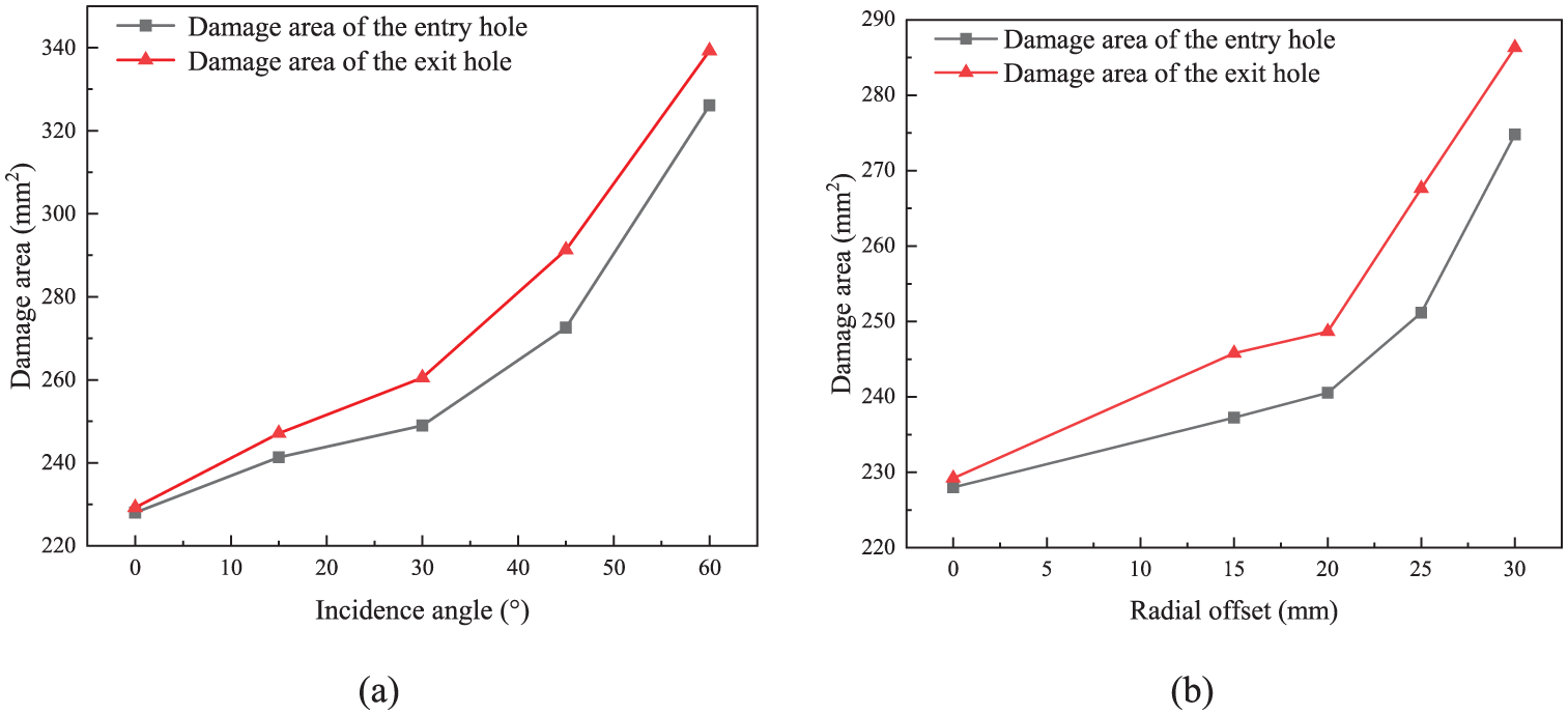
Relationship between damage area and different impact conditions: (a) damage area at different incidence angles and (b) damage area at different radial offsets.
As observed in Figure 7, with the increase of incidence angle and radial offset, the area of the damaged bullet hole gradually increases, and the exit hole area is larger than that of the entry hole. Combining this with the analysis of the projectile impact conditions, when impacting at different angles, there is a gradual expansion in the contact area between the projectile and the tail drive shaft as the incidence angle increases, as the projectile continues to penetrate the tail drive shaft, the impacted point is further compressed, leading to the bullet hole to expand and the damaged area to gradually increase. On the other hand, for different radial offsets, with an increasing radial offset, the projectile impact condition progressively approaches the trimming damage mode, and the damage area also gradually increases. The projectile impact conditions are altered after the external shaft impact due to the influence of external ballistic characteristics, specifically, the dynamic state of the projectile changes as it penetrates the tail drive shaft, which causes the exit hole area to be larger than the entry hole area. 15 In other words, as the incidence angle and radial offset increase, the degree of the helicopter tail drive shaft damage from projectile impact becomes more severe, and the degree of damage to the exit hole is greater than that of the entry hole.
Figures 4 and 5 show that the entry and exit bullet holes are similar to an elliptical shape. To facilitate the establishment of finite element models for subsequent research, such as predicting the crack propagation life of tail drive shafts, the damage morphology formed by projectile impacts at different angles of incidence and radial offsets has been geometrically simplified in this paper. The elliptical area formula is selected for simplification, which is similar to the morphology, as shown in equation (3).

Where
Dividing the axial and radial dimensions in Tables 2 and 3 by two, as described by equation (3), yields the respective semi-axes of the elliptical shapes. These are presented in Tables 4 and 5, rounded to two decimal places.
Simplified major and minor axis radii of the projectile hole on the tail drive shaft under different incidence angles.

Simplified major and minor axis radii of the projectile hole on the tail drive shaft under different radial offsets.

Since the bullet hole morphology resembles a standard circle under 0° impact and 0 mm radial offset impact, the simplification of the morphology to a circle using the equivalent area method has been considered in this paper. In this case, the equivalent radius of the ellipse is used as the radius of the simplified circle. The equivalent radius is defined as the radius of a circle with the same area as the ellipse, as shown in equation (4).

Where
Substituting the simplified elliptical area for 0° impact and 0 mm radial offset impact into equation (4), the simplified circular equivalent radii of the entry and exit holes under 0° impact and 0 mm radial offset impact are obtained as 7.56 mm and 7.57 mm, respectively.
Based on the above, the morphology of the damaged bullet hole is simplified as follows: the entry and exit holes resulting from 0° incidence and 0 mm radial offset incidence will be simplified as circular holes. Under other operation conditions, when impacted at incidence angles of 15°, 30°, 45°, and 60°, the entry and exit holes will be simplified as elliptical holes with a semi-major axis taken as half the axial dimension and a semi-minor axis taken as half the radial dimension. When impacted at radial offsets of 15, 20, 25, and 30 mm, the entry and exit holes will be simplified as elliptical holes with a semi-major axis taken as half the radial dimension and a semi-minor axis taken as half the axial dimension. The bullet hole simplification is shown in Figure 8.

Simplified schematic diagram of bullet hole geometry: (a) 0° and 0 mm, (b) other incidence angles, and (c) other radial offsets.
In the process of modelling using the simplified method of morphology, when the projectile impacts in the middle of the tail drive shaft at varying incidence angles, the center of the entry hole is the impact point, and the center of the exit hole is determined according to the tangent function of the incidence angle and the outer diameter of the tail drive shaft. When the projectile impacts the center of the tail drive shaft with different radial offsets, the center of the bullet hole is the impact point.
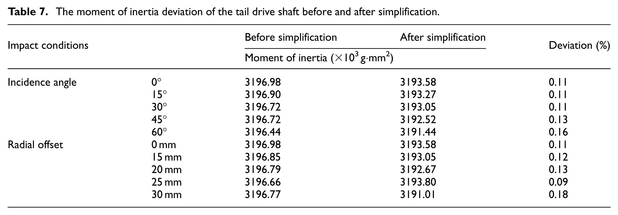
To ensure the reliability of the subsequent simplified numerical model, dynamic similarity is used to verify the rationality of the above simplification of the morphology of the bullet hole. Based on the aforementioned geometric similarity, the deviation between the residual mass and moment of inertia of the tail drive shaft after projectile impact and those of the simplified tail drive shaft is taken into consideration. The mass, the moment of inertia around the axis through the center of mass, and the centroid coordinates of the tail drive shaft under each impact condition are obtained through finite element analysis. According to the parallel axis theorem,17,18 the moment of inertia of the tail drive shaft around its axis is calculated. The masses and moments of inertia before and after simplification are listed in Tables 6 and 7. From Tables 6 and 7, the maximum deviation of mass of the tail drive shaft before and after simplification is 0.18%, and the maximum deviation of moment of inertia of the tail drive shaft before and after simplification is 0.18%. The deviation for both being less than 0.20% indicates that the proposed simplified model is reliable.
The mass deviation of the tail drive shaft before and after simplification.

The moment of inertia deviation of the tail drive shaft before and after simplification.
Numerical simulation of crack propagation in the damaged tail drive shaft
Co-simulation workflow and analysis model
As shown by the preceding projectile impact dynamics simulations, the tail drive shaft exhibits both burrs and cracks in the impacted region. Under subsequent operational loads, this damaged area becomes a fatigue source, prone to fatigue crack propagation, ultimately culminating in its fatigue fracture failure. To investigate the remaining fatigue performance of the helicopter tail drive shaft under different impact conditions, the crack propagation life law of the helicopter tail drive shaft is investigated through the co-simulation of ABAQUS and FRANC3D software. The proposed bullet hole simplification method is adopted to simplify the modelling of the damaged tail drive shaft under each impact condition. The specific co-simulation workflow is shown in Figure 9.

Flow chart of the ABAQUS and FRANC3D Co-simulation workflow.
Initially, stress analysis is performed in ABAQUS on the simplified-geometry tail drive shaft under load, as shown in Figure 10(a). The material properties of 6061 aluminum alloy and boundary load are applied to the tail drive shaft. The tail drive shaft is selected to have the same structural parameters as in the projectile impact simulation model. The mesh in the crack propagation region is refined, while the mesh in the non-propagation region is coarsened. 31 The mesh elements are C3D8R hexahedral elements. Subsequently, stress analysis is carried out. After the analysis is completed, the model is imported into FRANC3D for meshing. Utilizing the embedded submodeling technique, the region with a dense mesh is treated as a local submodel that retains the boundary conditions and loads of the full model, and the local submodel is then used for crack propagation simulation.
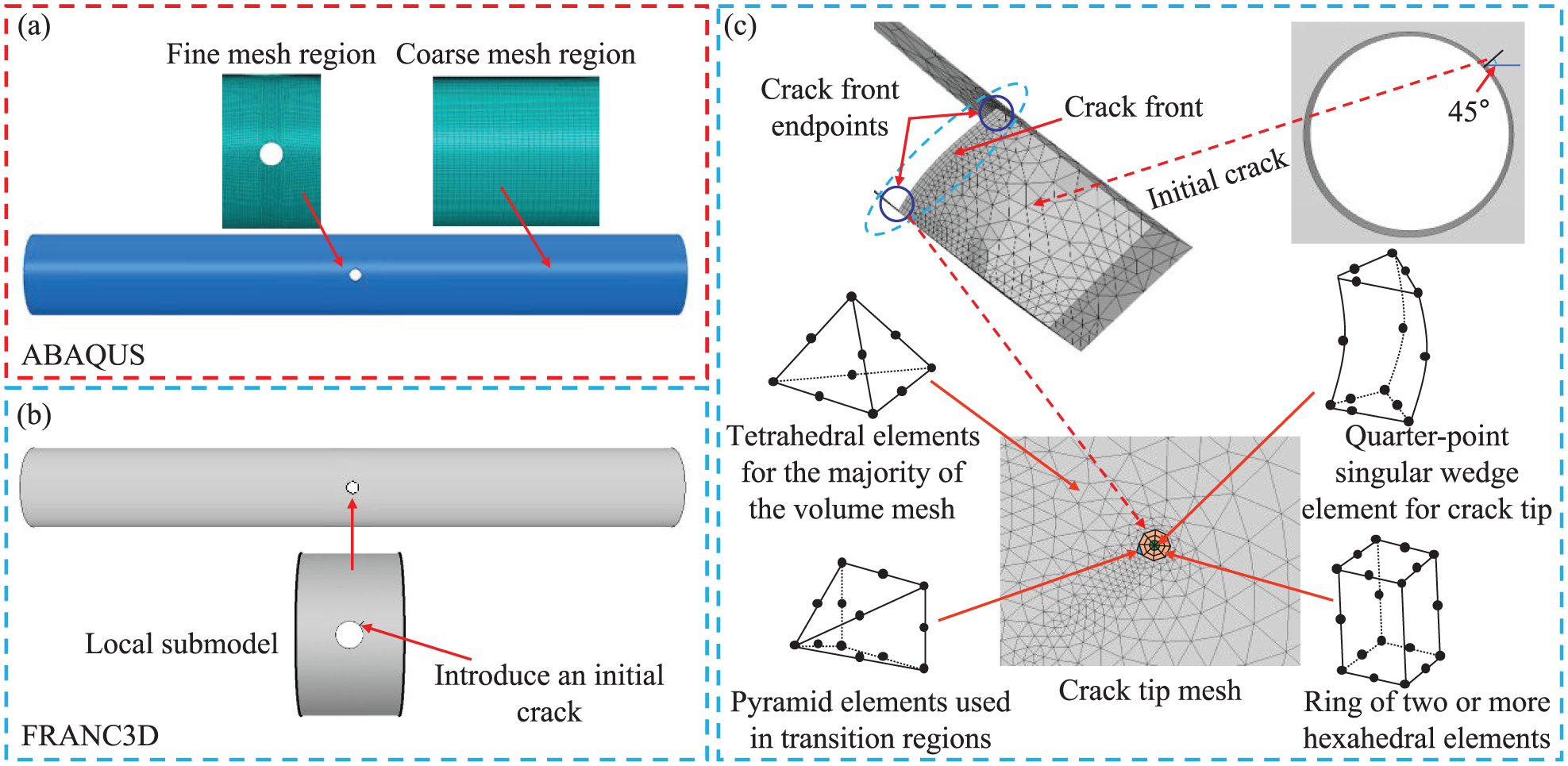
Crack propagation simulation model: (a) overall model stress analysis, (b) local submodel crack parameters, and (c) crack tip mesh element.
According to the relevant literature,20,21,32 the crack propagation in the tail drive shaft under torsional loading propagates at an angle of 45° to the axis. Therefore, an initial crack oriented at 45° to the axis is introduced, as shown in Figure 10(b). FRANC3D has an adaptive three-dimensional crack mesher. The imported mesh model undergoes geometric reconstruction, and the model is re-meshed when an initial crack is introduced, including both surface and volume meshing. 33 A generalized cylindrical tube-shaped element template with controlled size and shape is placed at the crack front, with the crack front being the axis of the cylindrical tube. This template consists of three layers of structured annular elements. Quarter-point singular wedge elements are located immediately adjacent to the crack front to capture the tip singularities, surrounded by concentric rings of hexahedral elements. The non-crack propagation region is composed of tetrahedral elements. Pyramid elements are used for the transition between hexahedral and tetrahedral elements to provide compatibility between the two, as shown in Figure 10(c). This mesh arrangement enhances the accuracy of stress intensity factor (SIF) calculations. Furthermore, by utilizing an adaptive meshing technique to re-mesh the local submodel, the three-dimensional crack mesh is adaptively updated during the crack propagation. After the mesh is generated, the local submodel is merged with the remaining model, and stress analysis is performed again in ABAQUS. The SIF is obtained for each propagation step, and the analysis continues until the predefined crack propagation termination criterion is met. Crack propagation fatigue life prediction is then obtained based on the crack extension increment and the SIFs, and then combined with a crack propagation rate equation.
Method for fatigue crack propagation calculation
The SIF is employed to describe the stress field intensity at the crack tip. The larger the value of the SIF, the greater the stress near the tip, and the higher the probability of crack propagation. The SIF is commonly represented by the symbol

Crack propagation modes.
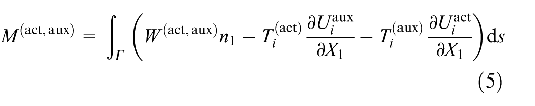
The M-integral 37 in FRANC3D fracture analysis software is employed in this paper to calculate the SIF at the crack tip during crack propagation in the tail drive shaft. The M-integral serves as a method to determine the SIF by utilizing the stress and displacement fields at the crack tip. 38 Furthermore, through a path-independent integration, it efficiently calculates the energy release rate, predicts crack extension, and avoids the crack tip singularity problem. 39 Meanwhile, it is numerically similar to the J-integral, which provides higher solution accuracy. The M-integral is expressed as:
Where
In finite element analysis of three-dimensional crack propagation, formulating the M-integral as an equivalent domain integral yields more accurate results. The expression is presented as follows:

Where
The relationship between the M-integral and the SIF is given by:

Where
Utilizing the aforementioned M-integral method, the SIFs at nodes along the crack front are computed and analyzed for the tail drive shaft subjected to projectile impact at a 0° incidence angle. The variation rule of the SIF after normalization of the crack front is obtained as illustrated in Figure 12. In Figure 12, three types of SIFs are present during crack propagation in the tail drive shaft, and the value of

Three-dimensional SIF variation rule along the crack front: (a)
The fatigue crack growth rate is governed by factors such as the SIF, stress ratio, material properties, and environment. Classical crack growth rate models include the Paris formula, 40 Walker formula, 41 Forman formula, 42 NASGRO formula, 43 etc. The Paris formula is one of the most fundamental and widely used models for describing the fatigue crack propagation behavior of materials, due to its simple form and wide applicability. The Paris formulation reveals the dynamics of crack propagation in materials, emphasizes the role of the SIF range in crack expansion, and provides a quantitative method for predicting fatigue life.
The Paris formula is adopted in this paper to characterize the crack growth rate in the helicopter tail drive shaft, 2 as expressed below:

Where
Integrating the Paris formula yields the fatigue life,

Where
According to the previous analysis, when the tail drive shaft is in crack propagation,

Therefore, the equivalent SIF range is expressed as:

Many criteria are available for predicting crack propagation direction, such as the maximum tensile stress criterion, the maximum energy release rate criterion, the minimum strain energy density criterion, etc.
46
These criteria utilize stress or energy fields to determine the direction of crack propagation. The maximum tensile stress criterion
47
is chosen for determining the crack propagation direction in this paper. Figure 13 illustrates that when

According to the direction criteria:

The cracking angle is expressed as follows:

In FRANC3D, the 3D crack front is represented as a spatial curve composed of a set of extrapolated nodes, 31 as shown in Figure 14. The crack front is discretized into several points, the new position of each point is calculated after crack propagation and the updated crack front is smoothly fitted with a polynomial or spline curve. The magnitude of the SIF at the crack tip points along the 3D crack front varies depending on the location of these tip nodes.

Crack propagation cracking angle.

Three-dimensional crack front fitting process.
For the extension increment of the median stress intensity factor node on the crack front, a value typically ranging from 15% to 20% of the crack characteristic size is used. The selected crack extension increment is along the median SIF node on the crack front in this paper and is kept constant at 15% of the initial crack size. The extension increments for nodes at other locations along the crack front can be obtained according to the equation (15):

Where
Analysis of results
Based on the above bullet hole simplification method, simplified models are created and used for crack propagation analysis. In this paper, a torque load of 1577 N·m is applied to the tail drive shaft for stress analysis, 22 as illustrated in Figure 15. Based on the impact condition analysis and supported by Figure 8, the differing tip positions of the elliptical bullet holes, which are formed by projectile impacts at varying incidence angles and radial offsets, lead to variations in the stress concentration phenomena under applied torque. Stress analysis indicates that symmetric, petal-shaped stress distributions form around bullet holes. Elliptical bullet holes exhibit more severe stress concentration than circular holes, with stress values consistently higher for elliptical holes. Moreover, elliptical impact holes generated by radial offset exhibit higher stress values than those formed by incidence angle impact. The initial crack initiation direction was further determined by analyzing the direction of the maximum principal stress at the bullet hole. Figure 16 illustrates the stress distribution in the tail drive shaft and the node location of the maximum principal stress when the projectile impacts at 0°. According to relevant literature, cracks tend to nucleate in areas with stress concentration, and the stress analysis presented in Figure 16 reveals that the damaged tail drive shaft exhibits stress concentration at the edge of the bullet hole,21,32 and the maximum principal stress is located at the exit hole. Cracks generally start from the exit hole and propagate at an oblique angle of 45° relative to the axis, which corresponds to the direction of maximum principal stress indicated by the red arrow. 21 Therefore, an initial length crack of 1.5 mm at a 45° angle to the axis is introduced at the edge of the exit hole on the tail drive shaft. 48 Subsequently, a cyclic torque load with a stress ratio of 0.1 is applied for crack propagation analysis.

Stress distributions under different impact conditions.

Stress analysis of the tail drive shaft at the 0° projectile impact.
Crack propagation direction is predicted using the selected direction criteria. With the selected specific extension increment, the crack tip position for the next step is calculated, forming a new crack model. With continued crack propagation, the aforementioned steps are repeated, ultimately generating the crack propagation path, as illustrated in Figure 17. Figure 17 illustrates that crack propagation in the tail drive shaft exhibits directionality and maintains a relatively regular path. This behavior is governed by the stress field, which dictates that the crack tip consistently extends along the direction of the maximum principal stress.

Fatigue crack propagation paths of the tail drive shaft under different impact conditions.
The propagation termination condition is set at a crack length of 9.5 mm. The .odb files generated at each crack propagation step were opened in ABAQUS. Stress contour plots were then plotted and analyzed to visualize the stress distribution at the crack tip. By obtaining the relationship between the SIF for each propagation step and crack length along the propagation path and combining the relationship with a crack growth rate formula, the fatigue life of the tail drive shaft due to crack propagation under specific stress ratio torque loading can be determined. The stress field at the crack tip during the final propagation step is plotted in Figure 18. The crack propagation life of the damaged tail drive shaft after the initial crack propagated to 9.5 mm under projectile impact is presented in Figure 19. From a combined analysis of Figures 15 and 19, stress values at elliptical bullet holes are consistently higher than those at circular bullet holes. Furthermore, radial offset impacts result in higher stress values compared to impacts at the incidence angle. This elevated stress directly leads to a greater SIF during crack propagation, consequently resulting in a faster propagation rate and a reduced crack propagation life. Figure 19(a) indicates that the crack propagation life of the damaged tail drive shaft tends to decrease as the incidence angle of the projectile impact increases, and the shortest life is at an angle of incidence of 45°, which is 21.8% less than at an incidence of 0°. From Figure 18, the shortest crack propagation life occurs during 45° impact, primarily because the stress field at the crack tip along the crack propagation path is progressively higher than that observed during 60° impact. This higher stress level accelerates the propagation rate, consequently leading to a significantly shorter crack propagation life compared to the 60° impact case. According to Figure 19(b), the crack propagation life of the damaged tail drive shaft gradually decreases as the projectile impact radial offset increases, and the shortest life is at a radial offset of 30 mm, when the life is reduced by 55.9% compared to a 0 mm radial offset impact.

Stress contours at the final crack propagation step.

Crack propagation life of the tail drive shaft under different incidence angles and radial offsets: (a) different incidence angles and (b) different radial offsets.
Conclusions
In this paper, finite element analysis of the projectile impact tail drive shaft and two-stage light gas gun experiments are conducted to obtain the damage characteristics of the tail drive shaft under different impact conditions. Based on geometric similarity, a simplified model of the tail drive shaft with bullet holes is established, the stress distribution phenomena around different bullet holes were analyzed, and the crack propagation life under two impact damage conditions is obtained through co-simulation finite element analysis. The conclusions of the research are as follows:
(1) As the incidence angles and radial offset of the projectile impacting the tail drive shaft gradually increase, axial and radial tearing damage to the tail drive shaft becomes more severe, resulting in an expansion in both the axial and radial dimensions of the damage hole, and the degree of damage to the tail drive shaft shows an increasing trend.
(2) Geometrically simplifying the damage morphology obtained from the impact dynamics model is achieved through the application of the ellipse formula and the equivalent area method. The impact damage morphology is simplified to circular bullet holes for 0° incidence angle and 0 mm radial offset, while it is simplified to elliptical bullet holes with varied tip positions for other angles and radial offsets.
(3) The incidence angle and radial offset impacts result in elliptical holes with different tip positions on the tail drive shaft, consequently leading to variations in the stress concentration phenomena generated under applied torque. Compared to circular bullet holes, elliptical ones demonstrate more pronounced stress concentration, and radial offset impact induces more severe stress concentrations than incidence angle impact, resulting in shorter crack propagation life.
(4) The crack propagation life of the damaged tail drive shaft declines as the projectile impact incidence angle and radial offset increase. The shortest life of the tail drive shaft is at a 45° incidence angle, which is 21.8% less than at 0° incidence, and the shortest life is found when the radial offset is 30 mm, with the life reduced by 55.9% compared to 0 mm radial offset impact.
The simplified morphological method and research conclusions presented provide a theoretical foundation for monitoring and damage assessment caused by projectile impact on the helicopter tail drive shaft.
Footnotes
Handling Editor: Douglas Bueno
Funding
The authors disclosed receipt of the following financial support for the research, authorship, and/or publication of this article: The authors gratefully acknowledge the project support from the National Natural Science Foundation of China (Grant No. 52275107) and the Hunan Provincial Science Fund for Distinguished Young Scholars (Grant No. 2024JJ2030).
Declaration of conflicting interests
The authors declared no potential conflicts of interest with respect to the research, authorship, and/or publication of this article.