
Abstract
Vehicle side impact accidents have high fatality rates due to limited deformation buffer and insufficient energy absorption of side structures. Simply enhancing structural stiffness and energy absorption characteristics may lead to increased occupant injury risk under side impact. To simultaneously improve side crashworthiness and occupant protection, this study proposes an origami-inspired honeycomb reinforced side structure and conducts systematic research. First, a full-scale finite element model of mobile deformable barrier (MDB) side impact has been established and verified with test data. Although besides impact simulation results reveal qualified structural crashworthiness, the occupant injury especially the head injury criterion (HIC15) is too high due to excessive intrusion of the vehicle body side structure. To address this problem, an origami-inspired honeycomb structure has been designed and embedded into the B-pillar and threshold beam. Then a meta-model based multi-objective optimization has been performed to improve the crashworthiness and occupant protection of the vehicle. Finally, crashworthiness comparison results demonstrate that the optimized reinforced structure significantly improved energy absorption and intrusion resistance, reducing occupant head and abdomen injuries.
Keywords
Introduction
With the rapid development of the automobile industry and the continuous increase in vehicle ownership, traffic safety has become a major public health and social issue that has attracted widespread attention from all sectors of society. 1 Among various types of traffic accidents, side impact accidents account for a significant proportion due to the high fatality rate and limited deformation buffer space under side impact. Improving the crashworthiness of the vehicle side structure and enhancing occupant protection performance under side impact conditions have become key research directions in the field of automobile safety engineering.2,3
The vehicle side structures including the B-pillar, threshold beam, and side inner panel serve as critical load-bearing components of vehicle doors, primarily safeguarding passengers during side impacts.4,5 Unlike the front and rear load-bearing structures, side structures are required to absorb maximum impact energy while minimizing passenger compartment deformation. In recent years, scholars have carried out extensive research on vehicle side crashworthiness and occupant protection, mainly focusing on structural optimization design and energy-absorbing material application.6–8 In the side impact, the lower part of B-pillar directly takes part in the impact of mobile deformable barrier (MDB). For the consideration of crashworthiness, this part should not be too stiff. 9 So the structural design of B-pillar requires the higher strength in upper region and the lower strength in bottom region. 10 Besides, it is proved that the stiffness of B-pillar is critical to resist the deformation. 11 Several design methods are proposed on the structural design. For instant, the method which combined topological optimization with shape optimization was used in the improvement of B-pillar performance to reduce the occupant chest injury in collision. 12 One-piece B-pillar structure was designed to provide side impact strength by the process of tailor-welded blanks. The thicknesses of different regions in B-pillar were optimized by using support vector regression (SVR) and the weight of B-pillar was reduced by 27.64%.13,14 For the threshold beam, the optimal design mainly focus on the cross-sectional shape and material thickness. Chahardoli 15 incremented the energy absorption capacity of the beam by creating a non-uniform cross-section with a cosine function at the upper part of the beam. Researchers compared different profiles for the threshold beam, three gages, and three different materials and analyzing the static and dynamic behaviors in the event of a side impact.16–18 Inspired by the stability inherent in triangular configurations, Xu et al. 19 introduced an octagonal self-similar hierarchical honeycomb by integrating multiple triangles into a hierarchical system within an octagonal framework. Cai and Deng 20 developed four novel hybrid honeycomb structures by combining different honeycomb configurations and designing new subunits through modifications to the unit cell geometry. The results indicated that the symmetric arrangement strategy can enhance the impact resistance of the honeycomb structure. On basis of above research, a conclusion can be achieved that the thin-walled beam with multi-cross-section outperforms the original simple section beam in specific energy absorption and impact force efficiency.21,22 However, most of the existing studies focus on the optimization of a single component, and there is a lack of integrated optimization design for the entire side structure system composed of the B-pillar, threshold beam, and side inner panel, which makes it difficult to achieve the optimal overall crashworthiness of the side. In addition, improving the energy absorption characteristics of the vehicle side structures does not directly enhance the occupant protection under side impact scenario. Conventional impact-resistant parts endow the vehicle with sufficient stiffness and strength to ensure the structural integrity of the vehicle body during a side impact. However, in terms of occupant protection, excessive rigidity may elevate the risk of occupant injury.
Over the years, the inner-filled reinforced structures have been suggested to improve the structures crashworthiness. Mohsenizadeh et al. 23 revealed that the foam-filled square tube presented 16.9% higher specific energy absorption than the hollow tube. Zhang et al. 24 studied the crash performance of sacrificial cladding with graded foam-filled structures, and found that foam-filled structures can greatly affect a vehicle’s crashworthiness. Yan et al. 25 embedded a cellular structure into a corrugated structure to enhance the crashworthiness capacities and reduce the initial crushing force. The results have shown that the filled corrugated structure demonstrated a 17.94% lower load fluctuation and a 6.69% higher crushing force efficiency. Qian et al. 26 concentrated on the design of space-filling multicellular structures utilizing multiple filling strategies. Further research indicated that the integration of the three strategies facilitates the design of structures specifically tailored to meet diverse application requirements.
Inspired by this concept, a novel origami-inspired honeycomb structure has been designed and adopted to reinforce the vehicle side structure for vehicle crashworthiness and occupant protection. The rest of this paper is organized as follows: Section 2 introduces the establishment and verification of the full-scale vehicle simulation model, including the modeling process of the vehicle body, MDB, and occupant restraint system, as well as the model verification. Section 3 analyzes the crashworthiness of the original vehicle side structure under MDB side impact, including structural dynamic response, key component deformation, and occupant injury evaluation. Section 4 focuses on the design and multi-objective optimization of the origami-inspired honeycomb structure, and embeds it into the B-pillar and threshold beam to improve the crashworthiness and occupant protection of the vehicle. Section 5 summarizes the main research conclusions of this study.
Full-scale modeling for vehicle crashworthiness analysis
In this section, a full-scale modeling for vehicle crashworthiness analysis has been built in LS-DYNA, including the full vehicle body model, mobile deformable barrier (MDB) model and occupant restraint system model. Subsequent verification of the built models has been conducted with reference to the side impact test standards established by the National Highway Traffic Safety Administration (NHTSA).
Vehicle body modeling
The finite element (FE) model employed for side impact analysis in this study is derived from a physical Toyota Yaris Passenger Sedan. This vehicle model has a gross weight of 1115 kg and encompasses 786 distinct components. To capture structural responses accurately, component-specific element types have been adopted. Belytschko-Tsay (BT) reduced-integration thin shell elements have been adopted to simulate the stamped steel parts, as they are well-suited for structures with thin-walled geometric characteristics. For three-dimensional (3D) components such as pedestals, eight-node solid elements with one-point reduced integration have been employed. A mesh sensitivity analysis has been performed to determine the optimal mesh size that balances simulation accuracy and computational efficiency. Five groups of mesh schemes with varied element sizes of 5, 8, 10, 15 and 20 mm have been designed and compared. The comparison shows that when the element size is increased from 10 to 15 mm, the maximum deviation of the accuracy indicators including the hourglass energy increases to an unacceptable value of 8.8%. Thus, the optimal mesh size of 10 mm has been selected for the vehicle body model in this study. The complete model comprises a total of 997,104 elements and 970,137 nodes, as shown in Figure 1. To guarantee mesh quality, triangular and tetrahedral elements are limited to no more than 5% of the total element count.

The vehicle finite element model.
Corresponding materials and their constitutive models including the elastic-plastic constitutive model and the rate-dependent elastic-plastic constitutive model have been calibrated against experimental data to match real-world mechanical behaviors to reflect dynamic response under side impact, as shown in Figure 2. The elastic-plastic model is mainly applied to the vehicle body steel plate like DC04, SPH440 and H340LA, which is the main load-bearing component of the vehicle. The model parameters include the strain rate coefficient C of 0.0015 s−1 and plastic strain failure criterion εf of 0.22. Under the impact simulation, the steel plate has low strain rate sensitivity, and its mechanical properties are mainly dominated by elastic-plastic deformation, so the elastic-plastic model can accurately describe its mechanical response.

Stress-strain curves of the main vehicle body materials: (a) DC04, (b) SPH440, (c) QSTE420 and CVTC and (d) H340LA.
The rate-dependent elastic-plastic model (Johnson-Cook model) is adopted for the dummy’s head and pelvis soft tissue as well as the vehicle’s energy-absorbing steering column like QSTE420 and CVTC. The model parameters include the strain rate coefficient C of 3.2 s−1, strain rate sensitivity coefficient m of 0.11 and Johnson-Cook failure criterion σf of 26 MPa. These components are sensitive to strain rate changes under impact load, and their deformation and failure characteristics are closely related to the strain rate, so the rate-dependent model is required to ensure the accuracy of simulation results.
Mobile deformable barrier (MDB) model
In this paper, by referring to the NHTSA test standard, the side impact has been performed on the driver side using the mobile deformable barrier (MDB) model which has the impactor and the trolley. This MDB system comprises two core components: an impactor and a trolley. Specifically, the impactor features a crushable section mounted on the front of the MDB, while the trolley is a wheeled frame engineered to travel along its longitudinal axis during the impact event. As depicted in Figure 3, the finite element (FE) model of MDB has been built in accordance with the NHTSA test standard, consisting of 120,012 elements and 141,192 nodes. The mass of the MDB model is set as 970 kg, and the center of gravity is 1000 mm backward from the front axle, 0 mm from the transverse center line, and 500 mm from the ground.
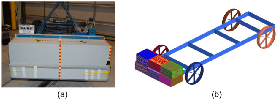
The models of mobile deformable barrier: (a) real model and (b) FE model.
Occupant restraint system modeling
EuroSID II dummy model
Among the various dummy models developed for side impact assessment, the European Side Impact Dummy II (EuroSID II) has emerged as a widely adopted standard, particularly in European New Car Assessment Programme (Euro NCAP). Its design is tailored to represent the 50th percentile adult male, making it suitable for evaluating occupant protection in passenger cars. Thus, the EuroSID II dummy model illustrated in Figure 4(a) has been integrated into the full-vehicle side impact model in this study. The EuroSID II dummy model features a modular design that mimics key human body segments, including the head, chest, abdomen, pelvis, and lower extremities (Figure 4(b)). Each segment is engineered to replicate the stiffness, mass distribution, and rotational properties of human anatomy, ensuring accurate transmission of impact forces during side collision events.

EuroSID II dummy model: (a) whole view of dummy and (b) measuring points of dummy injury.
Seatbelt model
For the seatbelt system, it has been modeled as a multi-body dynamic webbing model to replicate its load-bearing, energy-absorbing, and occupant-restraining behaviors during collision. As shown in Figure 5, a three-point retractable seatbelt has been modeled by using one-dimensional (1D) beam elements for the retractor and two-dimensional (2D) shell elements for the webbing. The webbing material is polyester and its material parameters include that the density is 0.82 g/cm3, the elastic Modulus is 8.8 GPa, the energy absorption coefficient is 0.7.

Seatbelt model.
Side airbag model
The side curtain airbag system has been modeled and integrated into the vehicle side panel within a spiral winding form to accurately simulate its deployment dynamics, inflation pressure distribution, and energy-absorbing interaction with the EuroSID II dummy, as shown in Figure 6. The physical geometric parameters of the airbag include the deployment area of 1.2 m2, the thickness of 0.3 mm and the trigger time of 10 ms. The material of the airbag is PA 66 with the density of 0.82 g/cm3, the elastic Modulus of 250 Mpa.

Side airbag model.
Integration of the occupant restraint system model
Further, the dummy model has been placed in the driver’s seat with a seated posture conforming to NHTSA specifications with hips laying at 750 mm above the ground, backrest angle of 25°, and arms resting on the armrests, as shown in Figure 7(a). This ensured that the dummy’s initial position matches real-world occupant seating behavior. Then a friction contact model with friction coefficient 0.3 has been applied to the seat cushion and backrest, preventing unrealistic sliding of the dummy during impact. A soft contact algorithm has been used to model the airbag’s deployment and interaction with the dummy head and thorax, ensuring accurate force transmission during inflation. To ensure accurate interaction with the EuroSID II dummy, contact pairs have been defined between the seatbelt webbing and the dummy’s thorax, pelvis, and shoulder segments. The integrated occupant restraint system model is illustrated in Figure 7(b).
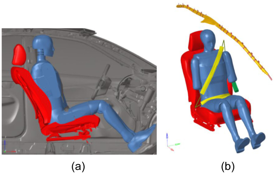
Occupant restraint system model: (a) positioning calibration of dummy model and (b) integrated model.
Vehicle crashworthiness analysis under MDB side impact
MDB side impact simulation and model verification
The MDB side impact simulation and analysis have been performed under the requirements of the NHTSA standard. As depicted in Figure 8, the MDB model is set to impact the vehicle model on the driver’s side at an initial velocity of 61.5 km/h. The angle between the MDB’s moving direction and the longitudinal center line of vehicle is set as 63°. The longitudinal center line of the moved barrier is aligned with the collision point of the test vehicle and perpendicular to the longitudinal center line of the experimental vehicle with the coincidence error of 25 mm. An automatic single contact type has been adopted to model the contact between the MDB and vehicle. The total simulation is set as 160 ms. The established model has been verified by comparing the simulation results with the real impact test results.

MDB side impact set: (a) NHTSA standard and (b) MDB side impact simulation model.
The comparison of structural deformation between the real test and the impact simulation is shown in Figure 9. The experimental tests have been conducted by NHTSA, with the corresponding results available on the official website. As observed in Figure 9, for critical side body structures including the B-pillar, rocker panel, and side inner panel which are primary load-bearing components during side impacts, the test and simulation results exhibit high consistency in deformation modes.

Comparison of structural deformation: (a) vehicle body and (b) MDB model.
In addition, the comparison of dummy posture between the real test and the impact simulation is shown in Figure 10. It can be seen from Figure 10 that both test and simulation show consistent posture trends. For the biomechanical responses of the dummy, the safety-related acceleration curves are further obtained and compared in Figure 11, including the head acceleration and pelvis center spot acceleration. It is illustrated that the simulation results are highly in accordance with the test results and that the moments of the acceleration peak values are approximately consistent. Specifically, the experimental result for the peak acceleration at dummy’s head is 41.58 g and the corresponding simulation result is 39.57 g, showing a relative error of 4.83%. For the peak acceleration at dummy’s pelvis center point, the experimental result is 80.55 g, the simulation result is 88.61 g, with a relative error of 9.10%. This quantitative result indicates that the deviation between the simulation results and experimental data in Figure 11 is small and within the acceptable range of related research. Collectively, the good agreement between simulation and physical test in structural deformation, dummy posture and biomechanical responses have been achieved, confirming the credibility of the established MDB side impact simulation model.

Comparison of dummy posture.
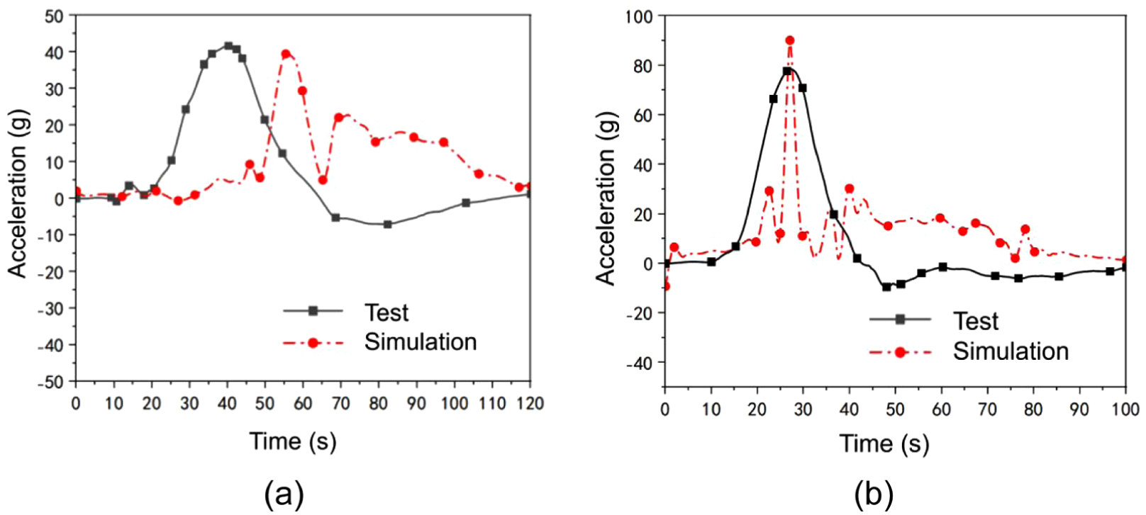
Comparison of the biomechanical responses of the dummy: (a) head acceleration and (b) pelvis center spot acceleration.
Vehicle dynamic responses
Figure 12 depicts the deformation program of the vehicle during the MDB side impact. It can be observed that significant deformation occurs in around the side structures including the side door, B-pillar and threshold beam. During the impact process, deformation first occurs at 10 ms in the left front and rear door areas. At 30 ms, the deformation gradually propagates backward, with slight deformation appearing in the front part of the side structure. When it reaches 40 ms, the deformation in the front part of the side structure intensifies further, and at the same time, the top of the passenger car starts to deform. Finally, at 70 ms, obvious deformation is observed in the rear door and the rear of the vehicle.
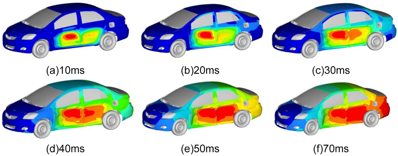
Deformation program of the vehicle during the MDB side impact: (a) 10 ms, (b) 20 ms, (c) 30 ms, (d) 40 ms, (e) 50 ms and (f) 70 ms.
To further evaluate the crashworthiness of cabin, four observation points have been built near the B-pillar, corresponding to the head, chest, abdomen and hip region in dummy model, as shown in Figure 13(a). Figure 13(b) shows the intrusion values of the four observation points. Analysis of the measurement data reveals that the intrusions at principal monitoring locations reach the initial peak values and then tend to increase until reaching the maximum value. Notably, the maximum intrusions recorded in the abdomen and hip region reach a critical level of 103 mm. For the dynamic structural intrusion at the measurement points of the vehicle B-pillar corresponding to the abdomen and hip of the 50th percentile adult male occupant, NHTSA FMVSS 214 explicitly stipulates a maximum allowable dynamic intrusion limit of 120 mm. The 103 mm maximum intrusion measured at the abdomen and hip regions in this study accounts for 85.8% of the 120 mm statutory limit, which is a typical near-threshold critical state, posing a significant threat to occupant safety.

The deformation of the B-pillar under side impact: (a) reference points for deformation observation and (b) intrusion values curves.
The deformation program of the threshold beam is show in Figure 14. It can be seen that an obvious bending deformation occurs in the middle area of beam, leading to the fold of middle floor. This may due to the weak bending resistance of the threshold beam.

Deformation program of the threshold beam: (a) 6 ms, (b) 28 ms, (c) 44 ms and (d) 80 ms.
Occupant injury responses
For the biomechanical responses of the dummy, the safety-related curves have been recorded in Figure 15. The corresponding evaluation indicators for passenger safety have also been calculated on basis of the obtained curves, and listed in Table 1. For the head acceleration (Figure 15(a)), it can be seen that the peak value occurs at about 60 ms, reaching a low permissible threshold. Considering the high HIC15 value of 568.87, the corresponding score for head safety is poor. For the pelvis resultant force (Figure 15(b)), at the initial stage of 38 ms, the resultant force reaches the first peak then shows a decreasing trend due to energy dissipation. At 64 ms, the resultant force reaches the maximum value of 2.9 kN, and then the side airbag deploys, leading the decrease of the resultant force. For the chest and abdomen acceleration (Figure 15(c) and (d)), a same trend can be summarized, exhibiting a typical dynamic response of rapid initial rise followed by slow decline. The maximum deflections for the chest and abdomen are 21.8 and 22.9 mm, which are below the indicators for high-performance evaluation. To conclude, the built restraint system provides good protection for the occupants. However, the occupant head injury criterion (HIC15) is relatively high due to excessive intrusion of the vehicle body side structure, which requires further improvement.

Biomechanical responses of the dummy: (a) head acceleration, (b) pelvis force, (c) chest deflection and (d) abdomen deflection.
Evaluation indicators for passenger safety.

Design and reinforcement of vehicle side structure
Design of honeycomb-filled vehicle side structure
To improve the occupant protection performance, a novel honeycomb reinforced vehicle side structure has been proposed in this work. The vehicle side structure is assembled by integrating an origami-inspired honeycomb structure into the hollow threshold beam and B-pillar. Inspired by the previous research, 27 an origami-inspired cell structure is designed with a double-layered, chiral and hyperbolic origami structure exhibiting easy-folding feature, as shown in Figure 16(a). The origami-inspired honeycomb is composed of a large number of cell structures through the periodic arrangement as shown in Figure 16(b). The main structural parameters of the cell structure include the total height of cell Hc, the thickness of cell wall tc, the length of top and bottom hexagons Lc, the length of middle hexagon Tc, and the angle between the middle hexagon projection and the bottom hexagon θ, as shown in Figure 16(a).

Design of origami-inspired honeycomb: (a) origami cell structure and (b) honeycomb structure.
As important parts of the vehicle side structure, the threshold beam and B-pillar must possess adequate strength and stiffness. However, excessive rigidity elevates the risk of occupant injury, as the impact force will be directly transferred to the occupant. Considering that the abdomen and hip intrusion of the original vehicle side structure is in such a critical state as discussed above, the reinforced structure have been arranged at the lower end of the B-pillar and the rear end of the threshold beam, which are the core load-bearing components corresponding to the abdomen/hip intrusion region, as shown in Figure 17. The side structures are modeled by integrating the outer panel, the origami-inspired honeycomb and the inner panel. The origami-inspired honeycomb is connected with the inner panel through adhesive bonding. The cohesive zone model (CZM) has been adopted to simulate the adhesive layer. The adhesive layer thickness is set as 0.2 mm. The material parameters for the adhesive model include the elastic modulus of 3.5 GPa, maximum shear tensile/shear strength of 32 MPa and fracture energy of 240 J/m2.

Reinforcement design of vehicle side structure: (a) the threshold beam and (b) the B-pillar.
Considering the engineering requirements of vehicle crashworthiness and lightweight design, PA6 has been selected as the core material. The material parameters include the density of 1.14 g/cm3, elastic modulus of 2.9 GPa and yield strength of 75 MPa. To accurately characterize the dynamic mechanical behavior of PA6, a polymer-specific constitutive model has been adopted with the strain hardening coefficient of 120 MPa, strain hardening exponent of 0.25 and strain-rate sensitivity coefficient of 0.012.
Structural optimization of honeycomb structure
The origami-inspired honeycomb structure in this study is an embedded energy-absorbing reinforcement component for the B-pillar and threshold beam. Considering the huge time-consuming of occupant protection simulation, we have optimized the intrinsic performance of the vehicle side structure which directly determine the energy absorption capacity and anti-intrusion performance of the vehicle and then verified the improvement effect of the optimized structure on occupant injury metrics. In general, it is infeasible to conduct optimization design of the energy-absorbing device, as certain parameters such as the specific energy absorption and the maximum crushing force have been shown to exert contradictory effects on performance indicators. Consequently, to obtain the optimal geometric parameter design of the origami-inspired honeycomb under side impact scenario, a meta-model based multi-objective optimization approach is implemented in this section. The main flowchart of the proposed approach is outlined as follows: mathematical formulation of the multi-objective optimization problem, meta-modeling via the polynomial response surface method, and optimization solution using the Multi-objective particle swarm optimization (MOPSO) algorithm.
Mathematical formulation
On the basis of the above-mentioned analysis results, the mean crushing force (MCF), the specific energy absorption (SEA) and the total mass (M) of the origami-inspired honeycomb under side impact are selected as the main optimization objectives. Three structural parameters tc, θ and Lc/Tc, have marked influences on energy absorption performance, and therefore they are adopted as the design variables in optimization modeling. Table 2 lists the variation range of design variables.
Design space of the design variables.

The goal of optimization design for honeycomb structure is to promote the energy absorption performance while the total mass is regulated in a moderate level. Thus, the multi-objective optimization problem can be defined as a constraint satisfaction problem, where the goal is to find a set of solutions that maximize SEA, MCF and minimize M. The mathematical model of this optimization problem is described as follows:

Meta-modeling
As stated in equation (1), the optimization process is performed on basis of specific values of the objective functions. Thus, we adopted meta-model technique herein to achieve the evaluations of the objective functions. Before constructing the meta-models, a design of experiment (DOE) process has been performed with a central composite design, and the results are listed in Table 3.
The results of DOE.

The polynomial response surface method, for its effectiveness and accuracy in high dimensional spaces and small sample size problem, is adopted in this work to construct the analytical models. On basis of the DOE results in Table 3, the meta-models for MCF, SEA and M are formulated as follows:

Additionally, the accuracy assessment for the meta-models of MCF, SEA and M have been performed on basis of the DOE data in Table 3. The assessment adopts the coefficient of determination R2 and root mean square error RMSE as the core evaluation indicators, and the results are summarized in Table 4. Theoretically, the lower value of RMSE present an accurate prediction. The coefficient of determination R2 varies from 0 to 1, and a value near 1 represents a highly precise prediction. Thus, it can be concluded from Table 4 that the constructed meta-models prove to exhibit good fitting accuracy.
Fitting accurecy evaluation indicators for the meta-models.

Multi-objective optimization
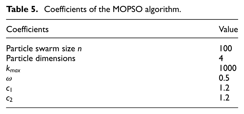
The multi-objective collaborative optimization problem tackled in this study essentially entails searching for a set of non-dominated solutions—namely the Pareto front. Numerous optimization algorithms for multi-objective problems have been developed in previous research, including evolutionary algorithms, ant colony optimization, genetic algorithms, and other approaches. Among these, the Multi-objective Particle Swarm Optimization (MOPSO) algorithm, inspired by the foraging behavior of birds, emerges as a prominent swarm intelligence optimization method. MOPSO is highly acclaimed for its well-distributed Pareto front and robust convergence performance. In this study, a typical MOPSO algorithm is employed to solve the constrained multi-objective optimization problem. Table 5 presents the corresponding coefficients pre-specified in the MOPSO algorithm.
Coefficients of the MOPSO algorithm.
The detailed optimization process has been implemented with about 120 iterations and approximately 55 min to converge to the desired results. The resulting Pareto front comprising 100 solutions. Clearly, the obtained Pareto front offers designers a set of optimal design facts to choose from according to specific practical requirements. From the viewpoint of the extremity for engineering application, depending on the Pareto front, two solutions are selected, characterized as the maximum SEA solution and the minimum M solution, as summarized in Table 6.
Optimal solutions for multi-objective optimization.
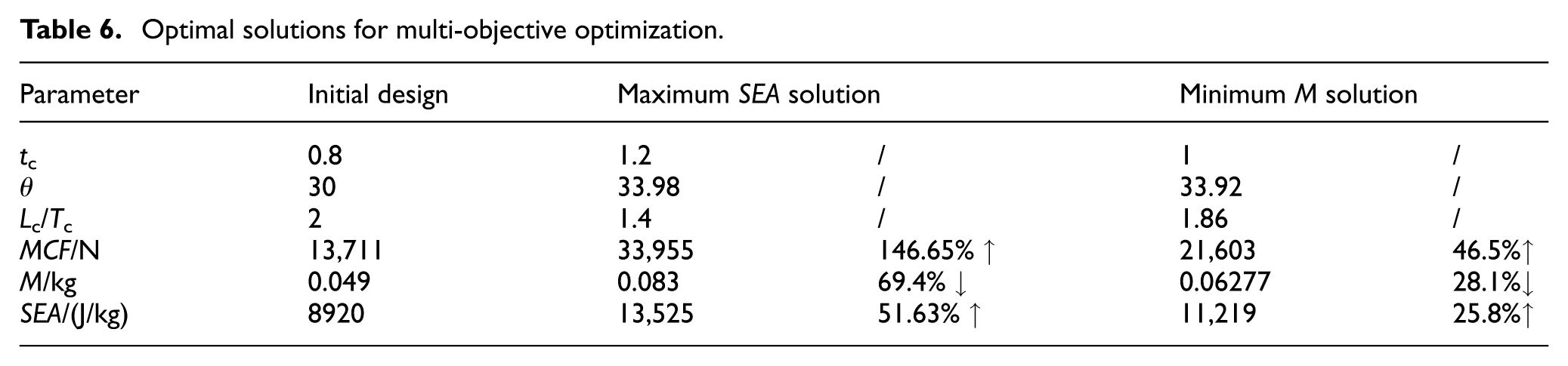
It can be seen from the results in Table 6 that the maximum SEA solution achieves significant improvements in multiple performance indicators: the mean crushing force increases from the 13,711 to 33,955 N, with an increasing rate of 147.65%; the specific energy absorption increases from 8920 to 13,525 J/kg, showing a growth of 51.63%; meanwhile, the total mass increases to 0.083 kg. In contrast, the minimum M solution exhibits a mass increase of only 28.1%, with improvements in the mean crushing force and the specific energy absorption of 46.5% and 25.8% respectively.
Crashworthiness analysis after reinforcement design
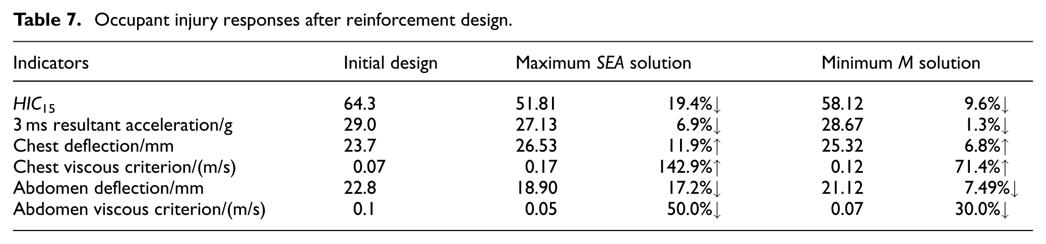
The crashworthiness analysis after reinforcement design has also been performed and the occupant injury responses are listed in Table 7. It can be concluded that when the threshold beam and B-pillar are filled with the origami-inspired honeycomb, the maximum SEA solution and the minimum M solution exhibit similar optimization effects on dummy injury values. The maximum SEA solution performs remarkably in reducing dummy’s head, abdomen and pelvic injuries but simultaneously aggravates chest injury. Compared with the initial design, the maximum SEA scheme’s reinforced components exhibit higher anti-deformation capacity, resulting in the impact force of the barrier being directly and rapidly transmitted to the occupant’s chest through the side structure, rather than being fully buffered by the gradual deformation of the structure. The concentrated transmission of impact force causes excessive chest deformation and viscous response, which may directly cause the increase of chest injury. In contrast to the maximum SEA solution, while the minimum M solution is less effective in improving head, abdomen and pelvic injuries, it results in a lower chest injury and delivers a more balanced overall performance. To summarize, the reinforcement design by integrating the origami-inspired honeycomb can provide a comprehensive improvement in occupant protection.
Occupant injury responses after reinforcement design.
Conclusions
This study focuses on improving the crashworthiness of vehicles and enhancing occupant protection under mobile deformable barrier side impact. A comprehensive research framework was established, including the development and verification of a full-scale finite element model, the design of an origami-inspired honeycomb reinforcement structure, multi-objective optimization of structural parameters, and crashworthiness evaluation after reinforcement. The key conclusions are summarized as follows:
The full-scale vehicle FE model has been constructed and validated against NHTSA side impact test standards. The simulation results show high consistency with physical test data in terms of structural deformation modes, dummy posture, and biomechanical responses. The results show that the occupant head injury criterion HIC15 is relatively high due to excessive intrusion of the vehicle body side structure, providing a clear direction for further improvement of the side structure design.
By proposing a novel honeycomb-reinforced vehicle side structure integrated with an origami-inspired honeycomb and conducting meta-model based multi-objective optimization, the optimized key structural parameters (tc,
Through analyzing the two typical optimal solutions derived from the Pareto front of the multi-objective optimization, it was found that the maximum SEA solution achieves a 147.65% increase in MCF and a 51.63% increase in SEA, while the minimum M solution has a moderate 28.1% mass increase and balanced overall performance with smaller chest injury increments.
By adopting the origami-inspired honeycomb filling for the reinforcement design of the vehicle side structure, comprehensive improvements in occupant safety were achieved, with key injury indicators such as HIC15 and abdomen deflection significantly reduced. The research results offer a feasible technical approach for the crashworthiness design and optimization of vehicle side impact.
Footnotes
Handling Editor: Jianguang Fang
Funding
The authors disclosed receipt of the following financial support for the research, authorship, and/or publication of this article: The authors would like to thank the funding support from the National Natural Science and Foundation of China (Grant No. 52202444).
Declaration of conflicting interests
The authors declared no potential conflicts of interest with respect to the research, authorship, and/or publication of this article.