
Abstract
To combine the high transmission ratio of nutation drives with the non-contact power transfer of permanent-magnet gears, this paper proposes a novel radial meshing nutation magnetic drive system (RMNMD) and investigates its magnetic coupling mechanism and kinematic principle. First, an analytical model for the RMNMD output torque is established based on an equivalent-current magnetic-field model, incorporating coordinate transformations and Lorentz torque integration, and is numerically evaluated using the double Simpson’s 1/3 rule. Comparison with three-dimensional finite-element simulations in ANSYS Maxwell verifies that the model is suitable for torque prediction. Then, under engineering constraints such as a constant total amount of permanent-magnet material, a fitness-feedback-based dynamic inertia-weight particle swarm optimization algorithm (D-APSO) is developed to jointly optimize key magnet geometric parameters, including the central angle, length, thickness, and inner radius, with dual objectives of maximizing torque and minimizing overall volume. The results show a 4.82% increase in output torque, a 1.58% reduction in volume, and a 6.51% improvement in torque density. Moreover, compared with PSO and APSO, the proposed method achieves better overall performance and faster convergence. This integrated “analytical modeling–D-APSO optimization–simulation validation” framework enhances RMNMD torque density without increasing magnet usage, providing a reference for compact, high-torque-density nutation-based PM transmissions.
Featured application
This work focuses on nutation drives and magnetic gear transmissions. In the field of industry and new energy, due to its compact structure and large transmission ratio, nutation drive can be applied to robot joints to improve precision. With the advantages of non-contact and lubrication-free features, magnetic gear transmission is suitable for noise reduction and efficiency improvement in power transmission of new energy vehicles. Both provide efficient transmission solutions for intelligent manufacturing and green energy.
Introduction
The nutation drive, also referred to as a bevel gear nutation drive, represents an innovative mechanical transmission system derived from the principles of celestial planetary motion and the gyroscopic nutation effect. Substantial research by both domestic and international scholars on its theoretical underpinnings and structural configurations has demonstrated several intrinsic advantages, including a high transmission ratio, superior load-bearing capacity, and compact design. These attributes render the nutation drive a promising solution for high-precision transmission applications in various domains, such as industrial robotics, electric vehicles, and aerospace engineering.1,2
Permanent magnetic gears (PMGs), which utilize magnetic field modulation mechanisms, enable torque transmission via non-contact power transfer. This approach offers multiple engineering advantages, including lubrication-free operation, inherent overload protection, low vibration, and minimal acoustic emissions. Collectively, these features enhance the reliability, efficiency, and environmental adaptability of modern transmission systems.3–5
To integrate the performance benefits of nutation drives and PMGs, this study introduces a novel transmission concept: the radial meshing nutation magnetic drive (RMNMD). Compared with traditional structures such as radial flux permanent magnet gears (RFPMG) and axial flux permanent magnet gears (AFPMG), the core advantage of the radial meshing nutation magnetic drive (RMNMD) lies in its nutating motion principle, which enables a higher single-stage gear ratio. This effectively solves the problem of limited gear ratio in traditional magnetic gears when used in low-speed, high-torque applications. This system replaces the direct meshing of traditional gears with a staggered arrangement of N and S pole permanent magnet pole tiles (magnets). It preserves the high transmission ratio and high efficiency characteristic of nutation gear systems while possessing the non-contact transmission structural attributes of permanent magnet gears (PMGs). As a result, it achieves an efficient, smooth, and structurally streamlined power transmission method.
The most critical indicator determining the transmission performance of RMNMD is its magnetic torque density, denoted by
Although structural optimization studies specifically targeting nutation magnetic gears remain relatively limited, multi-objective intelligent optimization has become a key technology for improving the overall performance of related permanent-magnet electromechanical systems, such as permanent magnet synchronous motors (PMSMs). These studies aim to balance multiple competing objectives—such as efficiency, electromagnetic performance, volume, cost, and dynamic response—by optimizing either structural configurations or control parameters. In terms of structural parameter optimization, Ruzbehi and Hahn 8 proposed a global–local hybrid optimization method for the PMSM rotor and permanent magnets, which seeks to maintain high torque while significantly reducing torque ripple and cogging torque, thereby enabling a more lightweight structure. Hu et al. 9 presented an optimal design approach for improving the torque performance of a magnetorheological fluid brake–integrated PMSM (MRFB-I PMSM). In that work, a Bagging-based machine learning model was innovatively developed, the braking torque was converted into a constraint, and a constrained genetic algorithm (GA) was employed to optimize the torque characteristics, effectively addressing the issues of low computational efficiency and poor convergence in multi-objective optimization. Regarding control-parameter optimization, Chen and Li 10 and Chen et al. 11 applied intelligent optimization algorithms to tune the parameters of PMSM speed controllers. Specifically, Chen and Li 10 used the grasshopper optimization algorithm (GOA) to optimize the PI controller parameters, enhancing the rapidity and robustness of the system. Chen et al. 11 adopted an improved crested porcupine optimizer (CPO) to tune the parameters of an advanced active disturbance rejection controller (ADRC), achieving a better trade-off between response speed and overshoot while improving disturbance-rejection capability. Collectively, these state-of-the-art studies demonstrate that intelligent optimization algorithms provide an effective means for addressing complex, multi-objective, and multi-constraint optimization problems in permanent-magnet drive systems, and they offer a solid theoretical foundation and methodological reference for the structural optimization of RMNMD toward maximizing torque and minimizing volume.
Given the complexity of the RMNMD torque model, which involves multiple interrelated design variables, conventional single-variable control methods are insufficient for achieving global optimization. To address this complex optimization problem with multiple objectives and constraints, this study adopts D-APSO algorithm. The algorithm enhances optimization performance by adaptively adjusting the inertia weight, improving robustness, search efficiency, and convergence rate.12–14 The D-APSO algorithm can derive an optimal set of permanent magnet structural parameters, effectively enhancing the magnetic torque density of RMNMD. This enables it to increase output torque while reducing the form factor. The method not only provides a comprehensive solution for the advanced design of RMNMD but also offers a reference for the optimization of other types of magnetic gear transmission systems.
Transmission principle of radial-chapter-actuated magnetic gearing system
The nutation magnetic drive (NMD), grounded in the principle of magnetic coupling, introduces magnetic fields into the gear transmission system to enable contactless energy transfer and precise motion control. Based on the direction of magnetic interaction, NMD configurations can be broadly categorized into a radial meshing nutation magnetic drive (RMNMD) and a axial meshing nutation magnetic drive (AMNMD). Compared with AMNMD, the meshing mode of RMNMD is closer to that of traditional mechanical gears, making it easier to replace traditional gears and be integrated into existing mechanical architectures. The sketch of RMNMD structure is shown in Figure 1, and the finite element model (FEM) and structural parameters are shown in Figure 2.

Sketch of RMNMD structure: (1) input shaft, (2) gear box, (3) MG1, (4) MG2, (5) output shaft, (6) positioning pin, (7) nutation sleeve, (8) tile permanent magnet and (9) nutation angle.

The FEM of RMNMD: (a) main view, (b) top view and (c) single permanent magnet structure.
The magnetic coupling principle of the RMNMD is analyzed based on its FEM as illustrated in Figure 2. MG1 is composed of a nutating disk and PMG1 tile-shaped permanent magnets, which are spliced into a frustum structure. It is connected to the input shaft through an eccentric nutating sleeve, where the eccentric angle, denoted by φ, is the nutation angle. The taper of the frustum is equal to the nutation angle φ. MG2 is composed of a rotating disk and PMG2 tile-shaped permanent magnets, which are spliced into a cylindrical structure. The central line of the cylinder is the output axis. In the absence of external excitation, the permanent magnets with opposite polarities along the radial direction of MG1 and MG2 attract each other and remain aligned.
When the input shaft is driven by an external power source, the eccentric nutation sleeve begins to rotate. Due to the mechanical constraint imposed by a locating pin, MG1 is restricted to nutation motion rather than free rotation. Under the effects of system inertia and external loading, a relative displacement occurs between the permanent magnets on both sides of MG1 and MG2, resulting in a misalignment angle referred to as the slip angle α. At this stage, in addition to the mutual attraction between magnets of opposite polarities, there is also repulsion between those of identical polarities. The combination of these attractive and repulsive magnetic forces generates a dynamic “push–pull” interaction that drives MG2 to rotate. This rotational motion realizes radial nutation magnetic coupling and transmits power to the output shaft.
The transmission ratio of the RMNMD is related to the number of permanent magnets in the magnetic gears. Its transmission-ratio calculation is similar to that of a planetary gear train and can be obtained using the mechanism-conversion method. Let the number of permanent magnets in MG1 be PMG1 and that in MG2 be PMG2. The rotational speed of the input shaft is n H . Due to the locating pin, MG1 cannot rotate, so its speed is n1 = 0. The speed of MG2 equals the output shaft speed, denoted as n2. The kinematic transmission ratio is i. Then, we have:

According to the mechanism-conversion method, an additional angular speed-n H is applied to the entire mechanism, and the resulting changes in the rotational speeds of each component are listed in Table 1.
Changes in the rotational speeds of each component after applying the additional speed-n H .

Thus, the transmission ratio between MG1 and MG2 can be obtained as:

Substituting n1 = 0 into equation (2) yields:
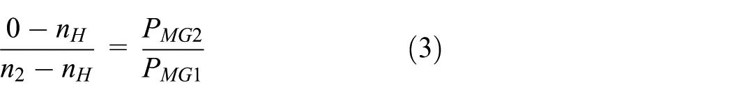
Combining equations (1) and (3) yields:

In order for the RMNMD to achieve a transmission ratio, the number of permanent magnets in PMG1 and PMG2 must not be equal. Furthermore, the smaller the difference between the two, the greater the resulting transmission ratio. To ensure the structural balance and operational stability of the magnetic gear, the number of permanent magnets is typically selected as an even number. Therefore, the transmission ratio reaches its maximum when PMG2 − PMG1 = ±2. In this study, PMG1 is configured with 32 magnets and PMG2 with 30 magnets. The structural parameters of the proposed RMNMD and their initial values are listed in Table 2, and their geometrical definitions are illustrated in Figure 2(a) to (c).
RMNMD structure parameters and initial values.

Deduction and analysis of RMNMD magnetic torque mathematical model
To obtain the magnetic torque density of the RMNMD, a magnetic torque
Derivation of the RMNMD output torque mathematical model
According to the equivalent current method in Lou et al., 6 starting from a radially magnetized tile-shaped permanent magnet, the three components of the magnetic flux density generated by a single tile-shaped permanent magnet in MG1, expressed in the cylindrical coordinate system (o s , r s , θs, zs), are given by:


where μ0 is the vacuum permeability; M is the magnetization intensity of the magnetic pole in MG1;
According to Figures 2 and 3, due to the presence of the nutation angle, coordinate transformations are required to convert the magnetic flux density from the cylindrical coordinate system of a single permanent magnet to the Cartesian coordinate system (o s , u s , v s , w s ), and then further transform it into the MG2 coordinate system (o′–x′, y′, z′). The transformation formulas are as follows:


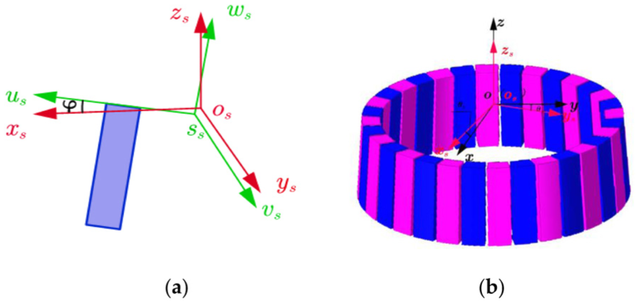
Spatial relationship between a single permanent magnet and MG1: (a) spatial relationship between the coordinate system of a single tile-shaped permanent magnet (s s , u s , v s , w s ) and the coordinate system of the sth permanent magnet in MG1 (o s , x s , y s , z s ) and (b) spatial relationship between the MG1 coordinate system (o, x, y, z) and the coordinate system of the sth permanent magnet in MG1 (o s , x s , y s , z s ).
The MG2 Cartesian coordinate system (o′–x′, y′, z′) and the cylindrical coordinate system (o′–r′, θ′, z′) can be converted into each other. The corresponding transformation formulas are as follows:


By combining the above equations, the radial component of the magnetic flux density generated by MG1 in the cylindrical coordinate system (o′–r′, θ′, z′) can be obtained as:

Where A
rs
,


The Lorentz force law is a physical method applied in magnetic systems to calculate the force and torque exerted on objects within a magnetic field.
15
According to classical electromagnetic theory, moving charges are subjected to forces in magnetic fields. For magnetic media, when the microscopic charged particles q inside them move in an external magnetic field

By considering the continuous distribution of charge as a volume current density

The moment of the differential force d

According to magnetic field analysis theory, for uniformly polarized magnets, permanent magnets can be represented by an equivalent distribution of volume magnetization current density

Assuming the magnetization is strictly radial, then
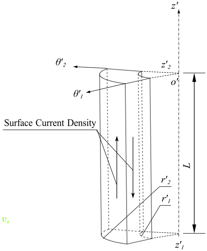
The orientation of permanent magnet in cylindrical coordinate system.
MG2 single tile magnet surface current density

Note. q represents any single tile-shaped permanent magnet in MG2.
By substituting the

Magnetic torque calculation based on Simpson’s integration method
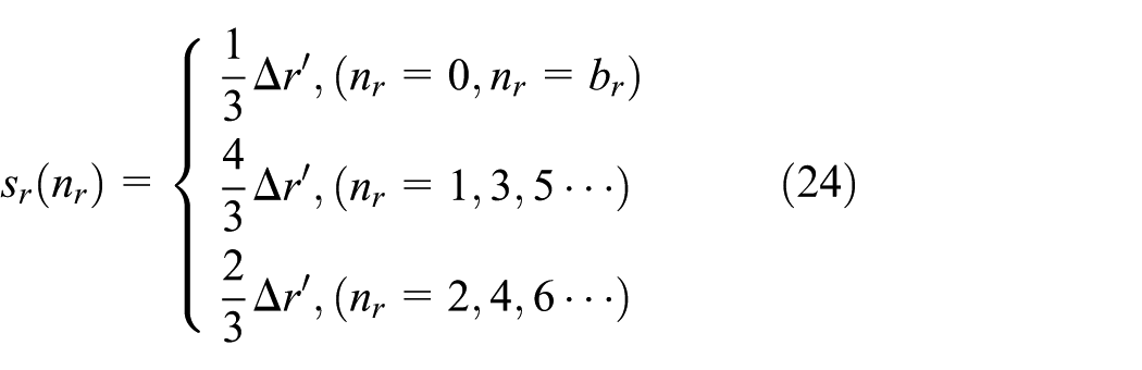
To perform the numerical calculation of the magnetic torque, a double Simpson’s 1/3 rule is used to carry out numerical integration over integration domains
The mesh points and the integration step sizes in domains

The standard form of Simpson’s 1/3 rule over one-dimensional interval

In the numerical computation, the step-size factors for domains

Then, equation (21) can be rewritten as:

From equation (26), we can see that the RMNMD magnetic torque T is mainly related to parameters such as α, L, r′ 1 , r′2, s, and PMG2.
Verification and analysis of the RMNMD magnetic torque mathematical model
Equation (26) represents the analytically derived mathematical model for the output torque of the RMNMD. This model can be implemented in MATLAB with the slip angle α as the variable. By substituting the initial parameters of the permanent magnets listed in Table 2, the numerical analytical curve depicting the relationship between the slip angle α and the magnetic torque T can be obtained, as shown in Figure 5.

Plot of magnetic torque T versus slip angle α.
As illustrated in Figure 5, the output torque T of the RMNMD exhibits a sinusoidal variation with respect to the slip angle α, with a periodicity of 24°. The maximum magnetic torque values appear at α = 6° and α = 18°, reaching a peak torque of 15.638 N·m.
To validate the accuracy of the proposed mathematical model for output torque, the MG2 is selected as the subject of study. In ANSYS Maxwell, the torque parameter T is assigned using the command path: (Maxwell) > (3D) > (Parameters) > (Assign) > (Torque). A full simulation is executed via the Analyze All function to obtain the magnetic torque values corresponding to various slip angles.
When the slip angle α is 6°, the magnetic flux density distribution and torque simulation interface of the RMNMD are depicted in Figure 6, where the simulated magnetic torque is found to be 15.771 N·m. Figure 5 clearly compares the MATLAB numerically evaluated curve based on equation (26) with the torque results obtained from Maxwell finite-element simulations. Within one period (

RMNMD flux density distribution and FEM data.
Optimal design of a single permanent magnet based on the D-APSO optimization algorithm
The RMNMD structure is composed of multiple single tile-shaped permanent magnets, and its overall performance and system reliability depend largely on the design quality of each individual magnet. Since the single tile-shaped permanent magnet involves numerous parameters related to both its geometric configuration and magnetic properties, with significant nonlinear coupling among these parameters, the design optimization problem is characterized by high dimensionality and multiple local optima. Traditional optimization methods typically exhibit slow convergence and a tendency to become trapped in local optima when addressing such complex problems. To overcome these limitations, this paper adopts D-APSO algorithm combined with a dynamic weighting strategy. This approach improves optimization accuracy and computational efficiency, while maintaining advantages such as a simple structure, ease of implementation, and low costs for tuning and maintenance. Furthermore, through dynamic adjustment of the search strategy, the algorithm can effectively escape local optima and accelerate global convergence, thereby providing an efficient and reliable optimization method for the design of single tile-shaped permanent magnets.17,18
D-APSO optimization algorithm model
In particle swarm optimization (PSO), the inertia weight w is a key parameter that governs the trajectories of particles and directly influences the search efficiency. Its regulation strategy plays a crucial role in maintaining a dynamic balance between global exploration and local exploitation. Traditional PSO typically employs a fixed inertia weight. However, when dealing with optimization problems involving complex constraints and multiple objectives, the objective function often exhibits dynamically varying spatial characteristics. Under such conditions, a fixed inertia-weight adjustment mechanism cannot effectively adapt to environmental changes, which may lead to reduced convergence speed, limited search capability, and a higher likelihood of being trapped in local optima.
To address these challenges, this paper proposes a dynamic inertia weight adjustment method based on fitness feedback, which is integrated into the adaptive PSO (APSO) algorithm. This method dynamically adjusts the inertia weight in real time according to the fitness trend of the particle swarm during the search process, thereby adaptively guiding the search behavior of particles. Consequently, the approach significantly enhances the algorithm’s global optimization capability and convergence stability. 19 The overall optimization procedure of the proposed D-APSO algorithm is illustrated in Figure 7.

Flow of D-APSO optimization algorithm.
In the conventional PSO algorithm, the distance and direction of a particle’s movement in the next iteration—that is, the particle position vector—are updated according to the following equations:


Where N denotes the swarm size; i is the particle index; D is the problem dimension; d is the dimension index; k denotes the iteration number; w is the inertia weight; c1 and c2 are the learning factors; m1 and m2 random numbers in (0, 1);
In the D-APSO optimization algorithm, particles are classified into feasible particles f ki and penalized particles f ci according to whether their fitness values satisfy the constraints. Feasible particles are those that meet the constraint conditions, and their number is denoted by N. Penalized particles are those that violate the constraints. The inertia weight w is then determined based on the average fitness f avg of the feasible particles f ki 20 :


where f denotes the current objective function value of a particle; w is the weight of the feasible particles f ki ; f avg is the current average fitness value of the particle swarm; fmin is the current minimum fitness value of the swarm; and wmax, wmin represent the maximum and minimum weight values, respectively.
Objective optimization function
This study aims to enhance the magnetic torque density of the RMNMD by optimizing the structural dimensions of the permanent magnets. To balance transmission performance and structural compactness, maximizing the magnetic torque T is defined as Objective 1, and minimizing the overall volume V is defined as Objective 2. A linear weighted-sum method is then employed to convert the two objectives into a single comprehensive objective. Considering the significant difference in orders of magnitude between torque and volume, the torque T0 and volume V0 corresponding to the initial design in Table 2 are selected as normalization factors. The objectives T and V are first nondimensionalized and then combined via weighted summation, where the weight coefficients are set to u1 = 0.7 and u2 = 0.3 to reflect the engineering preference of “torque priority with volume consideration.” The resulting comprehensive objective function is given in equation (31). In the ANSYS Maxwell simulations, NdFeB38 is adopted as the permanent-magnet material. Given its high cost, and to ensure that the optimization results genuinely reflect the structural improvements introduced by the D-APSO algorithm rather than superficial gains obtained by increasing magnet usage, the total amount (overall volume) of permanent-magnet material is constrained to remain constant during the optimization process. Under this constraint, the comprehensive objective function is used as the evaluation metric to achieve a rational trade-off between torque improvement and size reduction, thereby meeting the application requirements of nutation drive systems for miniaturization, high speed, and large transmission ratios. 21


Optimization variables
Considering the variables involved in the objective function, this study performs optimization under the conditions that the permanent magnet material, minimum air gap g = 0.5 mm, nutation angle φ = 4°, PMG1 = 32, and PMG2 = 30, and the slip angle αmax = 6°. The following parameters are selected as the optimization variables:

Constraints
Based on the transmission characteristics of the RMNMD, transmission ratio requirements, and the objectives of the optimization function, the following constraints are established:
1. Single permanent magnet non-interference constraint:

2. Movement constraints:
To ensure the reliability and stability of the RMNMD transmission system, the inner diameter of the MG1 must be greater than the sum of the outer diameter of the MG2 and the air gap, as expressed by:

3. Economic constraints:
Under the dual premise of guaranteeing both transmission performance and cost-effectiveness, the volume of permanent magnet in the RMNMD is constrained to remain constant, that is:

4. Single tile permanent magnet size constraints:
To prevent the size range of permanent magnets from becoming excessively large, which could negatively impact the convergence of the D-APSO optimization algorithm, the following empirical size constraints are applied:
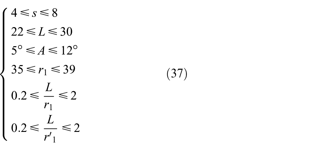
5. Maximum outer diameter constraint:
The optimization must ensure that the RMNMD meets performance standards without exceeding the spatial limitations, thereby operating within the designated spatial envelope and avoiding interference with other mechanical components or structures. Consequently, the maximum outer diameter rmax of the RMNMD is limited by:

Optimization results and verification
Algorithm validation
To verify the effectiveness and robustness of the proposed D-APSO, the classical multimodal benchmark function Schaffer F6 is selected as the reference test case for comparative experiments. 22 The mathematical expression of the Schaffer F6 function is given in equation (39), and its global minimum is 0. Since this function contains a large number of local minima, it can effectively evaluate the capability of swarm-intelligence algorithms to balance “global exploration” and “local exploitation,” as well as their ability to avoid premature convergence.
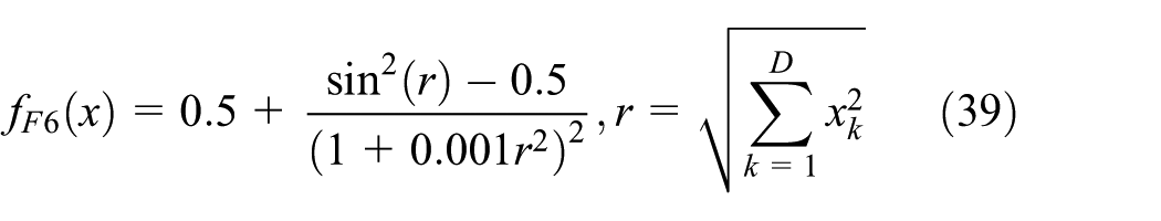
In the experiments, the search range of x k is set to (−10, 10), the swarm size is N = 50, the problem dimension is D = 5, and the learning factors take the standard values c1 = c2 = 2. The maximum and minimum inertia weights are set to wmax = 0.9 and wmin = 0.4, respectively. Under identical initial populations and random number sequences, PSO, APSO, and D-APSO are executed separately, and the variation of the global best fitness value with iteration number is recorded. The results are shown in Figure 8.
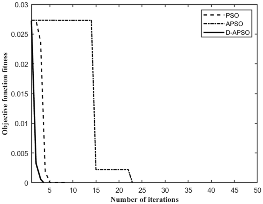
Test plot of the D-APSO algorithm.
As can be seen from Figure 8, D-APSO exhibits a faster convergence rate and a more stable convergence process compared with PSO and APSO.
Optimization results and comparative analysis
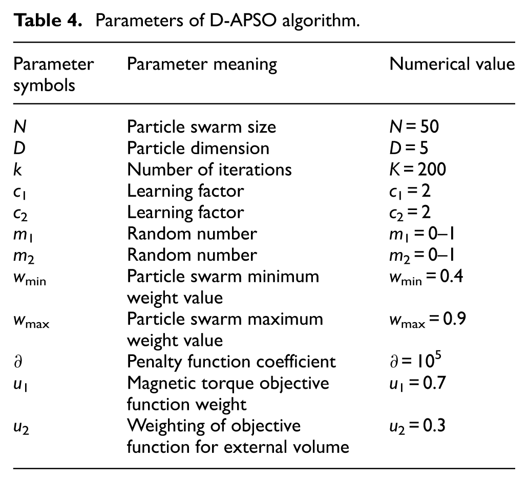
The original model to be optimized in this study is shown in Figure 2, and the parameters of the original design values are listed in Table 2. The D-APSO algorithm was implemented within the MATLAB environment, and the parameter settings used throughout the optimization process are detailed in Table 4.
Parameters of D-APSO algorithm.
Due to the stochastic nature of multi-objective particle swarm optimization algorithms, the results of a single run may be unstable. Therefore, multiple independent runs and averaging are required to reduce fluctuations caused by randomness and improve result reliability. In this paper, the average of five runs is taken as the final result, with all values rounded to two decimal places. The calculated results of the models obtained by PSO, APSO, and D-APSO are compared in Table 5, and the corresponding optimization performance is summarized in Table 6. The comparative convergence curves of the optimization algorithms are shown in Figure 9.
Comparison of the calculated results of PSO, APSO, and D-APSO.

Comparison of optimization performance among PSO, APSO, and D-APSO.


Comparison of the convergence curves of the optimization algorithms.
As can be seen from Table 6, under the same design variables and constraints, all three algorithms are able to reduce the volume V while increasing the output torque T, thereby improving the magnetic torque density. Among them, D-APSO achieves the best overall performance. Compared with the pre-optimization case, V decreases by 1.58%, T increases by about 4.82%, and the magnetic torque density ultimately improves by about 6.51%, which is significantly better than PSO and APSO. The fitness curves in Figure 9 further indicate that D-APSO decreases more rapidly and continues to improve in the later stages, reaching a lower objective function value, whereas APSO is more likely to level off prematurely at a higher value, and PSO converges more slowly with a poorer final optimum. In summary, D-APSO exhibits superior convergence speed and global search capability, with better stability and robustness, making it more suitable for the RMNMD parameter optimization problem.
The parameters optimized by D-APSO were imported into ANSYS Maxwell for 3D modeling and finite-element simulation, and the resulting magnetic torque was 16.412 N·m. The magnetic flux density distribution and the torque simulation interface of the optimized RMNMD are shown in Figure 10. The parameters before and after D-APSO optimization, together with the MATLAB analytical results and the FEA simulation results, are listed in Table 7. The comparison shows that the discrepancy between the finite-element results and the analytical predictions after optimization is within 1%, which further confirms the accuracy of the derived magnetic torque mathematical model and the feasibility of the D-APSO-based optimization approach.

The optimized RMNMD flux density distribution and FEM data.
Comparison of pre and post optimization results.

Conclusion
This paper addresses the requirements of high torque density and miniaturization for the radial meshing nutation magnetic drive system (RMNMD) by completing its analytical modeling, parameter optimization, and simulation verification. First, an analytical mathematical model for the RMNMD output magnetic torque was established, and key operating conditions at typical slip angles were validated through three-dimensional finite-element simulations in ANSYS Maxwell. Good agreement between the analytical predictions and simulation results demonstrates that the proposed model can serve as an effective evaluation basis for structural optimization.
To ensure that the performance improvement originates from structural parameter refinement rather than an increase in permanent-magnet usage, the total amount of permanent-magnet material was constrained to remain constant. With the dual objectives of maximizing the output magnetic torque and minimizing the overall volume, a fitness-feedback-based dynamic adaptive particle swarm optimization algorithm (D-APSO) was introduced to perform multi-variable, multi-constraint optimization. The results show that, compared with the initial design, the RMNMD output torque increases by 4.82%, the overall volume decreases by 1.58%, and the magnetic torque density improves by 6.51%. Moreover, D-APSO achieves better overall optimization performance and a faster convergence trend than PSO and APSO.
These results indicate that the integrated framework proposed in this study—analytical modeling, D-APSO-based optimization, and simulation verification—can effectively enhance the unit-volume output capability of the RMNMD under realistic engineering constraints, providing a reproducible analysis and optimization pathway for achieving high torque density and miniaturized design of nutation magnetic gears.
Footnotes
Handling Editor: Xiaodong Sun
Funding
The authors disclosed receipt of the following financial support for the research, authorship, and/or publication of this article: This work was supported by the 2024 Fujian Provincial Department of Education Research Project for Young and Middle-aged Teachers (Science and Technology Category) (Project No. JAT241306).
Declaration of conflicting interests
The authors declared no potential conflicts of interest with respect to the research, authorship, and/or publication of this article.