
Abstract
Electrifying non-road mobile machinery is vital for reducing emissions and improving energy efficiency. Replacing conventional hydraulic systems with electro-hydrostatic actuators is a key step in this transition. However, developing controllers that ensure dynamic performance, energy efficiency, and thermal management remain challenging. This paper proposes an optimal energy-saving controller, LQFFRO, for an EHA integrated into a wheel loader. The LQFFRO minimizes energy consumption and improves thermal performance while maintaining precise trajectory tracking under varying loads. Simulation results show that LQFFRO achieves tracking accuracy comparable to a PID controller, with position errors within 3 mm, while significantly reducing peak current and voltage. It also lowers the electric motor’s temperature by 2.5°C and reduces energy consumption by 0.395 kJ per cycle, leading to annual energy savings exceeding 2.84 million kJ compared to PID. Lyapunov-based analysis confirms the closed-loop system’s robustness under disturbances. These results confirm that LQFFRO controller effectively balances dynamic performance, energy efficiency, and thermal stability, contributing to the reliable and sustainable electrification of non-road mobile machinery.
Keywords
Introduction
Electrification of non-road mobile machinery (NRMM) offers significant advantages over conventional machines, including reduced emissions and improved energy efficiency.1–3 To facilitate this transition from traditional to hybrid or fully-electric NRMM, advancements are required not only in powertrain configurations, but also in the electrification of conventional hydraulic actuation systems.4–9 One promising approach is the adoption of electro-hydrostatic actuators (EHAs) to substitute the centralized pump-driven system, which have been shown to improve overall system efficiency.10–12 However, from the perspective of original equipment manufacturers, verification of this approach remains at the laboratory stage, 13 as successful implementation on NRMM requires comprehensive consideration of the EHA’s dynamic performance, energy consumption, thermal behavior, and other operational factors from the system level.14,15 To meet these requirements, designing the new controller that makes EHA integrated into NRMM rapidly is necessary.
Subsequent work introduced control strategies incorporating power regulators, though these designs often added components (normally proportional valves and accumulators) into EHA, increasing system weight and omitting real load conditions. 16 Precise estimation of load mass that EHA resisted assisted the designed controller to enhance robustness. 17 Shen et al. addressed the issues of instabilities caused by EHA’s nonlinear factors through using virtual decomposition control. 18 Two high precision controllers of EHA eliminate the effects brought from system uncertainties and make sure the asymptotic stability.19,20 Latest developments have applied AI-assisted techniques—such as Long Short-Term Memory networks—to enhance PID control on EHA. 21 Despite ongoing research efforts, most existing studies primarily focus on dynamic performance and do not validate their control strategies under real load conditions. Additionally, the controller’s energy use and its impact on electric motor (EM) temperature are often overlooked, though EM temperature strongly affects EHA performance and efficiency. Excessive heat can damage insulation and magnets, reducing motor efficiency and lifespan. 22
Dynamic performance still remains the primary objective, incorporating energy consumption into the cost function naturally transforms the problem into an optimal control framework. 23 Within this framework, methods such as linear quadratic regulator (LQR), model predictive control, and reinforcement learning are commonly employed to solve such optimization problems. 24 Although model predictive control and reinforcement learning can be executed in real time, their high computational complexity and reliance on high-fidelity models limit their practical deployment.25–29 For example, model predictive control frequently requires expensive computing hardware (e.g. an Intel Core i7-10700F CPU), making the resulting machine economically unviable for the market. 30 Furthermore, Reinforcement learning typically requires extensive offline training to achieve reliable performance. This process is not only time-consuming but also hinders its practical deployment in real-world systems. In contrast, LQR, as an offline optimal control method, offers a computationally efficient framework with guaranteed stability, making it widely used in engineering. The LQR controller combined with a Kalman filter and a full-order observer was implemented on the electric motor (EM) of an EHA. 31 While the cited work alludes to the potential for improved energy efficiency with LQR, it provides no empirical data to substantiate this claim, nor does it account for realistic load conditions. 32 In summary, a significant gap persists in the existing research: control strategies are designed and validated without incorporating actual operational loads and realistic sensor deployment. Consequently, these studies fail to simultaneously demonstrate superior dynamic response, reduced energy consumption and lower operating temperature, which are necessary for practical EHA implementation on NRMM.
Therefore, this research introduces a novel optimal control strategy, LQFFRO for an EHA integrated into a wheel loader. The highly dynamic and high-load duty cycles of a wheel loader, a key NRMM, impose strict requirements on actuator response, efficiency, and thermal management. Excessive heat generation is a critical issue, directly jeopardizing the electric motor and hydraulic system’s longevity. The proposed LQFFRO controller is novel in its holistic, system-level design that integrates established LQR and observer techniques into an offline feedforward–feedback framework, achieving simultaneous optimization of dynamic performance, energy efficiency, and motor temperature for EHAs in non-road mobile machinery using only a single position sensor. The LQFFRO integrates three components: an energy-optimizing LQR feedback controller for trajectory tracking, a feedforward compensator to reject internal and external disturbances, and a reduced-order observer for state estimation, enabling practical implementation with only a position sensor. The system’s stability and robustness are rigorously guaranteed through a Lyapunov-based analysis. Performance was evaluated via MATLAB, comparing the LQFFRO against conventional PID and a standard LQR-based Integral-Observer controller (LQIRO). The results demonstrate that the LQFFRO achieves superior trajectory tracking accuracy while simultaneously fulfilling its multi-objective design goals: it significantly reduces peak power events—which can degrade the EM’s lifespan—and improves overall energy efficiency. A critical outcome is the consequent reduction in EM heat generation, which directly enhances the thermal performance and operational reliability of the entire EHA system. These improvements in efficiency and thermal management directly translate to improved dynamic response, reduced wear, and increased longevity of the EHA. This control strategy can also be readily adapted to other types of NRMM employing EHAs for repetitive lifting functions, via straightforward parameter tuning, thereby advancing electrification of NRMM.
This paper is organized as follows: Section ‘Introduction’ introduces the research question, the aim of the paper and the contribution. Section ‘Modelling of EHA’ presents the discrete-time EHA model. Section ‘Problem formulation’ outlines the control design requirements. Section ‘Controller design’ details the design of the LQFFRO algorithm and its stability analysis. Section ‘Simulation results and discussion’ discusses simulation results in terms of dynamic and energy performance. Finally, section ‘Conclusion’ concludes the paper and outlines directions for future work.
Modeling of EHA
In this study, the EHA is integrated into a wheel loader to carry out boom lifting and lowering operations, with its system layout illustrated in Figure 1. The system is assumed to consist of an electric motor, an axial piston pump, a hydraulic manifold, a symmetric cylinder, the boom of the wheel loader, and a position sensor. The EM delivers power to drive the pump, which supplies hydraulic fluid to the cylinder, causing the piston rod to extend or retract and thereby adjusting the boom’s position. Prior to modeling the EHA system, three simplifying assumptions are made: (1) energy losses in the hydraulic manifold are negligible; (2) the friction force is constant; (3) the influence of position measurement error has not been considered.

EHA for lifting function.
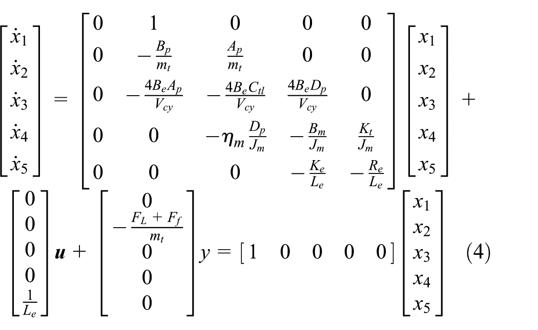
Numerous papers have already introduced EHA models, regardless of the system configuration—whether low-order or high-order models.33,34 Accordingly, the fifth-order dynamic model of the EHA system is directly provided as follows:

In order to build the state-space model, state vectors and a control vector are defined as:


Based on equations (2) and (3), reformulating equation (1) in continuous-time domain gives:
Since this study is conducted in discrete-time domain, zero-order hold method is adopted to transform equation (4) with a simpler format:

where
Problem formulation
Real-world disturbances are emphasized in Section ‘Introduction’, and a reliable reference trajectory—sourced from either real-world measurements or digital twin models—is also essential. Based on these considerations, the simulation conditions and control requirements are established. All geometric and dynamic parameters are scaled down to simplify the model. Table 1 lists the detailed scaled parameter values of the major components in the EHA.
Scaled parameter values of major components.

Figure 2(a) depicts the trajectory of a hybrid wheel loader during a loading and unloading cycle, simulated within the Mevea™ digital twin environment. 35 The cycle begins with the unladen loader reversing from point A to point B. As it approaches point C, the bucket lowers in preparation for loading. At point C, the loader collects rocks by lifting the boom and tilting the bucket. It then reverses to point D, moves forward to point E to unload the material, and finally returns to point A to complete the cycle.

Simulation conditions: (a) trajectory of the wheel loader and (b) references for the EHA corresponding to the trajectory.
The piston motion following the reference trajectory is shown in Figure 2(b) over a 60 s cycle, with a fundamental sampling time of 0.001 s. The corresponding load force acting on the actuator, represented by
Based on the above information, the following requirements are defined for the controller design:
Ability to track the fixed trajectory depicted in Figure 2(b), despite the external load and internal friction.
Tracking error remains within the range of −3% to 3%. 36
The trajectory should be completed within a maximum duration of 60 s, placing the control task in the finite-time domain. 37
The EHA system includes only one position sensor; however, the engineer must monitor four additional state variables as defined in equation (2).
The EM current must not exceed the maximum allowable value specified in the product datasheet. In this study, the maximum current is set to 24 A.
To meet simulation conditions and requirements—particularly the finite-time trajectory tracking under disturbance with limited sensing and actuator constraints—the following controller design is proposed.
Controller design
The framework of the proposed LQFFRO controller is illustrated in Figure 3. For convenience in controller design, the overall system is divided into two channels: a feedforward channel and a feedback channel. Section ‘LQR for trajectory tracking problem with measured disturbance’ outlines the controller design process, while Section ‘Stability analysis’ introduces the stability analysis of the complete closed-loop system using Lyapunov stability theory.
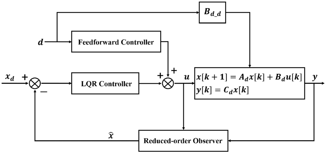
Block diagram of proposed LQFFRO controller.
LQR for trajectory tracking problem with measured disturbance
Given the fixed trajectory, the direct error feedback method is utilized:

where
It is straightforward to express the equation of the error at the next step:

Combining equations (6) and (7) and substituting into the state equation in equation (5) gives:

The desired trajectory can be expressed as:

where
The state equation for direct error feedback method integrated in LQR is built on the basis of equation (9) as follows:

The cost function is defined as:
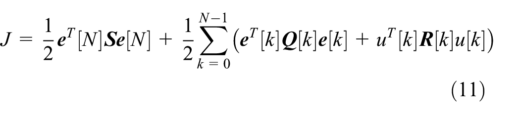
where

With the constraint that only single position sensor is attached to the EHA, a reduced-order state observer should be included.
Based on

where
Stability analysis
Estimated state variables replace all real state variables, which leads to one of reformulated equations as follows:

Taking equation (13) into equation (14) and reformulating gives:

where

T1: Designing

T2: Equation (15) also represents the error between actual value and estimated value in Appendix B.
T3: The desired trajectory depicted in Figure 2(b) can be characterized as a piecewise signal composed of several step signals. Consequently,
T4:
According to
Rewriting equation (15) gives:

Lyapunov function is chosen to be:

where

Substituting equation (18) into equation (20) produces:
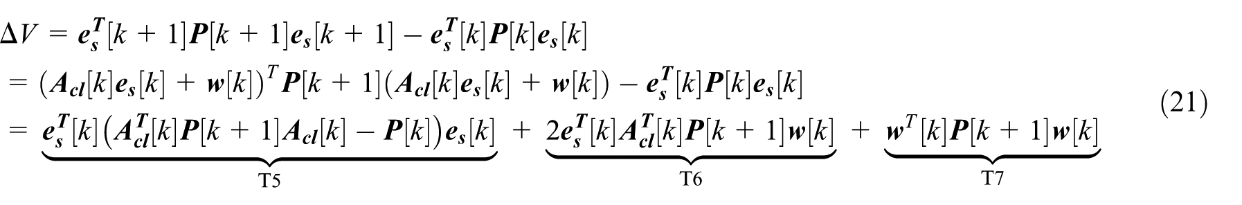
T5: Based on equation (50), one inequality can be expressed as:

Thus

where
T6: Bounding T6 by using Young’s inequality for matrices case gives:

Introducing equation (22) into equation (24) and reformulating leads to:
where
T7: It is natural to obtain the inequality:

Combining equations (23), (25), and (26) and rearranging equation (21) gets:

Such a

Expressing equation (28) back in terms of

Let
Hence equation (29) with

where
Iterating the above inequality produces:
Therefore

This is exactly the uniform ultimate boundedness statement:
Simulation results and discussion
To evaluate the performance of the proposed control strategy in Figure 3, simulations were conducted in MATLAB using two additional control strategies for comparison. The first controller is a classical three-loop PID strategy, commonly used in EHA systems, as illustrated in Figure 4(a). A proportional controller, namely P controller, is applied in the position loop, while proportional-integral (PI) controllers are used in both the speed and current loops. Notably, this control structure does not incorporate any observer. The second is the LQIRO controller, depicted in Figure 4(b), which integrates a LQR, an observer, and an integral controller—commonly used in industrial applications to compensate for external disturbances. These two controllers are compared with the proposed LQFFRO in terms of dynamic performance (Section ‘Dynamic performance’) and energy consumption (Section ‘Energy consumption’). Additionally, Section ‘Energy consumption’ includes further analysis of the electric motor’s temperature variations under each control strategy.

Block diagram of the other two controllers: (a) PID and (b) LQIRO.
Dynamic performance
The trajectory tracking performance of the three controllers—LQFFRO, PID, and LQIRO—relative to the reference trajectory is presented in Figure 5, with quantitative metrics summarized in Table 2. Overall, the proposed LQFFRO controller achieves trajectory tracking accuracy comparable to that of the conventional PID controller, while exhibiting superior robustness under varying load conditions. In contrast, the tracking performance of the LQIRO controller deteriorates markedly when exposed to realistic load variations.

Comparison of trajectory tracking under three controllers.
Comparison for trajectory tracking.

During the initial stage (0–15 s), the actuator is subjected to a fixed load corresponding to the stationary phase at 70 mm, as shown in Figure 2(b). Both LQFFRO and PID maintain the piston position with negligible error, whereas LQIRO fails to counteract the load instantaneously, producing an initial displacement deviation that is gradually compensated once its integral term becomes active. Between 15 and 18.5 s, the load force first decreases and then rises sharply, reaching its peak at 18.5 s. Under these conditions, neither LQFFRO nor PID achieves steady-state within the interval; however, their terminal errors remain within the acceptable range. In contrast, LQIRO is severely affected by the disturbance, resulting in a significant 16.13 mm deviation from the reference. During the subsequent interval (18.5–23.5 s), PID attains steady-state faster than LQFFRO but at the expense of a larger steady-state error, while LQIRO fails to settle. When tracking the 100 mm command, LQIRO exhibits an overshoot of approximately 4.6%, which is undesirable for precision actuation and potentially detrimental to operational safety. In this phase, PID achieves the fastest transient response, followed by LQFFRO. From 49.0 to 53.0 s, LQFFRO demonstrates a response speed comparable to PID but with slightly lower positional accuracy. In the final stage (53–60 s), both LQFFRO and PID accurately follow the reference trajectory, whereas LQIRO again fails to reach steady-state within the simulation period.
These results collectively confirm that the proposed LQFFRO controller provides satisfactory trajectory tracking comparable to PID, while exhibiting markedly improved disturbance rejection and robustness compared with LQIRO. Throughout the entire operating cycle, LQFFRO maintains position errors within 3 mm, fulfilling the prescribed tracking accuracy requirement.
Given that the dynamic performance of the EHA is primarily governed by the EM power characteristics, an analysis of its current and voltage responses provides valuable insight into system behavior. Under the fixed load conditions, the current profiles of the three controllers exhibit generally similar trends, as shown in Figure 6(a). However, the PID controller produces more frequent and higher current peaks, occasionally exceeding the 24 A limit specified in Requirement No.5 (Section ‘Problem formulation’), thereby violating the design constraint. In contrast, the proposed LQFFRO controller maintains smoother current variations and effectively suppresses transient spikes, while LQIRO displays even greater oscillations, confirming its reduced stability under varying loads.

Comparison of the EM (a) current and (b) voltage.
The corresponding voltage response in Figure 6(b) further illustrates these distinctions. The PID controller exhibits the most rapid and pronounced voltage fluctuations, particularly between 15 and 17.5 s, which correspond to its faster piston motion observed in Figure 5. When the external load increases sharply from 17.5 to 18.5 s, both LQFFRO and PID apply positive voltages to stabilize the piston, whereas LQIRO momentarily drops below 0 V, resulting in a marked loss of piston position. After 18.5 s, the voltage under LQIRO control remains higher as it attempts to recover from lagging tracking performance, while PID continues to exhibit higher voltage peaks than LQFFRO. During the unloading stage (48–52 s), a slight 2 V overshoot appears in the PID voltage response, leading to minor piston overextension, as also reflected in Figure 5.
Figure 7 shows that the reduced-order observers accurately estimate the actual motor current. According to Requirement No. 4, four state variables defined in equation (3) must be estimated. As the observers perform similarly well for the remaining three variables, only the current estimation results are presented for brevity. The extreme current values produced by LQFFRO are 23.11 and −7.40 A, while those of LQIRO reach 24.11 and −8.15 A. Apart from these peaks, both controllers exhibit comparable current profiles. Notably, LQFFRO remains within the specified 24 A limit in Requirement No.5, whereas LQIRO exceeds it.

Effects of reduced-order observers: (a) LQFFRO and (b) LQIRO.
Overall, the LQFFRO controller delivers stable and accurate trajectory tracking under varying loads, matching PID in steady-state precision while offering superior disturbance rejection. Although PID responds faster, it exhibits greater overshoot in voltage and current, whereas LQIRO fails to maintain stability. Thus, LQFFRO achieves the best balance between tracking accuracy and robustness.
Energy consumption
In addition to dynamic performance, EHA’s energy efficiency and thermal behavior under the three control strategies are evaluated in this section. The interior and shell temperatures of the electric motor, as well as the total electrical energy consumption during one operation cycle, are presented in Figures 8 and 9 summarized in Table 3.
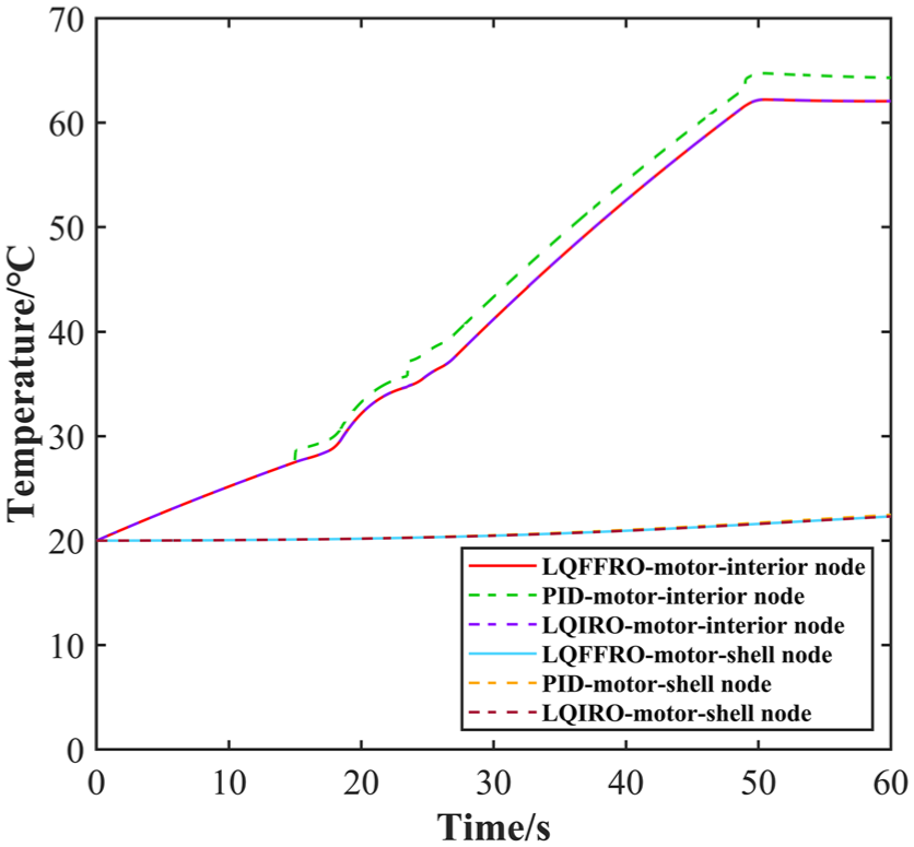
EM temperature changes under three controllers.

Energy consumption from the EM.
Final temperatures of the EM at 60 s.

The temperature variations of the motor nodes shown in Figure 8 closely follow the energy-consumption trends in Figure 9 confirming that heat generation in the motor is primarily governed by electrical losses. 38 Among the three controllers, the proposed LQFFRO controller demonstrates the most favorable thermal performance. At the end of the 60 s simulation, the motor’s interior temperature under LQFFRO control is 62.06°C, approximately 2.5°C lower than that of the PID controller (64.30°C as shown in Table 3), while the shell temperatures of both remain nearly identical. A lower interior temperature mitigates copper and iron losses, reduces insulation degradation, and thereby extends motor lifetime. In contrast, LQIRO maintains a similar temperature to LQFFRO at the interior node but achieves this through slower and less stable dynamic response, which is undesirable for practical applications.
Figure 9 illustrates the cumulative energy consumption of the EHA system during the entire trajectory. In the initial 15 s, the energy usage of all three controllers remains nearly identical, as the actuator remains stationary. Differences become evident after 15 s when the piston begins active motion under varying loads. Over the complete 60 s duty cycle, the total electrical energy consumed by the electric motor is 8.273 kJ for LQFFRO, 8.274 kJ for LQIRO, and 8.668 kJ for PID. Thus, the proposed controller achieves a 4.6% reduction in energy consumption compared with PID. Although the per-cycle saving appears modest, it becomes significant over extended operation. Assuming continuous daily use of 8 h, the LQFFRO controller would save approximately 11,376 kJ per day compared with PID, corresponding to 2.84 million kJ annually for a 250-day work year, equivalent to the electricity consumption of an average household for approximately 26 days. Such improvement translates directly to reduced electricity demand, extended battery endurance in electrified machinery, and lower operational costs.
Overall, these results demonstrate that the proposed LQFFRO controller not only preserves dynamic performance comparable to PID but also reduces peak current and voltage fluctuations, thereby lowering motor heating and improving energy efficiency. Such improvements enhance system durability, extend component lifespan, and contribute to the sustainable electrification of non-road mobile machinery.
Conclusion
This paper presents a novel LQFFRO controller for the EHA integrated into an electrified wheel loader performing repetitive tasks. The proposed controller effectively balances dynamic performance with improved energy efficiency and reduced EM temperature compared with conventional PID and LQIRO controllers, making it a practical and effective solution for the electrification of NRMM. Key findings are summarized as follows:
Simulation results demonstrate that the LQFFRO controller achieves trajectory tracking accuracy comparable to that of the conventional PID controller, maintaining position errors within 3 mm, while exhibiting superior robustness under varying load conditions. Compared with LQIRO, LQFFRO effectively suppresses current and voltage peaks, remaining within the 24 A current constraint and ensuring stable system operation. The Lyapunov-based analysis further verifies that the closed-loop system under LQFFRO control is uniformly ultimately bounded, confirming its robustness against model uncertainties and external disturbances.
From an energy perspective, LQFFRO reduces total energy consumption by 4.6% relative to PID and lowers the EM’s interior temperature by approximately 2.5°C, translating to substantial annual energy savings and extended motor lifespan.
Future work will focus on experimental validation using a physical test rig. The experimental study will involve testing the controller with simple reference signals, identifying variations in the state-transition matrix parameters, and refining the feedforward component to further enhance system robustness.
Footnotes
Appendix A
Consider a discrete-time linear system:
The objective is to minimize the quadratic cost function:
where
Starting from the terminal time
When
To keep all indices consistent,
Optimal control law is derived from equation (37) as the following:
where the feedback matrix gain
Introducing equation (38) to equation (36) gives the minimized cost as follows:
where the cost matrix, namely, the solution of Discrete-time Algebraic Riccati Equation (DARE) is:
When
Therefore, the equation (42) can be reformulated as:
According to equation (33),
where the feedback matrix gain
Similarly, introducing the optimal control law to equation (43) could generate the minimized cost as follows:
Equations (44)–(46) have the identical form with equations (38)–(40) respectively, hence employing inductive reasoning to bring the general optimal control law of LQR in discrete-time domain leads to:
where
The function of general optimal cost is:
where
Note: When
Appendix B
Design a reduced-order observer for the following system with a disturbance term:
where the output of the system is solely a function of the observable state
To transform the initial system into observable canonical form (OCF), transformation matrix
where
where
The observer for unobservable parameters can be defined as:
According to the output equation in equation (53), the estimation of
Substituting equations (53) and (55) into equation (54) and rearranging the equation gives:
The estimation error for the unobservable state is defined as:
To verify that the estimation error
From equation (58), it is evident that estimation error
Acknowledgements
Thanks for the financial support from International Joint Doctoral Education Fund of Beihang University. Also, thanks for the help from Prof. Tatiana Minav working in Tampere University, Finland. Prof. Tatiana Minav is willing to offer valuable comments to help me improve this paper and agreed with submitting this paper to the journal.
Handling Editor: Jesus Felez
Ethical considerations
This article does not contain any studies with human or animal participants.
Funding
The authors disclosed receipt of the following financial support for the research, authorship, and/or publication of this article: This work was supported by the Open Fund of Innovation Center for Control Actuators and International Joint Doctoral Education Fund of Beihang University, which are the two fundings’ names.
Declaration of conflicting interests
The authors declared no potential conflicts of interest with respect to the research, authorship, and/or publication of this article.