
Abstract
Modern industrial tote dumpers and lifters are equipped with long-stroke single-rod hydraulic cylinders. For years, valve-controlled cylinders have been used in tote dumpers. Valve-controlled actuators are highly inefficient due to huge power losses in throttling valves. They also need a cooling system to remove the wasted heat energy from the hydraulic oil. This article introduces a low-cost throttle-less hydraulic circuit to control the single-rod cylinder of a tote dumper. The system consists of a motor-driven gear pump, an On/Off solenoid valve, to redirect the differential flow of the single-rod hydraulic cylinder and a counterbalance valve, which makes the circuit controllable for assisting loads and keeps the load in position with no effort from the hydraulic pump. Experimental results demonstrate the performance of the circuit. A test rig has been designed to simulate a lifting load. The energy efficiency of the circuit is determined by comparing a valve-controlled circuit with the proposed circuit. The proposed circuit composition is not only efficient and simple but is also accurate in terms of position response using a proportional controller. The circuit is easy to control since the only needed measurement is the displacement of the actuator. The circuit, however, does not recycle energy.
Keywords
Introduction
Single-rod hydraulic cylinders are commonly used in different fields of industry, from airplanes to construction machines, mining machines, and industrial lifters. The efficiency of operation of such industrial machines is a crucial parameter not only because of the cost of the energy but also for the environmental impact of operation. For example, a typical excavator machine is energized by a 147-hp (110 kW) diesel engine and consumes 33 L of diesel fuel per hour, and only 30% of this energy is used for digging and lifting loads.1,2 The rest of consumed energy is wasted in mechanical and hydraulic elements. About 35% of the delivered energy to the hydraulic system is consumed in metering valves that only heats up the hydraulic oil.1,2 A centralized hydraulic power unit delivers the pressurized hydraulic fluid to the ports of metering valves, and each valve controls one cylinder. Centralized hydraulic systems are not only bulky, heavy, and noisy,1,3,4 but they also increase the weight and cost of the machine. Moreover, the oil cooler of the machine consumes energy to dissipate the excessive heat produced by metering valves. Furthermore, the amount of pollutants emitted by the machine in the form of carbon monoxide, nitrogen dioxide, and nitrogen monoxide is considerable. 1 Any improvement in energy efficiency of hydraulic systems reduces the environmental impact of industrial activities and saves energy.
One solution to improve the efficiency of industrial machines is to design a system in which no metering element is employed. These systems are recognized either as pump-controlled hydraulic or electro-hydrostatic systems. When a hydraulic cylinder is controlled with a variable displacement pump and the prime mover is a fixed revolutions per minute (RPM) motor, the circuit is variable displacement pump controlled. And when the pump is fixed displacement and the prime mover is a variable RPM electric motor, the cylinder is named variable speed pump-controlled or electro-hydrostatic actuator (EHA).5,6 Pump-controlled hydraulic actuators are also known as throttle-less hydraulic actuators. 7 These systems do not need a central hydraulic power unit and each cylinder is controlled by a pump. Indeed, when energy is required, the pump supplies the fluid to the cylinder directly. Two types of hydraulic cylinders (actuators) are used in industry: double rod or symmetric and single rod or asymmetric. Double-rod hydraulic cylinders are larger than single-rod ones. They need more space for installation and operation as compared to single-rod cylinders. Throttle-less hydraulic circuits for double-rod hydraulic cylinders have been well developed and used in industry. 8 The challenge of implementing a throttle-less single-rod hydraulic cylinder is to deal with different flows at two sides of the cylinder by using pump and maintain the performance of the operation. 1 To this point, two methods have been used for pump control of single-rod hydraulic cylinders: using asymmetric axial piston pumps and conventional pumps. 9 As compared to conventional pumps, asymmetric axial piston pumps are new, expensive, and requires high maintenance.9,10 Two major methods have been employed to control flows of a single-rod hydraulic cylinder by using conventional pumps: using two pumps and one pump. When two-pump systems are used, each pump controls the flow of one side of the single-rod cylinder. Using two pumps for controlling each cylinder of an industrial machine makes the machine expensive and heavy. 9 Moreover, synchronizing displacements of two pumps and keeping their flows at the same flow rate of the cylinder in real time are challenging. 11
Many throttle-less hydraulic circuits to control a single-rod hydraulic cylinder have been designed and tested.2,7,12–16 However, none of these designs have been widely used in the market indicating that there is still no ideal solution for throttle-less single-rod hydraulic cylinders. The common challenge of these circuits using one pump is to connect one chamber of the cylinder directly to the low-pressure side of the hydraulic circuit. Researchers have used different methods to overcome existing concerns.1,7,17,18 Nevertheless, existing solutions are either expensive or pose some limitations. 17 Simplicity, reliability, efficiency, and low cost are important factors of an ideal industrial hydraulic circuit. In this article, design and experimental validations of a simple, controllable, energy-efficient, lightweight, reliable, low-noise, and low-cost throttle-less hydraulic circuit is presented. The proposed circuit is formed by a variable RPM electromotor coupled to a fixed displacement gear pump, a counterbalance valve, and an On/Off solenoid valve. Experimental validations are conducted to show how accurately a single-rod hydraulic cylinder moves using this circuit. Moreover, a comparison between the proposed circuit and the circuit without the counterbalance valve shows that achieving a comparable performance for a circuit without counterbalance valve using industrial off-the-shelf variable-frequency drive (VFD) and an induction motor, without any break as a prime mover, and applying just a simple proportional controller is challenging. The authors introduced a simple, controllable, energy-efficient, lightweight, reliable, low-noise, and low-cost system for industrial applications.
Experiments are performed on a test rig that emulates a tote dumper or a lifter. Off-the-shelf industrial components are used to set up the test rig. This article presents the details of the proposed circuit and demonstrates the efficiency and performance of the circuit.
The rest of the article is organized as follows. Section “A review on existing circuits” presents a review on throttle-less hydraulic circuits for single-rod cylinders. The details of the proposed circuit are explained in section “The proposed circuit.” Section “Test rig and experimental results” presents the experimental evaluation of the proposed circuit. Also, the response accuracy of the proposed circuit in closed-loop position control is outlined in this section. Section “Energy efficiency considerations” reports the energy efficiency considerations of the proposed throttle-less circuit and compares it with a conventional valve-controlled circuit. Conclusion is outlined in section “Conclusion.”
A review on existing circuits
Lodewyks 19 applied the concept of the hydraulic transformer to compensate differential flow rates of a single-rod cylinder (Figure 1). As illustrated in Figure 1, the hydraulic transformer ratio (flow ratio) needs to match the ratio of the hydraulic cylinder. 20 Nowadays, hydraulic transformers are available in certain ratios,21,22 while hydraulic cylinders are available in a wide variety of ratios. Pumps shown in Figure 1 operate in four hydraulic quadrants. Figure 2 defines the four operation quadrants of a hydraulic machine (pump/motor). As observed in Figure 2, when PA > PB and oil flows from port “B” to port “A,” the hydraulic machine receives energy from the prime mover and feeds it to the hydraulic circuit; it works in the first quadrant and in pumping mode. When PA < PB and oil still flows from port “B” to port “A” of the hydraulic machine, it works in second quadrant in motoring mode, receives energy from the hydraulic circuit, and feeds it to the prime mover.

Hydraulic transformer compensates the differential flow rates of a single-rod cylinder.

Four operational quadrants of a hydraulic machine.
Cleasby and Plummer 23 designed a hydraulic flight simulator using a special ratio hydraulic cylinder (see Figure 3). They used a variable speed (RPM) electric motor coupled to a tandem pump unit formed by two identical fixed displacement pumps to control each hydraulic cylinder with the ratio of 1:2 as a limb of a Stewart platform.

Two pumps control a 1:2 ratio single-rod cylinder.
The tandem pump assembly shown in Figure 3 operates in four quadrants and can recycle some potential energy in motoring mode. This circuit was designed for cylinders with particular cylinder ratio. The presence of a wide variety of cylinder ratios available in industry limits the use of this design.
There are some different configurations of using two pumps to control a general single-rod cylinder. 11 Two techniques of using two pumps to control a general single-rod cylinder are as follows: (1) using two variable displacement piston pumps coupled to a fixed RPM prime mover (diesel engine) and (2) using two fixed displacement pumps coupled to two variable RPM motors. Lin et al. 24 applied a concept of a two-pump circuit to the boom cylinder (a general ratio cylinder) of an excavator. They coupled one variable displacement pump to the prime mover (electric motor coupled to an internal combustion engine) and a hydraulic motor to an electric generator to recycle some potential energy when the boom was lowered; they showed that the positioning was not accurate and the speed of the boom was not stable. 24 In general, using two pumps to control a single general asymmetric cylinder makes the machine complex and expensive. Also, it makes the machine requiring high maintenance and heavy.
Hewett 12 patented the idea of using one pump for a hydraulic cylinder. He used a three-way two-position valve to redirect the differential flow rates of a single-rod cylinder (see Figure 4). The hydraulic pump in this circuit operates in four hydraulic quadrants. The circuit was applied to some forestry machines.17,25 However, since one side of the cylinder is always connected to the low-pressure side of the hydraulic circuit, it makes the circuit unstable in the case of load switching, for example, from assistive to resistive. 17

A circuit using a three-way two-position valve to redirect the differential flow of a single-rod cylinder.
Ivantysynova 3 applied the closed-loop pump technology to piston pumps of a construction machine. This technology reduced weight and improved the efficiency of the mobile machine. R Rahmfeld 26 implemented two pilot check valves to redirect the differential flow of a single-rod cylinder (see Figure 5). The pump operates in four quadrants and can feed some energy to other pumps which are connected to the same prime mover (they are not shown in Figure 5). Zimmerman et al. 2 and Grabbel and Ivantysynova 13 applied the circuit to a concrete pump truck, a loader, and a multi-joint manipulator. Later on, Williamson and Ivantysynova 18 showed that in some load conditions, two pilot check valves and swash plate of the piston pump are unstable. They overcame some issues, but the hydraulic circuit is not widely used in industry. 17
Throttle-less single-rod cylinder with pilot check valves.
Wang et al. 17 theoretically showed that the circuit illustrated in Figure 5 operates unstably under some load conditions. They replaced the two pilot check valves with a shuttle valve and two On/Off solenoid valves for bleeding and adjusting pressures in extreme load conditions (see Figure 6). To stabilize swash plate and load motion, an internal control loop was implemented. The control loop required real-time pressure and the position monitoring to stabilize the circuit. 17

Hydraulic circuit for single-rod cylinders using a shuttle valve.
There have been efforts to apply some versions of already reviewed circuits to industrial lift trucks. For example, Huayong et al. have applied a version of circuit in Figure 5 to an elevator application. They used a special servomotor as the prime mover and special single-rod cylinder. 27 The price and type of cylinder limit the application of the circuit. Minav et al. used a simple throttle-less circuit by using a servomotor as a prime mover for an electric forklift. They have not reported about the accuracy and performance of their circuit. 28 Minav et al. used a modified throttle-less circuit shown in Figure 4 to a forklift. They have recycled some energy when the load was free falling, but they reported the load positioning was not accurate and speed of the load was vibrating. 29
The proposed circuit
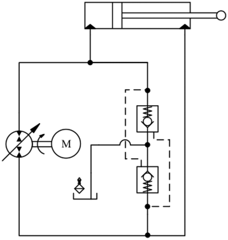
Figure 7 shows the schematic of the proposed circuit. The actuator VIII is a single-rod hydraulic cylinder. The differential flow rate exchange from two sides of the cylinder is controlled by an On/Off valve IV and two check valves IIIa and IIIb. The open circuit section of valve IV is replaced by a check valve to protect pump I against cavitation in extreme load conditions. The counterbalance valve VI incorporates a check valve VIb for the free flow in one direction and an adjustable relief valve VIa to control the flow in reverse direction.

Schematic of the proposed throttle-less hydraulic circuit.
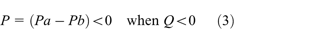
Figure 8 shows a closer view of the counterbalance valve VI. Counterbalance valves usually act as safety valves and are common for systems working with overriding (running-away) or suspended loads. They are used to protect loads against free falling. In the circuit shown in Figure 7, the counterbalance valve VI blocks the direct connection of the port B of the cylinder to the tank. Also, when the operator wants to keep the load at its position, the counterbalance valve blocks the return line from the cylinder with no effort from the prime mover. The force balance equation of a counterbalance valve is described as 30

where

(a) A counterbalance valve schematic and (b) symbol of a counterbalance valve.
When

Pump I operates in pumping mode. The counterbalance valve does not allow the circuit to work in motoring mode; therefore, it cannot recycle energy.
Two pressure relief valves Va and Vb in Figure 7 protect the hydraulic circuit against over-pressure. They are closed in normal conditions. In Figure 7, at rest condition, the prime mover is off and load is stopped at some position. Both the internal check valve of solenoid valve IV and the check valve IIIa keep PA and Pa almost at tank pressure. The counterbalance valve VI remains off and blocks the hydraulic line. The check valve IIIb keeps the pressure at port b of pump I almost at the tank pressure. Afterward, load M builds up pressure at port B of cylinder VIII and stands at its position with no effort from prime mover. When motion is needed, pump I will start from unloading condition.
To perform the lowering motion, pump I feeds the hydraulic fluid to port A of the cylinder (Figure 7) and pressure builds up at port A of the cylinder. The check valve IIIb opens the tank to port b of the pump. The pressure at port b will be almost at tank pressure. Once the pilot pressure of the counterbalance valve reaches the cracking pressure, the line from port B of cylinder is opened to port b of the pump. In this case, the On/Off solenoid valve IV will stay off and the pump provides the hydraulic oil to port A of the cylinder directly. The tank provides the pump with the differential flow rate of two sides of single-rod cylinder VIII. The pump works in pumping mode (first quadrant in Figure 1)
To raise the load, the pump supplies the hydraulic fluid from port b to the hydraulic circuit (Figure 7). Port a of the pump acts as suction port, and valve IV is switched on. Valve IV opens port a of the pump and port A of the cylinder to the tank. The extra fluid from port A is diverted to the tank through valve IV. The hydraulic fluid from the pump port b passes through the check valve VIb and builds up pressure at port B of the cylinder. The check valve IIIb will stay closed under pressure. In this case
And pump I works in pumping mode (third quadrant in Figure 2). The circuit does not recycle energy. The prime mover II is a variable RPM electric motor. PA, Pa, PB, and Pb are readings of pressure transducers, T is a tachometer, LS is a linear position sensor (transducer), and data acquisition (DAQ) board is an input/output (IO) board.
Test rig and experimental results
Figure 9 shows the test rig was developed to validate the proposed circuit. The prime mover was an induction motor which was controlled by a VFD. VFDs are common RPM controllers in market. They are widely used in industry. Pressure transducers and linear position transducer were used in test rig to sense the circuit parameters and record them to the computer through an eight-channel Quanser DAQ.

Test rig (a) circuit, (b) submerged components, and (c) load setup.
Pump, check valves, and pressure relief valves were submerged in the hydraulic fluid to reduce the span of hydraulic lines. The cracking pressure of check valves was set to

Control structure of the test rig.
Test rig parameters.
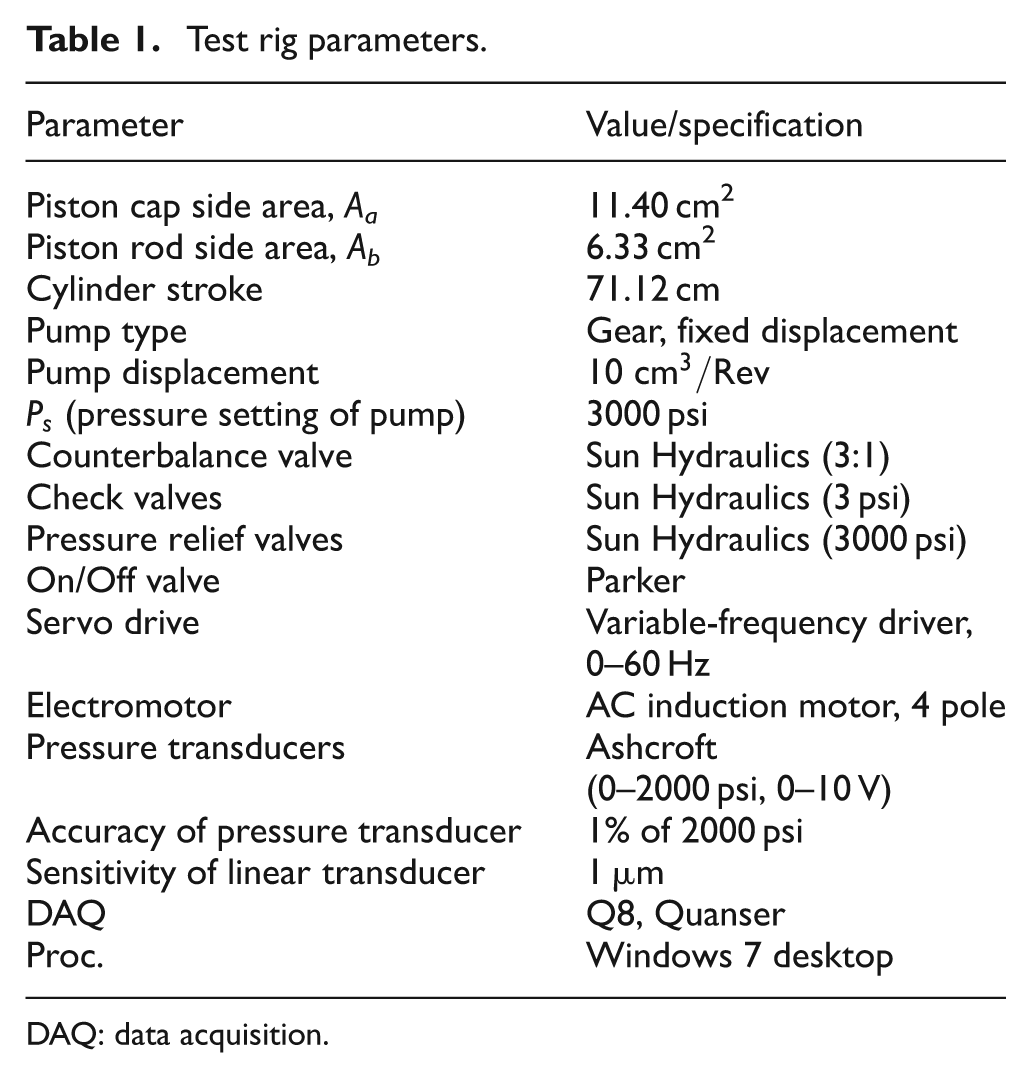
DAQ: data acquisition.
Altogether, four sets of tests were performed on the test rig to validate the proposed circuit. The control loop was closed on readings of the actuator position transducer and a simple proportional control was applied for all tests. The first test was designed to prove the consistency and accuracy of the position response. The second test was designed to study the effect of changing load to system response. In the third test, the effect of motion pattern variation on the response of the system was studied. The last test was performed to investigate the circuit power consumption and compare the efficiency of the proposed circuit to a valve-controlled circuit.
In the first test, a periodic square position signal was applied to the circuit for a time period of 300 s (Figure 7), the control loop was closed on readings of cylinder position transducer, and the load was 300 lb. The response of the circuit was repetitive and consistent. Figure 11(a) shows two periods of the desired and actual position response of the system between 144 and 224 s. The delay, rise, and settling times of the system response in both the up- and downstrokes are shown in Figure 11(a) too. The delay response time was about 0.5 s. It was attributed to the response delay of VFD, inertia of the rotating parts of the pump-motor unit, and compressibility of the oil.
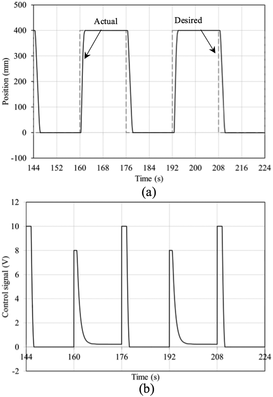
First test: (a) desired and actual positions and (b) voltage control signal to VFD.
In upstroke as shown in Figure 11(a) between 160 and 176 s and 192 and 208 s, the controller read some steady-state error. Figure 11(b) shows a small amount of voltage control signal for the same period of time (e.g. 194–208 s). During this period of time, the pump rotated in low RPM and built some pressure that was not enough to overcome the weight of the load. Also, as it is illustrated in Figure 11(b), the control signal has been saturated to 10 V by IO board in downstroke (pressurize cap side of cylinder) and 8 V in upstroke by authors (pressurize rod side of cylinder) to prevent uncontrollable position overshoot. Figure 12(a) shows the upward and downward velocity of the load, and Figure 12(b) demonstrates the pressures at the cylinder ports for two periods of motion.

First test: (a) load velocity and (b) pressures at the cylinder ports.
Figure 13 shows a close-up view of the position error and control signal of the circuit for the time period of 194–198 s. It shows that the steady-state error of the response was ±0.034 mm when the desired displacement was 400 mm (±0.00085% of stroke). The control signal induced by relevant steady-state error was about 0.25 V. During this time, the low inducted RPM rotation of pump just fed its internal leaks and created some pressure pulsations. In down (rest) position (e.g. 150–160 s), the steady-state error was not big enough to create some significant voltage control signal. As Figure 12(a) illustrates for the same time period of 144–224 s, the upward and downward speeds of the load reached about 475 and 265 mm/s, respectively. The speed ratio, in this typical result, was equal to the cylinder ratio. Figure 12(b) shows the pressure readings from two ports of the cylinder for the same time period of 144–224 s.

First test, a close-up view of the error and control signal of Figure 11(b).
In Figure 12(b), the period starts with downward stroke. For lowering the load, the pump was needed to build up pressure at the pilot port of the counterbalance valve to open the line between port b of the pump and port B of the cylinder shown in Figure 7. When the pressure at the pilot port of the counterbalance valve reached 310 psi, the counterbalance valve opened the circuit. And as long as the pump fed port A of the cylinder and pressurized the pilot port of the counterbalance valve, the counterbalance valve remained open. In Figure 12(b), the first peak of pressure PB shows that more pressure was generated in chamber B than in chamber A, which was attributed to the piston area difference and the load-induced pressure. The second peak of pressure, at time 148 s, presents the effect of the load dynamics and compressibility of the hydraulic fluid when the cylinder stopped. To raise the load, the pump fed fluid to port B of the cylinder through the check valve of the counterbalance valve (Figure 7). Pressure PB was built up to the value required to overcome the load dynamics and friction forces, and performed the upward motion. When the load reached the maximum position, the pump stopped at t = 162.5 s, and the check valve of the counterbalance valve closed. Small low-pressure ripple shows the effect of load dynamics and the fluid compressibility. At the rest (up) position (e.g. 163–176 s), the pressure at port A was the tank pressure and the pressure at port B was stabilized at the backpressure of the load against the counterbalance valve. Comparing Figures 11(b) and 12(b) shows that in rest when the control signal was lower than the threshold value (about 0.2 V), the pump did not rotate and there was no pressure ripples at cylinder ports (163–176 s). When the control signal was higher than the threshold value, the pump rotated in a very low RPM and created pressure pulsations (193–208 s). The test showed that the circuit was controllable, the response was repetitive and consistent, and the accuracy of the position response was about ±0.034 mm.
In the second test, to examine the effect of load changes to the response of the hydraulic circuit, three different loads were applied to the circuit in Figure 7. The position responses of the circuit under the same gain of the proportional controller were recorded when the desired position was a square signal. Figure 14(a) shows the desired and actual positions of the circuit for loads 20, 150, and 300 lb. Experiment results proved that the position response of the circuit was not sensitive to the load size. Figure 14(b) shows the error response of the circuit for those three different loads. The test showed that the response of the circuit was consistent when the load was changed.

Second test: (a) desired and actual positions for three different loads and (b) position error readings.
In the third test, to show the effect of the counterbalance valve, it was removed from the circuit. The response of the closed-loop circuit was compared to the response of the circuit with the counterbalance valve. For both experiments, the load was set to 300 lb, and the same desired position signal and closed-loop proportional controller were applied. For the circuit without the counterbalance valve, the proportional gain was tuned to get the best possible response. Figure 15(a) shows the desired and actual position of the circuit with the counterbalance valve. Figure 16(a) shows the desired and actual position of the circuit without the counterbalance valve.

Third test, circuit with the counterbalance valve: (a) actual and desired positions, (b) pressure at port b of the pump, and (c) pressure at port A of the cylinder.

Third test, circuit without the counterbalance valve: (a) actual and desired positions, (b) pressure at port b of the pump, and (c) pressure at port A of the cylinder.
The internal leakage of the pump, inertia of rotating parts of the electromotor and pump, poor performance of VFD at low speed, lack of mechanical or magnetic break of electromotor, and response delay of VFD are the main reasons of the poor performance of the circuit without the counterbalance valve. A comparison of Figures 15(a) and 16(a) shows how controllable and stable was the circuit with the counterbalance valve. Figures 15(b) and 16(b) show the pressure transducer readings at port b of the pump in the circuit with and without the counterbalance valve, respectively. Comparing Figures 15(b) and 16(b) shows that the counterbalance valve needed more pressure at port b to perform the motion, while in the absence of the counterbalance valve, the pump needed more energy to build up pressure to keep the load at the rest position. Ripples of Pb graphs in Figures 15(b) and 16(b) show the pulsation effect of the gear pump and possibly dissolved air in hydraulic oil; Figures 15(c) and 16(c) show the pressure readings at port A of the cylinder in the circuit with and without the counterbalance valve, respectively.
Comparing Figures 15(c) and 16(c) shows that in the absence of the counterbalance valve, the pressure at port A of the cylinder was lower in comparison with the circuit with the counterbalance valve. This extra pressure was needed to keep the counterbalance valve open in lowering motion. The test showed that the counterbalance valve made the circuit controllable when the load is assisting and reduced the pump power consumption in rest positions.
Energy efficiency considerations
In this section, a sinusoidal desired position (amplitude,
In throttle-less hydraulic circuits, the pump produces only the pressure needed to perform the motion. In the proposed throttle-less circuit, in rest, the counterbalance valve keeps the load in position and the prime mover does not need energy to overcome the load weight. While in motion conditions, the pump delivered power to the cylinder (

where

where
Figure 17(a) shows the sinusoidal desired position and the actual position response of the circuit in the time period of 4–18 s. VFD response delay, inertia of the rotating parts of the electromotor-pump unit, pump internal leakage, and fluid compressibility were the sources of the response delay of the circuit when the load changed its direction of motion. In upward motion, the circuit needed about 0.5 s to build up enough pressure to overcome the load-induced pressure and opened the check valve of the counterbalance valve. In lowering motion, the pump needed about 0.4 s to gain enough reverse RPM and to build up pressure to open the counterbalance valve. During these delay periods, load stayed in its position and did not follow the desired signal (Figure 17(a)).

Fourth test: (a) sinusoidal desired and actual positions and (b) the pump delivered power to the cylinder and electric power consumption.
The pump delivered power to the cylinder (
In conventional hydraulic circuits, the pump feeds a constant pressure fluid to the throttling valve; meanwhile the throttling valve controls pressure and flow rates to the cylinder. In a valve-controlled hydraulic circuit, the average delivered power to throttling valve (
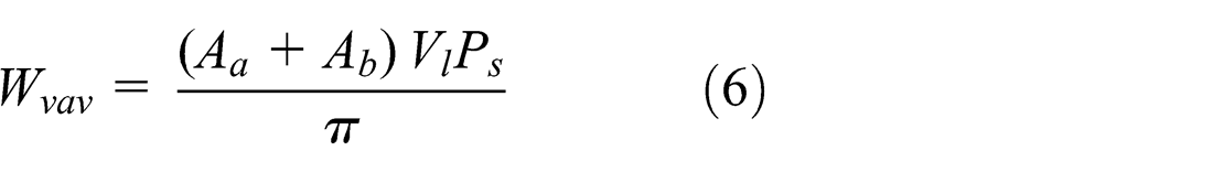
where
Conclusion
This article presented a throttle-less hydraulic circuit to control the single-rod cylinder of a tote dumper using an On/Off valve and a counterbalance valve. A counterbalance valve is a common safety hydraulic element to prevent load drifting in the case of losing the electric or hydraulic power. It was used to keep the load at a desired position with no effort from the hydraulic pump and to make system controllable when the load is assistive. Experiments were performed on a test rig which was designed and prototyped to emulate a lifting load. The accuracy of the position response of the circuit when a loop was closed on load position under a proportional controller was about ±0.034 mm. Also, energy study showed that the circuit used only 21% of energy that is required by a valve-controlled circuit to perform the same action. Experimental results demonstrated the good performance of the circuit. The proposed circuit composition was not only efficient, stable, simple, and of low cost but was also used in off-the-shelf low-maintenance industrial components. The circuit was easy to control since the only measured variable for the controller was the displacement of the actuator.
Footnotes
Appendix 1
To calculate Wh , the instantaneous delivered power by the pump to the cylinder in the case of sinusoidal motion, the motion can be described by the following equation
where
where
To lift the load, the pump provides pressurized hydraulic fluid to the rod side of the hydraulic cylinder while it receives fluid from the tank. The pump reverses the directions in case of lowering the load. The flow rate from the pump to the cylinder is given by
where
The instantaneous pump delivered power to the cylinder Wh is calculated as follows
The average pump delivered power to the cylinder
where
Therefore, the average power consumption of the proposed circuit
Academic Editor: Dr Pietro Scandura
Declaration of conflicting interests
The authors declare that there is no conflict of interest.
Funding
This research received no specific grant from any funding agency in the public, commercial, or not-for-profit sectors.