
Abstract
This study investigates the fatigue strength of anti-yaw damper brackets within a fabricated bolster specifically designed for freight locomotives. The impetus for this research arose from previous issues associated with casting bolsters, which notably lacked viscous yaw dampers—although secondary suspension snubbers contributed to overall damping—and frequently experienced failures during operation. These shortcomings highlighted the urgent need for a new design approach, leading to the development of a fabricated bolster that incorporates two anti-yaw dampers. This innovative design significantly enhances the dynamic stability of the bogie frame. To thoroughly evaluate the performance of the fabricated bolster, Finite Element Analysis (FEA) was conducted to assess both static and fatigue strength in accordance with EN 13749 standard. This analysis took into consideration various operational speeds that the locomotives might encounter. Furthermore, the integrity of the welds in the damper brackets was meticulously evaluated based on DVS 1612 guideline. The results of this comprehensive study indicate that the fabricated bolster not only improves dynamic behavior but also enhances fatigue resistance when compared to traditional casting designs. This advancement ensures greater stability and durability for locomotive operations, ultimately contributing to safer and more reliable railway systems.
Introduction
The bogie of a locomotive is an important structural member to support vehicle loading as well as carrying out most of the structural loading. The system is crucial for maintaining the alignment and stability of wheel sets on railway vehicles, ensuring safe and efficient operation. It carries the brakes, motors, gear boxes, and suspensions while sustaining the static weight of the car body. 1 In general the bogie frame of railway should have durability more than 25 years, 2 so a classical infinite life fatigue philosophy can be considered for it.
Bogie frames are always subjected to random dynamic loads when trains are running and consequently, due to service loads, fatigue may occur. A number of different calculations and experimental tests are necessary for the strength assessment of bogie frames of rolling stock. 3 In this research, a locomotive with bolster-type bogie frame has been studied as shown in Figure 1(a). This locomotive possesses unique characteristics, and its bogie features a center pivot and sidebearers. Understanding these configurations can provide insights into the stability and structural mechanisms relevant to our study. The body-to-bolster connection is facilitated by a center pivot that primarily supports the vertical load during standard operations, while side bearers provide supplementary stability. The side bearers engage only after the vertical clearance is exhausted, allowing for a smooth transition of load under extreme conditions. This understanding is essential for accurately specifying load cases, as it influences how vertical loads should be applied to the bolster.

Bogie frame and bolster (Lateral dampers are clearly indicated to illustrate their position and role within the assembly.): (a) casting bogie frame and bolster and (b) welded bogie frame and bolster with damper.
The design of the bogie is based on the lateral and longitudinal play between the bolster and bogie frame as well as between the journal boxes and guiding pedestals on the bogie frame. The bogie frame is vertically supported by six pairs of helical spring packs placed on top of the journal boxes, forming the primary suspension. Four pairs of secondary helical springs vertically support the bolster relative to the bogie frame. Damping in the bogie is primarily provided by friction. In the primary suspension, this friction is influenced by the clearances in the guiding system, and flexible pads are used to maintain contact between the components, thus determining the level of friction. For the secondary suspension, the snubbers include springs that control the damping level, allowing for adjustable performance based on operational conditions. Snubbers also transmit the longitudinal loads between the bolster and the bogie frame.
The bolster plays a critical role in welded bogie systems by facilitating load distribution. Its inclusion offers several advantages, such as design flexibility, enhanced dynamic performance, and simplified maintenance. The use of a bolster allows for optimized vibration damping and stability, which are essential for effective railway operation. The original cast bogie frame has no viscous yaw or lateral dampers, so the vibration amplitude and frequency are high enough to cause fatigue failure. This bogie frame has been in operation for more than four decades without such dampers. Because the structure is affected by wheel-rail excitation, fatigue fractures have often occurred, necessitating repairs during operation due to failures in the frame and bolster structure. The absence of dampers has had detrimental effects on its dynamic and fatigue behavior. To address these issues, a fabricated bolster and frame was designed and manufactured for this locomotive, incorporating four damper brackets for lateral and yaw dampers, as shown in Figure 1(b).
We acknowledge that the original cast bogie does not include a yaw damper, while the welded bogie described here does. However, it is important to note that a cast frame could be designed with dampers, and a welded bogie could be implemented without them. Throughout this paper, we will ensure a clear distinction between the characteristics of the bogie frame designs (cast vs welded) and the implementation of yaw dampers, as these are independent aspects of the design. Dynamic simulations conducted at different speeds have shown that the welded bogie frame with dampers exhibits greater dynamic stability than the cast bogie frame without dampers. Based on locomotive driver experience, the locomotive now has better stability and ride comfort on the track. The dynamic performance of railway vehicles is a critical aspect of their design and operation, influencing both safety and passenger comfort. Recent studies have highlighted various factors affecting this performance, particularly focusing on the role of yaw dampers and vibration control systems. Cheng et al. 4 explores the evolution of dynamic performance in the CR400BF EMU train through stochastic dynamics simulation, providing insights into how these models can predict performance under varying operational conditions. This research builds on earlier work by Huang et al., 5 who developed a mechanical model of yaw dampers, emphasizing their significance in simulating vehicle system dynamics. Further investigations into the geometric filtering phenomenon and resonant vibrations of flexible car bodies were conducted by Zhou et al., 6 shedding light on the complexities of railway vehicle dynamics. Nakajima et al. 7 contributed to this field by proposing a new mounting structure for yaw dampers aimed at reducing carbody vibrations, which was further validated by Aida et al. 8 Aida’s study not only examined the influence of yaw dampers on vertical vibrations but also verified the effectiveness of the newly developed mounting structure.
In addition to these advancements, Sugahara et al. 9 presented a vertical vibration suppression system based on primary suspension damping control, demonstrating significant improvements through vehicle running tests. Dumitriu and Dihoru 10 further expanded the understanding of vibration behavior by analyzing the impact of bending vibrations on the vertical dynamics of railway vehicle car bodies. Research by Liu et al. 11 introduced a fabricated bolster design incorporating anti-yaw dampers, significantly improving dynamic stability and fatigue resistance. Their findings indicate that modern design techniques can lead to substantial improvements in the safety and efficiency of railway systems. Additionally, Dumitriu and Stănică 12 explored the effects of anti-yaw dampers on carbody vertical vibration and ride comfort, demonstrating that these dampers not only mitigate vibrations but also improve overall passenger comfort. Together, these studies underscore the critical role of anti-yaw dampers in advancing railway vehicle design and performance. Together, these studies underscore the importance of innovative designs and simulations in enhancing the dynamic performance of railway vehicles, paving the way for improved safety and efficiency in rail transport systems. Recent advancements in railway vehicle dynamics have underscored the significance of suspension systems in enhancing ride comfort and structural integrity. Dumitriu 13 investigated the effects of asymmetry in suspension damping, revealing that optimized damping characteristics can significantly improve passenger comfort in railway vehicles. Furthering this exploration, Dumitriu et al. 14 analyzed the influence of suspension models on the vertical vibration behavior of railway car bodies, emphasizing the necessity for precise simulation techniques to accurately predict dynamic responses. Complementing these findings, Yu et al. 15 focused on strength testing and fatigue evaluation methods for bogie frames and body bolsters, proposing robust methodologies that are crucial for ensuring structural reliability under operational demands. Additionally, Stanica and Dumitriu 16 conducted a numerical analysis to identify critical points affecting ride comfort in flexible railway car bodies, further highlighting the importance of structural considerations in dynamic performance assessments. Lastly, Huo et al. 17 introduced stiffness-adjustable anti-yaw dampers, presenting innovative solutions aimed at enhancing stability and mitigating vibrations in railway systems. Collectively, these studies contribute to a comprehensive understanding of the interplay between design, materials, and dynamic behavior in railway vehicle systems, paving the way for improved safety and performance.
Recent studies have highlighted the critical importance of understanding the fatigue behavior and dynamic performance of bogie frames under varying operational conditions. Sun et al. 18 estimated fatigue stress in bogie frames using frequency response functions derived from limited sensor data, emphasizing the role of dynamic loads in fatigue life assessment. Additionally, Wang et al. 19 conducted a comprehensive investigation into the vibration environment spectrum at the ends of bogie frames, revealing how environmental factors contribute to structural integrity. Li et al. 20 further advanced this field by applying a one-dimensional convolutional block residual channel attention model for fault diagnosis in high-speed train components, underscoring the significance of accurate monitoring for enhancing safety and performance. Moreover, Sun et al. 21 examined the influence of rail weld irregularities on dynamic stresses within bogie frames, utilizing a vehicle-track rigid-flexible coupled model to simulate realistic operational scenarios. Collectively, these studies underscore the necessity for innovative assessment techniques and design modifications to improve the durability and reliability of bogie frames. Additionally, Pagaimo et al. 22 proposed transmissibility-based methods for damage identification in railway bogie frames, offering innovative techniques to detect cracks and enhance structural monitoring, which aligns with our focus on fatigue resistance in fabricated designs. Furthermore, Bustos et al. 23 examined the effects of secondary suspension stiffness, including longitudinal dampers, and intercar links on the critical speed and oscillations of high-speed passenger trains, providing insights into damper configurations that improve vehicle stability and ride quality.
The main novelty of this paper lies in the development and comprehensive evaluation of a fabricated bolster design for a locomotive bolster-type bogie frame that integrates anti-yaw dampers, addressing longstanding failures in traditional casting bolsters that lacked such damping mechanisms and were prone to operational fractures. While the study has strong industrial applications, its research contributions extend beyond by pioneering a systematic approach that combines advanced vehicle dynamic simulations using Gensys software—incorporating realistic wheel-rail interactions, varying friction coefficients, and track irregularities, followed by finite element analysis (FEA) for static and fatigue strength assessment according to EN 13749, and weld integrity evaluation via DVS 1612 guidelines. This not only demonstrates significant improvements in dynamic stability (e.g. reduced Y-forces and S-forces by factors of 2–3 at higher speeds) and fatigue resistance compared to cast designs but also contributes to the state of the art by providing a validated framework for redesigning legacy bogie systems, enabling higher operational speeds on compliant tracks, and offering empirical insights into damper implementation that can inform future standards and simulations in railway engineering, as evidenced by our comparative analyses and experimental validations.
This study conducts an extensive dynamic performance analysis of the modified bogie, utilizing advanced simulation techniques to assess its behavior under various operational conditions. The results demonstrate significant improvements in stability and response characteristics compared to conventional designs, while maintaining a focus on cost-effectiveness and minimal alterations to the existing configuration.
Finite element model, boundary conditions and constraints
The model consists of sheet metals which connected through welding. The former design of the bolster was casting. Figure 2 shows the coordinate system used in these structural analysis. The structural analysis is performed using the finite element method with a linear elastic material behavior. Finite element simulations were performed using HyperWorks as the modeling platform, with OptiStruct as the solver, ensuring accurate assessment of bogie frame stresses under EN 13749 loads. The loads and boundary conditions are applied to the FEA model. The FEM model consists of 769,184 elements and 1,275,499 nodes which most of the elements are second order Tetrahedron. The size of elements is about 10–15 mm, which are smaller in critical or curve-shaped areas. Moreover, 4 CBUSH and 21 RBE3 elements have been used in the model. As well as no RBE2-elements have been used in the simulation of the bolster. The boundary conditions for the analysis of the bolster are realized by a simplified but realistic representation of the secondary suspension as shown in Figure 2. The secondary suspension is represented by four spring elements (one per spring pair). One node of the spring is used for constraining the model, the other one is connected by a RBE3-element with the bolster.

Finite element model of the bogie bolster (including the system of coordinates for the strength analysis of the bolster and the boundary conditions for all load cases).
Material data
The bolster is made of steel plates and cast steel parts. Figure 3 shows the locations of the cast parts made of G20Mn5+N as well as the steel plates made of S355J2W+N within the bolster.
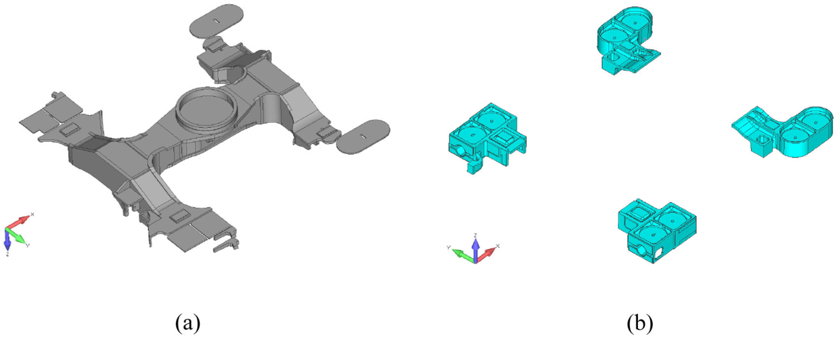
Materials used for the bolster: (a) parts made of steel plates grade S355J2W+N in the bolster and (b) cast parts made of G20Mn5+N in the bolster.
Material data for steel plates
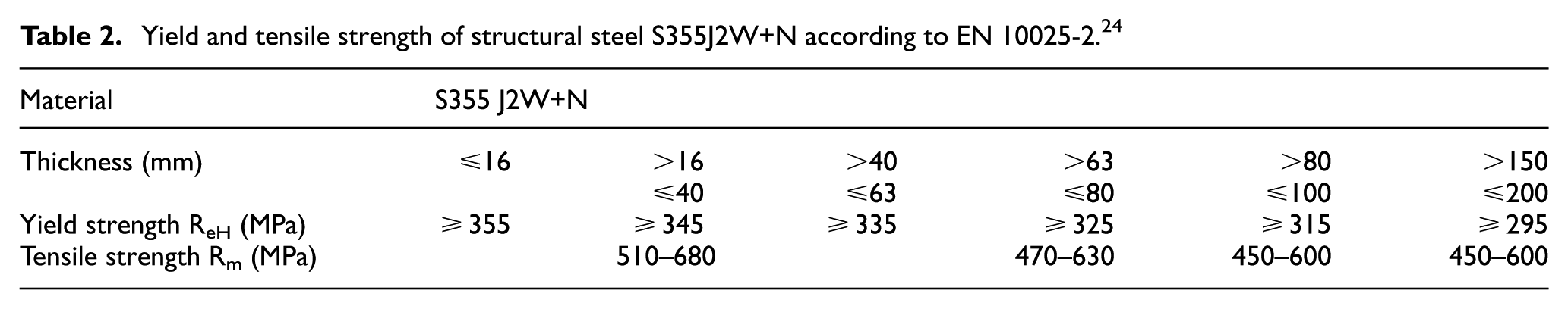
The physical properties used for the FE-analysis are listed in Table 1 while the yield and tensile strength of the base material is given in Table 2 respectively.
Physical material properties of structural steel S355J2W+N used for the structural analysis.

Yield and tensile strength of structural steel S355J2W+N according to EN 10025-2. 24
Material data for casting parts
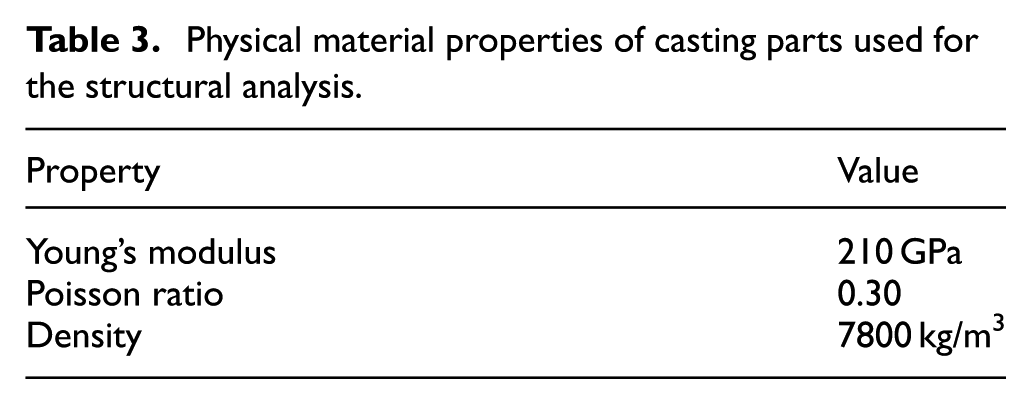
The casting parts included in the bolster are made of G20Mn5 +N according to EN 10213. 25 The physical properties used for the FE analysis are listed in Table 3, while the yield and tensile strength according to FKM-guideline 26 of the casting material are given in Table 4 respectively. The strength reduction through material thickness is considered by a thickness factor according the FKM guideline. This factor is defined for cast parts from G20Mn5+N with a thickness above 30 mm as:

An effective thickness (deff) of 50 mm is used.
Physical material properties of casting parts used for the structural analysis.
Yield and tensile strength of casting parts made from G20Mn5+N.

Application of loads
Load assumptions and boundary condition of anti-yaw damper bracket
In the Figure 4 examples of the load application by RBE3-elements to the solids elements of the FE model is shown. In this figure, the solid element edges are not shown for a better visibility of the load introduction and the load vectors. In general, the applied loads are unit loads based on their definition in the load assumptions. Figure 4(a) shows the RBE3-elements on one bolster side used for the load application of the longitudinal stop forces during forward driving. Figure 4(b) shows the load acting on the lateral bump stop on the right side of the bolster.

Load applications: (a) load application element (RBE3) for the introduction of the longitudinal stop force—forward, (b) load application of the lateral bump stop in left direction, and (c) all RBE3-elements used in the FE-model.
Due to the specific design of the locomotive, the load assumptions include loads from EN 13749 27 category B-V (loads for freight bogies with a central pivot and two side frames) and EN 13749 category B-VII (loads for bogies of locomotives).
The standard EN 13749 Annex C provides guidelines for load distribution in 3-axle bogies with a central pivot and side-bearers, which are directly applicable to our locomotive design. According to the annex, vertical loads are typically distributed equally across all three axles in symmetric configurations, while longitudinal and lateral loads are distributed with 37.5% on each outer axle and 25% on the central axle. However, in our bogie, the distances between the central axle and the outer axles are not equal, necessitating an adjustment to the vertical load distribution to achieve a set of equilibrium loads under static conditions. This customized distribution ensures accurate representation of the forces experienced by the bogie during operation.
The vertical load is applied to the bolster and the bogie frame. The secondary springs will have the load corresponding to when the vertical stops make contact and the load is distributed accordingly.
The standard EN 13749 stipulates that a longitudinal force is applied to each wheel in such a way that the forces constitute a shear load. The wheel loads on one side of the bogie is applied in the opposite direction as compared to the other side. The other longitudinal force corresponds to inertia force under an acceleration of 3g. This is valid for motor bogies for vehicle categories B-I and B-II. For locomotives of category B-VII it is stipulated that a shock test should be performed. A wagon is run into the locomotive and the maximum acceleration in such a collision is used to be multiplied with the bogie mass to give the dimensioning longitudinal load. The assumption to use 3g is used.
With a vertical exceptional load state the bogie frame should withstand the loads resulting from a track twist of 1%. It must also withstand the loads resulting from 1% track twist when exposed to lateral exceptional load state. Twist 1% is defined as follows. The rail on one side is straight and horizontal and the rail on the other side is given a vertical slope so that the outermost wheels are positioned with a difference of 1% of the axle distance vertically. For the normal service loads according to EN 13749, the bogie frame should withstand the loads resulting from a track twist of 0.5%. This twist load is half of the 1% twist load for exceptional loads and is close to what is stipulated for a transition curve in EN 14363.
The EN 13749 standard specifies load cases corresponding to loads resulting from bogie running. The load cases relate to cases that can easily be tested with regard to load application. Roll and bouncing which include quasi-static and dynamic variations of vertical forces are represented by coefficients α and β, respectively. Generally these coefficients values are 0.1 for α and 0.2 for β.
Vehicle dynamic simulations
The objective was to compare the welded bogie frame and bolster with the original cast frame and bolster. The weight of the cast bogie frame is 3300 kg and the weight of the welded frame is approximately 700 kg more or 4000 kg. The weight of the cast bolster is 1300 kg and the weight of the welded bolster is approximately 1800 kg. The study includes the cast configuration, which utilizes a traditional cast bogie frame and bolster; the welded configuration without a damper; and the welded configuration with a damper, which also features welded components but incorporates damping mechanisms to enhance stability and ride quality. Each configuration is evaluated under specific conditions, including track irregularities and varying speeds, to assess their performance and characteristics effectively. This comparative analysis aims to highlight the advantages and limitations of each setup in practical applications. The three different vehicle configurations are simulated on a straight track (tangent track) with track irregularities classified for 120 km/h. The vehicles have new and worn wheels. The speed is 90, 105, and 120 km/h. The locomotives are simulated without traction and with 240 kN nominal traction. The differences between new and worn wheels extend beyond diameter: new wheels follow the AAR G-29 standard profile with a 1016 mm diameter, while worn wheels, measured from operational GT26 locomotives at Mapna Locomotive, feature a reduced diameter of 916 mm and a modified profile due to natural wear, including tread flattening, increased flange height, broader rail-wheel contact distribution, and limited flange contact. This “beautifully worn” shape enhances adaptability to track irregularities but also alters contact geometry, leading to higher equivalent conicity and increased instability risks, such as elevated S-forces, Y/Q ratios, lateral forces, and hunting behavior.
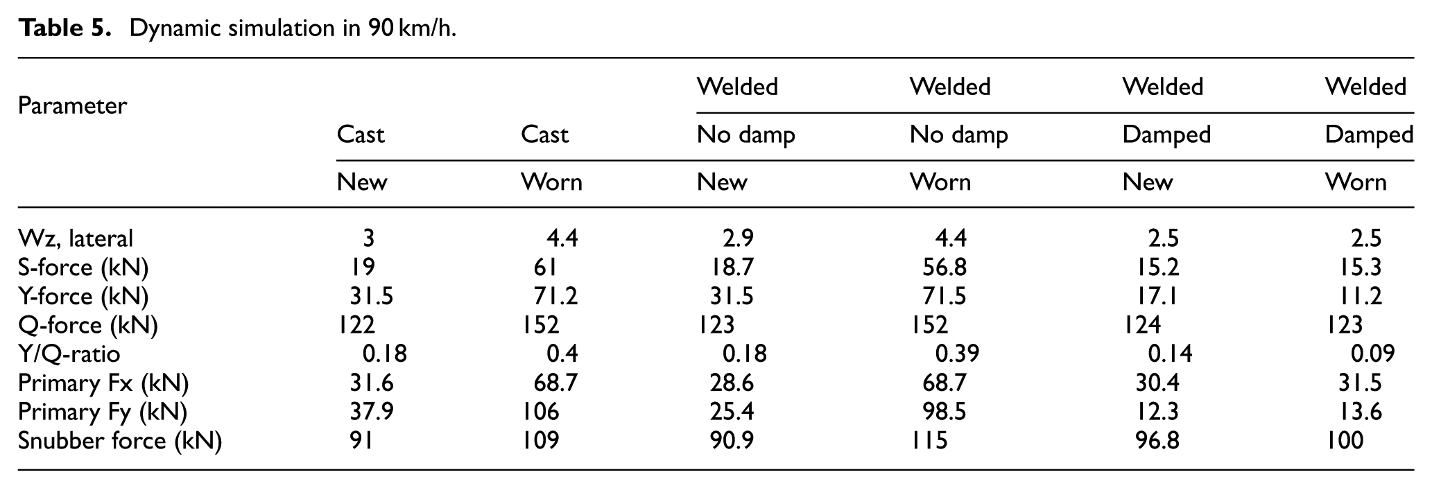
The GT26 series locomotive, a 6-axle diesel-electric model utilized in this study, has a maximum operating speed of 105–150 km/h depending on variants, gearing ratios (e.g. 62:15 limits some to ∼105 km/h, while others reach 124–150 km/h), and applications such as heavy-haul freight. However, the analysis of the original cast bogie frame without dampers revealed significant dynamic instability, leading us to recommend limiting its operational speed to no higher than 85 km/h to prevent failures. The dynamic simulations, as detailed in Tables 5 to 7, were conducted at 90, 105, and 120 km/h to evaluate the enhanced performance of the new fabricated bolster design with integrated anti-yaw dampers. These simulations assessed realistic operational conditions—such as speeds of 80–120 km/h on regional tracks or 113 km/h in 600 m curves—along with compliance to EN 13749/14363 standards for bogie loads and stability (e.g. Y/Q ratios up to 0.64 and S-forces to 60 kN), ride comfort, and comparisons between welded (frame 4000 kg, bolster 1800 kg) and cast (3300, 1300 kg) configurations under new/worn wheels and damped/undamped conditions. The results demonstrate that the new design enables safe and stable operation up to 120 km/h on European-standard-compliant tracks, surpassing the original design’s safe limit of 85 km/h while staying below the locomotive’s maximum speed of 150 km/h, with no primary simulations exceeding this threshold.
Dynamic simulation in 90 km/h.
Dynamic simulation in 105 km/h.

Dynamic simulation in 120 km/h.

The vehicle dynamic simulations were conducted using the software Gensys, which is well-suited for analyzing locomotive bogie dynamics and vehicle-track interaction. The Gensys simulations model the complete locomotive, including two 3-axle bogies and carbody, to evaluate bogie dynamics (e.g. Y/Q ratios, S-forces) under operational conditions (90–120 km/h).
The simulations included both new and worn wheel profiles. The wheel profile used corresponds to the AAR G-29 standard, with new wheels having a diameter of 1016 mm and worn wheels down to 916 mm. The rail profile simulated was the standard UIC 60 rail with a 1:20 inclination, compliant with European track standards for speeds up to 120 km/h. Wheel-rail contact geometry was carefully modeled, taking into account flange contact, particularly in curves with radii as low as 600 m where flange contact occurs, resulting in wear considerations.
The contact model used is embedded within the Gensys simulation framework. The simulation computes contact pressures, wheel-rail force distributions, and contact patch segmentation consistent with validated wheel-rail interaction models to realistically capture ride stability and wear behavior. In the dynamic simulations, taper matching between the wheels and rails was considered essential for accurately assessing the performance of both new and worn wheel conditions. Taper matching refers to the geometric alignment between the wheel profile and the rail profile, which significantly influences the contact dynamics and stability of the bogie frame. The software addresses the taper matching problem using equations based on Hertzian or non-Hertzian models, which utilize theories such as Kalker to study this phenomenon. One of the key differences between multibody software, compared to other software, is that it incorporates taper matching equations at every moment of contact between the wheel and the rail. Additionally, in multibody software, ready-made models are provided for wear, allowing for a more realistic simulation of the dynamic behavior under varying operational conditions.
The simulated coefficient of friction between the carbody and the bolster at the center pin was set to 0.05 (5%) for most simulations representing nominal yaw damping conditions. Additional simulations were performed with increased yaw damping using a friction coefficient of 0.45 (45%) to demonstrate stability improvements. These friction values were applied at an effective radius of 173 mm.
Simulations were run at 120 km/h on tangent (straight) track and approximately 113 km/h in a 600 m radius curve, with track compliant to European standards. The lateral axial play gap was set to nominal GT26 bogie values (22 mm total on all axles) and reduced gap configurations (down to 3 mm) were also simulated to study effects on stability. Initial conditions included a short straight approach section to the curve to capture transient behavior on entering curved track.
Conclusions from vehicle dynamic simulations on tangent track
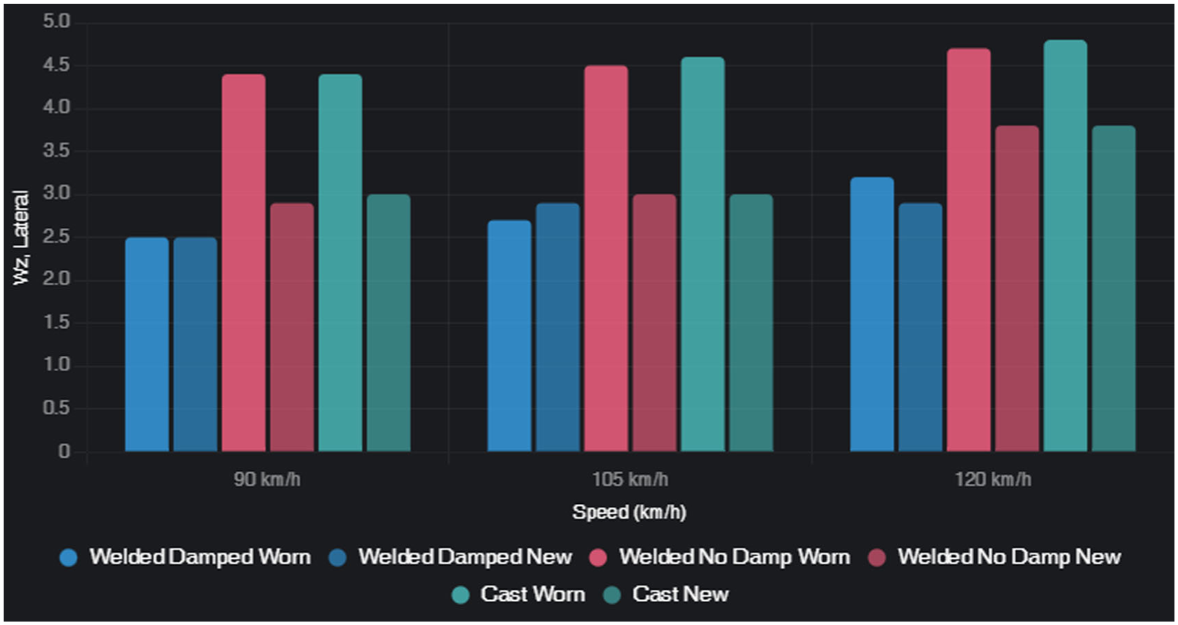
Traction stabilizes the dynamics of the locomotive. In 90 km/h all different locomotive configurations, except for the locomotive with cast frame and bolster, generate S-forces below the limit according to Prud’homme’s formula. The S-force is defined as the difference between the lateral forces on the left wheel and the right wheel. The S-force is the track shift force or the force between a wheel-set and the track. Locomotives without viscous damping generally generate too high Y-forces. Y-force accounts for lateral forces between the journal box and the pedestals on the bogie frame. This force is given in kN and can occur on either the left side or the right side. The value accounted for is the highest found in the simulations. The locomotive with cast bogie frame and bolster has similar characteristics as the locomotive with welded bogie frame and bolster when no damping is present. Both S-forces and Y-forces are below limits when the locomotive has welded bogie frame and bolster and optimized yaw and lateral viscous damping. A summary of highest found lateral comfort Wz-values, forces, and Y/Q ratios are accounted for in the following tables. The tables are given for the speed 90, 105, and 120 km/h. The highest vertical Wz-value is 2.6 when the speed is 90 km/h for all locomotive configurations. The vertical Wz-value is less than 2.8 when the speed is 105 km/h. In the speed of 120 km/h the vertical Wz-value is less than 3.0.
In 90 km/h the S-force limit is exceeded by the original locomotive with worn wheels. The Y-force limit is exceeded by more than a factor 2 for locomotive configurations without viscous damping. The Y-force limits are typically based on standards set by organizations such as the American Railway Engineering and Maintenance-of-Way Association (AREMA) or the International Union of Railways (UIC). These standards provide guidelines on acceptable force limits for railway vehicles to ensure safety and structural integrity during operation. The specific limits can vary depending on the type of locomotive, intended use, and operational conditions, but exceeding these limits by a factor of 2 indicates a significant concern regarding the performance and durability of the locomotive under the given conditions. The locomotive with optimized viscous yaw and lateral damping the S-forces and Y-forces generate low force levels. The highest longitudinal loads on the pedestals can be considered to be below 70 kN. The longitudinal load on one pedestal will vary from 0 to 70 kN. The highest lateral load between one journal box and two pedestals can be considered to be not higher than 110 kN. The lateral load may be considered to be equally distributed on the pedestals and will vary from 0 to 55 kN. The snubber load is not higher than 120 kN between one snubber and the bogie frame.
The loading in 105 km/h generates higher loads. Locomotive configurations without viscous damping and with worn wheels exceed the Y-force limit by a factor 3. S-forces are also exceeded for the same locomotive configurations.
It should be noted that the force values presented in section “Conclusions from vehicle dynamic simulations on tangent track” were derived from the simulated time histories obtained during the dynamic analysis of the GT26 locomotive bogies. These values represent the maximum forces recorded throughout the simulations, which were performed using Gensys software under various operational conditions. The simulation data captures the peak loads experienced by the bogie frame, reflecting both the influence of different configurations (such as cast vs welded frames) and the dynamic interactions during operation.
Dynamic results are evaluated against EN 14363 limits: Y/Q ≤0.8 (quasi-static), ΣY ≤78 kN (Prud’homme), Q ≤145 kN (dynamic). For cast worn at 120 km/h, Y/Q = 0.64 (safe), but ΣY = 89 kN and Q = 165 kN exceed limits, underscoring the need for dampers. The graphical representations of these tables, which allow for a more visual comparison of the dynamic stability metrics, can be seen from Figures 5 to 9.

Dynamic simulation at 90 km/h—force parameters.

Dynamic simulation at 105 km/h—force parameters.

Dynamic simulation at 120 km/h—force parameters.

Y/Q-ratio (stability indicator) across speeds.
The locomotive with casting bogie frame should never be used for higher speed than 85 km/h. The locomotive with welded bogie frame and bolster and no viscous damping generates approximately the same loads and as a consequence the speed should be limited to 85 km/h. The recommendation that the locomotive with the original cast configuration should not exceed 85 km/h originates from prior operational assessments, which evaluated the bogie without lateral or anti-yaw dampers and found critical hunting speeds as low as 90–100 km/h in certain configurations, with excessive Y-forces, S-forces, and Y/Q ratios exceeding permissible limits (e.g. per EN 14363 and Prud’homme criteria) even on straight tracks, alongside poor ride comfort indices (indicating unacceptable lateral comfort, especially with worn wheels).
The locomotive with welded bogie frame and bolster with optimized viscous yaw and lateral damping can be used for a speed of 120 km/h. This is based on the important condition that the track standard complies with the European track standard for 120 km/h, specifically referencing the EN 13848 series, which outlines the requirements for track geometry and quality. High track irregularities can result in high effective coincide between the wheel and the rail when worn wheel profile is used. Worn wheel profiles typically exhibit high equivalent conicity, which reduces the critical speed at which hunting instability can occur. The simulations show that high track irregularities can also initiate unstable running in vehicles with worn wheels. This happens because irregularities induce larger lateral displacements of the wheelsets, causing them to operate in regions of the wheel profile where conicity is higher due to the nonlinear profile shape. This will start unstable run and the energy needed to stabilize the bogie may not be provided by the viscous dampers. It is interesting to notice that the damping loads are low when the bogies run stable.
Welded regions of the bolster
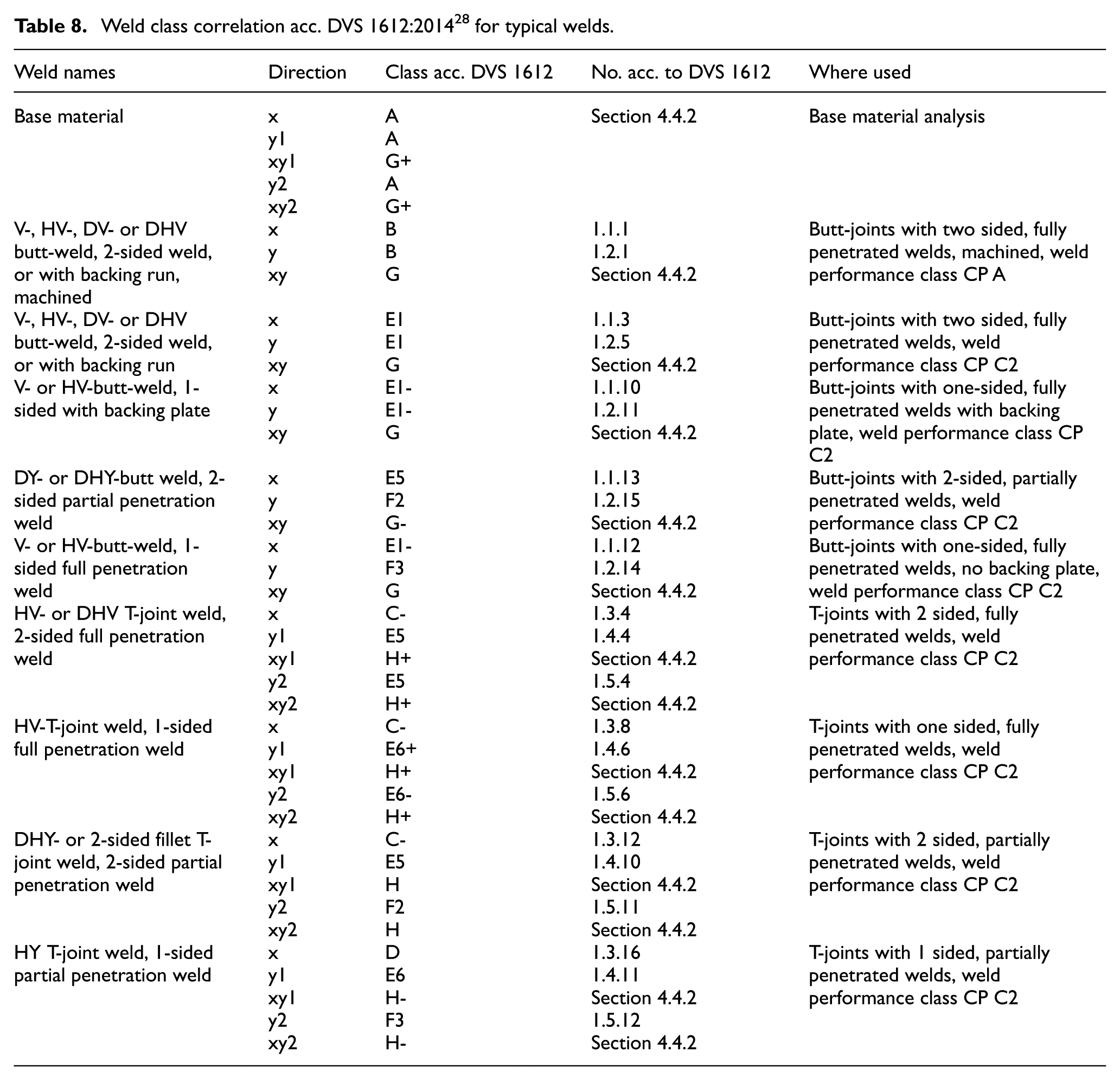
Figure 10 shows the welds assessed in the bolster based on the weld drawings which show the anti-yaw damper weld region in red circle. The bracket weld seams are one and two sided T-joint with partial penetration welds. The weld classes are indicated in Table 8. Fatigue strength simulations utilized weld material properties from the DVS 1612 guideline, differing from the base metal sheets of the bolster, to reflect their unique fatigue characteristics under EN 13749 loads.

Weld regions.
Weld class correlation acc. DVS 1612:2014 28 for typical welds.
Fatigue strength analysis
The proof of sufficient fatigue strength is established as follows: First, the fatigue loads according to the load assumptions are applied to the FE-model. Based on these stress results, the load combination producing the highest stress range for every node is calculated. The fatigue evaluation at each element of the FE-model is in respect to all the load case groups. The maximum stress range is evaluated for each element and component according DVS 1612 within each load case group. Subsequently, the usages are calculated based on these nodal stress levels according to DVS 1612.
In practice, peak stresses causes the fatigue damage, so it should be reminded that it is different from averaging process. Because of the need to retain peak stress values, un-averaged nodal results has been used instead of averaged nodal, or element-Gauss values. Element-Gauss values are usually specified away from peak stress values. 29
Fatigue analysis using higher order elements may lead to better and more accurate results. High attention has been taken about the aspect ratio of the elements. 29 Fatigue endurance strength related to peak combined stress obtained from EN 13749 loads are assessed using the DVS 1612 guideline. Fatigue analysis has been done for 127 load combinations based on the loads derived from EN 13749.
According to DVS 1612, allowable nominal stresses for an extensive catalogue of structural weld details classified in the strength classes A, B, C, D, E1, E5, E6, F1, F2, and F3 can be determined, whereas class A corresponds to base material strength. The first step of the fatigue assessment is the base material assessment according to DVS 1612 by using the fatigue class A. However, it is important to be aware that this fatigue class A requires all the components to be laser cut or machined. Torch cutting of the plates is not allowed for the use of this fatigue class.
For all welds, the notch case line for the different stress components are defined based on the weld type. Stress results obtained by Finite Element Analysis include stress concentrations at discontinuities. In order to obtain an estimate of the nominal stresses in welds, the stress values at a distance of 1–1.5 times the plate thickness from the weld toe are used, as proposed in DVS 1612. However, smaller offsets have sometimes to be chosen due to small overhangs. In case that the weld utilization is within the allowable limits, sufficient strength is given. The allowable maximum stresses depend on the weld performance class and stress ratio
In general, for parts manufactured of S355 or welds connecting such parts, usages below 1.0 are acceptable. Areas with high usage values shall be carefully manufactured. Corresponding requirements for the weld performance class (CP A to CP C2) are included in the tables of DVS 1612. For all welds, which have a smaller weld section then the two connected components, the usage needs to be scaled as described before.
According to the DVS 1612, the fatigue limits of the welds which connect other materials then S355, must be adjusted relative to the ratio of the yield strength of the material to yield strength of S355. In the case of weld connections on cast parts made from G20Mn5 this means a maximal usage of 0.84 is allowed (
The fatigue strength of casting parts is assessed according to the FKM guideline. According to the FKM guideline a safety factor of 2.0 (1.4 for non-inspected cast material and 1.4 for medium consequence of failure in combination with high probability of occurrence of the characteristic stress values) and a surface roughness of 200

Fatigue U.F. for bolster base material.
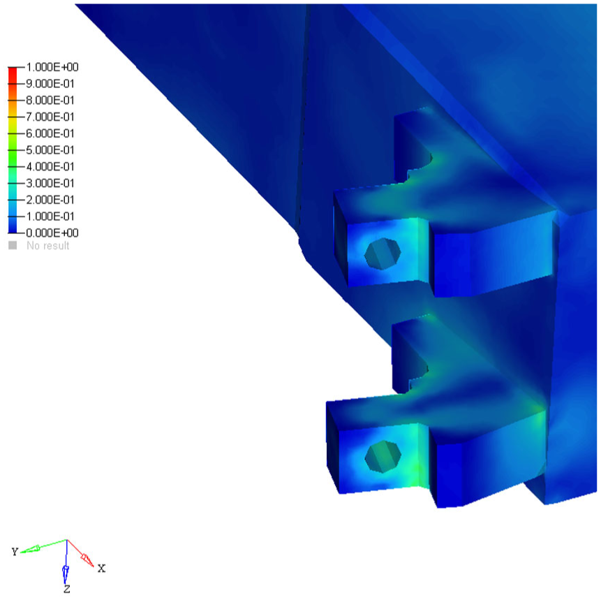
Fatigue strength analysis for damper bracket front view.

Weld fatigue analysis for welded line front view.

Weld fatigue analysis for welded line back view.
It should be noted that the utilization factor (U.F.) is represented within the range specified by the EN 13749 standard, which utilizes a scale of 0–1.
Test description
The test aims to confirm the structural soundness of the bogie frame and assess its capacity to endure both proof loads and operational loads. Additionally, it will facilitate the validation of the strength analysis conducted. By performing this test, potential issues in the bogie production process can be detected at the initial stage, while design flaws can be identified in the subsequent stage. Consequently, this procedure is essential for any new production line or any frame featuring a novel design.
According to EN13749 standard, the static tests are deemed successful when no cracks are observed and all recorded stresses remain below the maximum allowable stress values specified for each section of the frame (such as base material and welds). If stresses exceed these allowable limits, the tests can still be considered successful if the following criterion for residual strain is met:
Residual strain after unloading ≤0.05 × material yield stress/Young’s Modulus
Consequently, both the stress values and the residual strain must be documented in the test report. Throughout the static tests, the yield strength was not surpassed in any loading scenario, and the residual stress values were found to be minimal across all measurements. Following the static tests, a non-destructive magnetic powder test was conducted, revealing no signs of issues.
The bogie frame is regarded as sufficiently robust, and the fatigue test is considered successful if no cracks are detected after the first two phases. Minor cracks are permissible during the third phase, provided they do not necessitate immediate repairs to the bogie frame in service.
A schematic of the loads is presented in Figure 15 and an overview of the overall layout of the test setup is shown in Figure 16.

Test schematic of the loads.

Test setup overall layout.
Prior to testing, the bogie frame was inspected for cracks. Different test frequencies were evaluated to determine the optimal rate that balanced test stand stability with sensor performance. The effects of increasing the test frequency were assessed by comparing the results to those obtained at a very low frequency. Throughout the testing process, continuous visual inspections were performed to detect any potential crack formation. An NDT inspection was conducted before the fatigue test to confirm whether any damage had occurred during the earlier static tests.
This research extensively examined the static and fatigue strength of the bogie frame using finite element analysis and stringent testing methods. The results indicate that the bogie frame complies with the EN 13749 standard, showcasing sufficient performance across different loading scenarios.
Static testing validated the analytical findings, revealing that the yield strength was not surpassed and that residual stresses were minimal. Nonetheless, higher stress levels were detected at certain points, which should be addressed in future design efforts. Non-destructive testing affirmed the frame’s integrity, with no major defects found.
In summary, this thorough evaluation highlights the necessity of detailed static and fatigue assessments to ensure the reliability and safety of railway components. The knowledge gained from this research not only enhances the understanding of the bogie frame’s performance but also lays a foundation for future studies and advancements in bogie design.
Comparison of FEM and experimental results
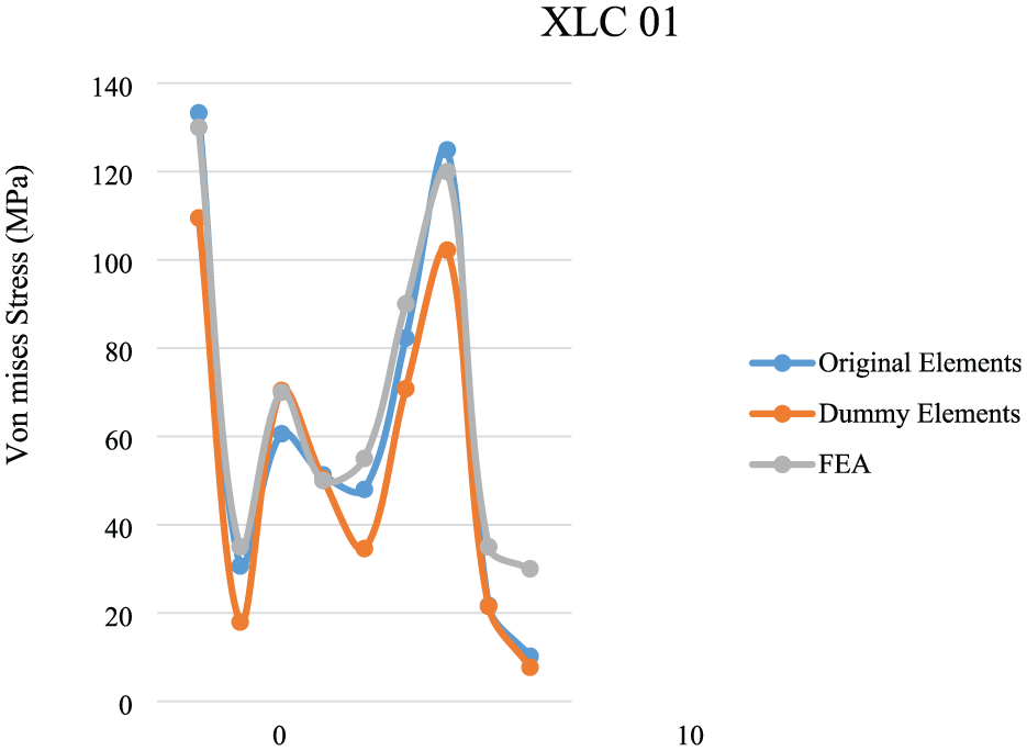
In this research, a thorough comparison was made between the findings from finite element modeling (FEM) and those obtained through experimental testing of the bogie frame. The FEM analysis employed sophisticated computational methods to simulate the frame’s structural response under different loading scenarios, while the experimental tests were carefully designed to reproduce these scenarios in a controlled setting. The experimental findings are compared with the simulation data at the specified location, serving as the control point for strength assessment. The graphs illustrating the comparison for various load cases can be found in Figures 17 to 21. It should be noted that the dummy elements, used in bogie fatigue testing, replace original primary and secondary helical springs with rigid substitutes like solid plastic cylinders or steel cylinders with spherical joints to facilitate reasonable test frequencies and avoid instability from compliant springs. Static pre-tests compare setups with original and dummy elements to assess their impact on stress distribution and fatigue strength. Axles are also substituted with dummies for applying constraints and twist loads, while tension rods are retained to simulate lifting stops and residual stresses.
Comparison between FEM and experimental test result for the 1st load case.

Comparison between FEM and experimental test result for the 5th load case.

Comparison between FEM and experimental test result for the 9th load case.
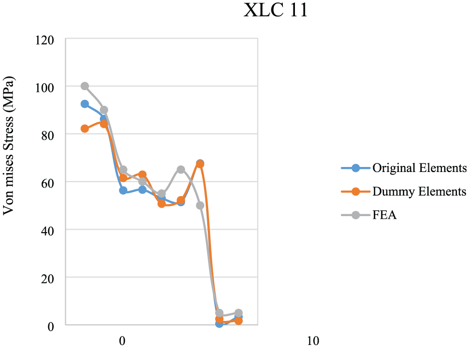
Comparison between FEM and experimental test result for the 11th load case.
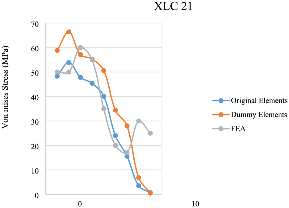
Comparison between FEM and experimental test result for the 21st load case.
All loads are extracted from the requirements of EN 13749 standard. The correct combination of these loads have been evaluated for the analysis, which can be seen in Table 9.
Exceptional loads according to the table F.2.1.

It should be noted that the horizontal axis represents specific random points in the hot spot regions that are crucial for comparing both the analytical results and experimental tests. The choice of specific random points along the horizontal axes of the figures, located within the hot spot regions, was driven by the need to focus on areas of the bogie frame and bolster most susceptible to fatigue and stress concentration, as identified through initial stress analyses. These hot spots, represent critical locations where experimental validation is most relevant to ensure the FEM model’s accuracy. The same hot spot regions are analyzed in all load cases.
As a sample case, the analysis results of stress in different parts of the bogie frame for these load cases are shown in Figures 22 to 26.

Stress analysis results for XLC 01.
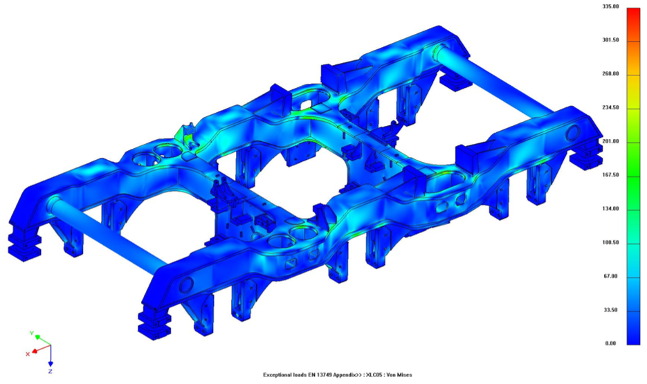
Stress analysis results for XLC 05.
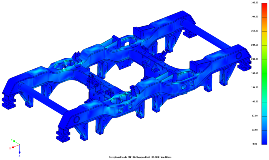
Stress analysis results for XLC 09.

Stress analysis results for XLC 11.

Stress analysis results for XLC 21.
The outcomes from both methods showed a strong correlation, confirming the accuracy and reliability of the FEM approach. In particular, the stress distribution patterns seen in the FEM simulations were closely aligned with those observed in the experimental tests. This consistency not only enhances the credibility of the FEM analysis but also provides confidence in its ability to predict future design iterations. Important metrics, such as peak stress levels, were closely aligned, with differences remaining within acceptable ranges. This strong correlation suggests that the FEM model accurately reflects the key mechanical behavior of the bogie frame, facilitating informed decisions in design and optimization processes. The favorable comparison between FEM and experimental findings underscores the effectiveness of finite element analysis as a valuable tool in structural engineering, facilitating precise and efficient evaluations of bogie frame performance.
Conclusions
This study presents a comprehensive investigation into the static and fatigue strength of anti-yaw damper brackets within a fabricated bolster designed for freight locomotives. Through innovative design modifications and the integration of anti-yaw dampers, the research addresses the critical issues associated with traditional casting bolsters, which have historically suffered from fatigue failures and inadequate dynamic stability. The findings from the Finite Element Analysis demonstrate that the newly fabricated bolster significantly enhances the dynamic behavior and fatigue resistance compared to its casting counterparts. By adhering to the EN 13749 standards, this research not only validates the structural integrity of the fabricated bolster but also establishes a robust framework for evaluating the performance of locomotive components under various operational conditions. The incorporation of anti-yaw dampers has been shown to markedly improve the dynamic stability of the bogie frame, leading to enhanced operational efficiency and safety. The fatigue analysis confirms that the fabricated design withstands cyclic loading effectively, with no significant fatigue issues identified in both the base material and welds. The weld integrity assessment, following DVS 1612 guidelines, further corroborates the reliability of the constructed components. In terms of the weld seams, the bolster has been shown to provide adequate strength across all fatigue load scenarios. This comprehensive analysis confirms that the structural modifications proposed for the damper brackets are not only feasible but also will not introduce any fatigue strength issues into the overall structure. The results underscore the importance of adopting fabricated designs and optimized welding techniques in future locomotive systems. The successful implementation of these strategies can lead to improved performance, extended service life, and ultimately, safer railway operations. In conclusion, the advancements presented in this study not only contribute to the body of knowledge surrounding locomotive bogie design but also pave the way for future innovations in railway vehicle dynamics. The effective application of modern engineering principles in the development of fatigue-resistant components is crucial for addressing the evolving demands of railway transport, ensuring reliability, safety, and enhanced passenger comfort.
Footnotes
Handling Editor: Chenhui Liang
Funding
The author received no financial support for the research, authorship, and/or publication of this article.
Declaration of conflicting interests
The author declared no potential conflicts of interest with respect to the research, authorship, and/or publication of this article.