
Abstract
This paper proposes a novel polarity variation control strategy for six-phase switched reluctance motors (SRMs). The magnetic pole distribution characteristics under three-phase conduction are analyzed, revealing that an NSN pole arrangement yields higher starting torque. Comparative analysis of winding topologies demonstrates that only a reverse-series winding with alternating NS poles can produce a three-phase NSN configuration. However, this winding configuration exhibits significant inter-phase coupling, resulting in compromised fault tolerance. The proposed control strategy enables a forward-series connection with alternating NS pole arrangement, which ensures phase decoupling while enhancing fault tolerance and output performance. Simulation and experimental results demonstrate that this control method enhances the symmetry of phase currents, increases torque output, and reduces torque ripple.
Introduction
With the increasing number of fuel vehicles, energy and environmental issues have progressively intensified. Electric vehicles (EVs), boasting advantages such as cleanliness and high efficiency, have emerged as a viable solution. In particular, the unique environmental benefits of electric vehicles have positioned the development of EVs as the mainstream focus of green vehicle research worldwide.1–4
The electric motor, as a fundamental component of EVs, must meet specific performance standards. It not only encompasses the general electrical characteristics but also adapts to the demanding operating conditions of automobiles. Consequently, traction motors require high power density, efficiency, fault tolerance, and cost-effectiveness.5–7
Switched reluctance motors (SRMs) are characterized by a simple, rugged rotor without windings or PMs, and independent phase control. These advantages make SRMs promising candidates for Evs applications.8–13 SRMs are designed to be competitive with the IPMSM employed in HEVs in References 14–16, the results show that the shaft output can be enhanced by 160% in SRMs. However, the main drawbacks of SRMs are high levels of torque pulsation and acoustic noise,17–21 for this reason, there are no household EVs with an SRM drive in the market. To address these issues, considerable research has been conducted on both motor topologies and control algorithms. Among various approaches, multi-phase SRMs show particular promise, as they can reduce torque ripple while improving system fault tolerance compared to traditional three-phase designs.22–24
Phase windings in conventional SRMs can be connected through either forward or reverse series configurations. In conventional SRMs, the winding connection method significantly influences magnetic symmetry and inter-phase coupling. In odd-phase machines such as three-phase SRMs, a forward-series connection of the windings produces a symmetrical magnetic field with negligible mutual inductance between phases. By contrast, even-phase machines such as six-phase SRMs exhibit symmetrical magnetic fields under reverse-series connection. However, this configuration introduces mutual inductance between phases, thereby compromising system robustness. Several decoupled winding connections are proposed and compared in Medina-Sánchez et al.25,26 and Yepes et al., 27 however, the magnetic field is unsymmetrical in decoupled winding connections, and the winding connection is not the optimal choice across the whole speed range.
While prior studies have established the benefits of multi-phase SRMs for torque ripple reduction and fault tolerance, challenges remain in balancing high performance with phase decoupling. This work addresses these challenges by proposing a novel polarity control strategy that leverages forward-series windings to achieve optimal magnetic pole arrangements without compromising phase independence. In this paper, the SRM is designed for EVs, based on the requirements of EVs, emphasizing the necessity for reduced torque ripple and enhanced fault tolerance. Analyzing various magnetic pole configurations in six-phase SRMs, a polarity control strategy for multi-phase SRMs with an even number of phases is proposed. When phase windings are connected in a forward series configuration, this control strategy ensures magnetic field symmetry, thereby minimizing torque ripple and core losses. Multiple control schemes corresponding to different winding connection modes are presented, with results validated through simulation and experimental testing on a six-phase SRM with various winding configurations.
The characteristics of magnetic poles arrangement in six-phase SRMS
Phase sequence and poles arrangement in six-phase SRMs
In conventional SRMs, the motor is operated in CCC mode (current chopper control) in the starting stage, and the conduction period angle is 180° (electrical angle). When the SRM runs at high speed, in order to accelerate the current rise, while avoiding the current from continuing to the inductance drop area, the motor is operated in APC mode (angle position control), the conduction period angle is generally set to 160°. The phase sequence diagrams under CCC mode and APC mode are shown in Figure 1.

Six-phase SRM control phase sequence diagrams: (a) 180° control period and (b) 160° control period.
From Figure 1, when the control period is 180°, the number of phases conducting simultaneously at any time is 3, and the conduction sequence of the entire period can be divided into six steps. When the control period is 160°, referring to the six-step sequence in a 180° control period, each step is divided into three-phase and two-phase conduction. The three-phase conduction lasts for 40°, and the two-phase conduction lasts for 20°. The motor conduction alternates between two-phase and three-phase conduction. Therefore, under any control mode, the six-phase SRM always has more than two phases conducting simultaneously. When using decoupled winding arrangements, a 12/10-pole six-phase motor example shows that each phase has two stator teeth with opposite polarities, forming a strong magnetic circuit between the teeth of each phase, which reduces the coupling phenomenon between phases.
The above analysis shows that the most common scenario is three-phase conducted simultaneously in six-phase SRMs. When using decoupled winding arrangements, the magnetic pole polarities arrangements of three adjacent stator teeth can be summarized into three modes: NNN (SSS), NNS (SSN), and NSN (SNS). Taking phases A, B, and C as examples, the magnetic pole polarities arrangements are shown in Figure 2.
Magnetic pole polarities arrangements in a six-phase SRM: (a) NNN mode, (b) NNS mode and (c) NSN mode.
Comparison of characteristics in six-phase SRMs with different magnetic pole arrangements
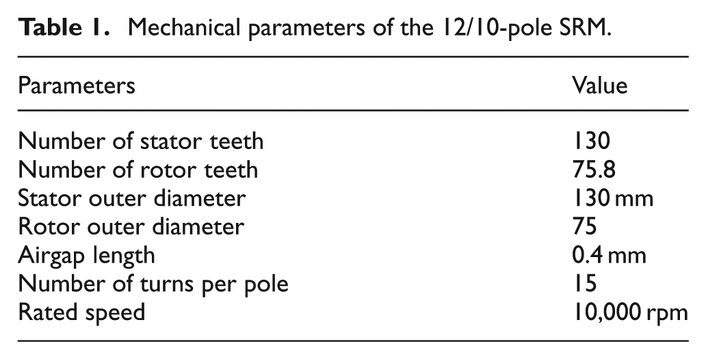
A six-phase SRM with 12-10 poles is designed for experiments. The basic parameters of the motor are shown in Table 1, and the physical motor can be seen in Figure 3. When the phase windings are connected according to the default positive and negative polarities, the winding arrangement is in a reverse series connection mode.
Mechanical parameters of the 12/10-pole SRM.

Motor stator and rotor diagram: (a) stator and (b) rotor.
Figure 4(a) depicts the magnetic vector diagram in NNN mode. When three phases are conducted simultaneously, the adjacent three poles have the same polarity, thus, each stator tooth must form a magnetic circuit loop with the corresponding stator teeth. Notably, the middle stator tooth can only form the magnetic flux through the rotor yoke, resulting in long magnetic circuit loops. As the motor rotates, the magnetic field’s direction and flux path change. With the increasing conduction current, the saturation level of the magnetic field in the entire stator yoke gradually increases.

The magnetic vector diagrams of the six-phase SRM when the current is 10 A: (a) NNN mode (b) NNS mode, and (c) NSN mode.
Taking phases A, B, and C as an example, the current is set as 10 A, when the stator teeth of phase B are aligned with the rotor teeth, the magnetic vector diagrams of the six-phase SRM with three kinds of magnetic pole polarities arrangements are shown in Figure 4.
Figure 4(b) shows the magnetic vector diagram in NNS mode. The stator poles polarities in phase B and phase C are NS, forming a magnetic circuit loop between these two teeth, which is a short magnetic circuit. This results in a higher magnetic flux density in the stator yoke between phases B and C. The stator poles’ polarities of the two adjacent teeth in phases A and B are the same, which can only form a magnetic circuit loop with the adjacent conducting phase, resulting in a long magnetic circuit. Therefore, the NNS mode involves both long and short magnetic circuits, with the short magnetic circuit having a higher flux density in the stator yoke. Taking phase B as an example, as the motor rotates, the magnetic field transitions from a short to a long magnetic circuit, causing the magnetic field direction to change during rotation. As the conduction current increases, the saturation level of the magnetic flux density in the stator yoke between teeth with the same pole polarity gradually increases.
Figure 4(c) shows the magnetic vector diagram in NSN mode. Since the stator poles’ polarities between two adjacent phases in the conducting three-phase system are different, a magnetic circuit loop is formed between adjacent stator teeth. At this time, the magnetic circuit loops are all short circuits, and the magnetic flux density on the stator yoke is relatively low. As the motor rotates, the direction of the magnetic field and the magnetic circuit mode do not change. With the increase of the conduction current, the saturation level of the stator yoke is relatively low, and the magnetic saturation occurs at the stator teeth.
Based on the preceding analysis, the magnetic flux distribution exhibits distinct patterns in different excitation modes. Under the NNN mode, both the stator and rotor yokes experience elevated magnetic flux density. In contrast, the NNS mode leads to high flux density primarily in the stator yoke located between stator teeth with NS pole polarity. Iron loss is related to frequency and average magnetic flux density. 28 Therefore, the iron loss is lowest in the NSN arrangement, highest in the NNN arrangement, and the NNS arrangement is in between.
In SRMs, the self-inductance can be expressed as:

where Nph and Rm are turn number per phase and the magnetic reluctance.
Figure 4(a) shows that the magnetic circuit paths formed between the stator teeth of phase B and the stator teeth of phase A and C are different in NNN mode, which means the magnetic reluctances are different in each magnetic circuit formed by different phases. In SRMs, each phase winding has the same turn number, from equation (1), the inductances of each phase are different. The inductance of three phases is shown in Figure 5.

Self-inductance under three magnetic pole arrangements (I = 40 A): (a) NNN mode (b) NNS mode, and (c) NSN mode.
Figure 5(a) shows the self-inductance in NNN mode, it can be seen that the self-inductance of phase A and phase C are approximately the same and greater than that of phase B. Figure 5(b) shows the self-inductance in NNS mode, where the self-inductance of phase A and phase B are approximately the same and slightly lower than that of phase C. Figure 5(c) shows the self-inductance in NSN mode, with the self-inductance shapes of the three phases being approximately the same.
The static torque characteristics in six-phase SRMs with three modes
Setting the SRM inductance as a linear inductance, the electromagnetic torque equation can be expressed as:

where
Equation (2) shows that when each phase winding is supplied with a constant current, the output torque of the SRM is related to the rate of change of inductance. Figure 5 shows that in the NNN mode, the self-inductance variation rates among the three phases differ significantly, resulting in different electromagnetic torques produced by the three-phase, which causes excessive torque pulsation in the system; in the NNS mode, the electromagnetic torque generated by phases A and B is lower than that of phase C, thus the system also experiences a problem of large pulsation; in the NSN mode, the inductance shapes of the three-phase windings are similar, so the electromagnetic torque produced by the system will be higher than that in the other two magnetic pole arrangements.
When the six-phase SRM runs at a conduction period angle of 180°, one rotor cycle can be divided into six conduction sequences. Therefore, the static torque under three-phase conduction is obtained through simulation, which further provides the synthesized static torque of the system. The resultant torque with different winding connection modes is shown in Figure 6, where Figure 6(a) and (b) represent the static torque when the three-phase winding conduction currents are 10 and 40 A, respectively. It can be observed that when the motor is saturated, the torque ripple in NNN and NNS mode is larger as the difference between phase inductance increases. The average torque is highest in NSN mode and lowest in NNN mode, with the output torque of the NNS mode falling between these two modes. Therefore, subsequent sections mainly analyze the winding configurations with NNS and NSN modes.

The resultant torque when the SRM runs in three modes: (a) resultant torque (I = 10 A) and (b) resultant torque (I = 40 A).
The winding topology and principle of variable polarity control
The winding topology in the six-phase SRM
Based on the analysis in part II, the phase inductance in six-phase SRMs with NNN mode is different between phases, leading to a reduction in torque. Therefore, the winding topologies for the other two modes are analyzed. The winding topology for the six-phase configuration is shown in Figure 7.

The winding topology in a six-phase SRM: (a) NS arrangement mode, (b) NSSN arrangement mode and (c) NNSS arrangement mode.
Figure 7(a) shows that the magnetic pole arrangement of any two stator teeth that are spatially opposite is NS polarity, and the poles polarities of the entire stator teeth are alternately arranged as NS. In a six-phase SRM, the number of stator teeth is an integer multiple of six. Consequently, an NS pole arrangement results in opposite magnetic polarities on stator teeth separated by 180°, indicating that the corresponding winding employs a reverse-series connection.
In Figure 7(b), the six adjacent stator teeth of the six-phase SRM are grouped, with each group having a polarity arrangement of NSNSNS (or SNSNSN), and this winding topology is defined as the NSSN arrangement mode. In this mode, each phase’s two stator teeth have opposite polarities, so the NSSN winding topology is a forward series connection. This causes the last stator tooth of the previous group and the first stator tooth of the next group to have the same polarity. For example, in a 12/10 pole SRM, the pole polarity of F1 and A2 is both with S polarity, leading to a six-step sequence where the three-phase conduction involves an NNS (or SNN) polarity arrangement. This results in the presence of short and long magnetic circuits, an asymmetric magnetic field distribution, and consequently larger torque ripple.
In Figure 7(c), the winding topology is defined as the NNSS arrangement mode. The polarity arrangement of four adjacent stator teeth is NNSS, which means the number of stator teeth must be an integer multiple of 12. Therefore, the NSSN winding topology is unsuitable for odd multiples of 6/5 pole combinations, such as 18/15 poles in six-phase SRMs. Under the NNSS arrangement, the magnetic pole polarity combination of any three conducting phases’ stator teeth is NNS (relative to the teeth being SSN).
When mutual inductance exists between phases, the magnetic linkage of each phase can be expressed as:

where
In the six-phase SRM, since more than two phases are excited simultaneously, it can be seen from equation (3) that the magnetic flux linkage of any phase is related to the self-inductance of the current phase and the mutual-inductance of the other phases. Taking phase A and B conducting simultaneously as an example, the magnetic pole arrangement between any two phases is an NS arrangement. The inductance of phase A under two-phase conduction is defined as LA-NS(AB), and the self-inductance of phase A when it is conducting alone is defined as LA-NS, and they are shown in Figure 8(a). It can be observed that under two-phase conduction, the shape of phase A’s inductance varies significantly, with the maximum inductance position delayed, and the rate of change of inductance increases, which is beneficial for the generation of electromagnetic torque.

Comparison of inductance under different excited models: (a) NS mode and (b) NNSS mode.
In NNSS arrangement mode, the magnetic pole arrangements of phases F, A and phases A, B are NS and NN arrangements, respectively, the inductances of phase A under the two conduction modes are shown in Figure 8(b), which indicates that the inductance of phase A under two-phase conduction does not change significantly compared to the self-inductance of phase A. Figure 8 demonstrates that the reverse series winding exhibits relatively severe inter-phase coupling, which reduces the independence between phases. When a system fault occurs, the system performance loss exceeds that of the forward series winding.
The principle of variable polarity control in the six-phase SRM
A comparative analysis of different pole arrangement modes in six-phase SRMs demonstrates that the NSN configuration exhibits higher output torque and lower torque ripple. However, examination of winding topology modes indicates that a forward-series connection cannot guarantee an NSN pole arrangement on the stator teeth under any three-phase simultaneous conduction condition. In SRMs, the polarity on the stator teeth is mainly related to the direction of current conduction. Taking phase A as an example, Figure 9 shows two magnetic pole polarity combinations for the forward series connection of the next phase winding. Comparing the two combinations in Figure 9, it is found that changing the current direction in the two stator windings A1 and A2 can alter the magnetic pole polarity of the corresponding stator teeth. By changing the current direction, the magnetic pole arrangement of the stator teeth for phases A and B, initially NNSS as shown in Figure 9(a), can be changed to SNNS as shown in Figure 9(b).

Polarity combinations of one-phase in forward connection: (a) NNSS combination and (b) SNNS combination.
The current waveform of a six-phase SRM with the winding topology arranged in NNSS arrangement mode is shown in Figure 10, which shows that when one phase conducts, the subsequent conducting phase has no circulating current. Taking phase F as an example, when phase F initially conducts, phase A has already finished circulating current, while phases B and C are in the circulating stage, and phases D and E are in the excitation stage. This means that when phase F is in the conduction angle, currents exist simultaneously in phases B to E. Assuming the winding topology is NSSN arrangement mode as shown in Figure 7(b), the magnetic poles polarities of adjacent stator teeth in phases B to F are NSNSN, and at this time, phase A is not conducting, which does not affect the magnetic pole definition of the other phases. When phase A initially conducts, if the current direction of phase A remains unchanged, the magnetic poles of the stator teeth adjacent to phases A and F will have the same polarity, making it impossible to maintain the stator teeth’s polarity in the NSN mode. Therefore, it is necessary to change the current direction of phase A to alter the magnetic pole polarity of phase A’s stator teeth, and this will ensure that the magnetic pole arrangement of any five phases with current always follows the NSNSN sequence.

Typical currents under unipolar control in six-phase SRMs (NNSS arrangement mode).
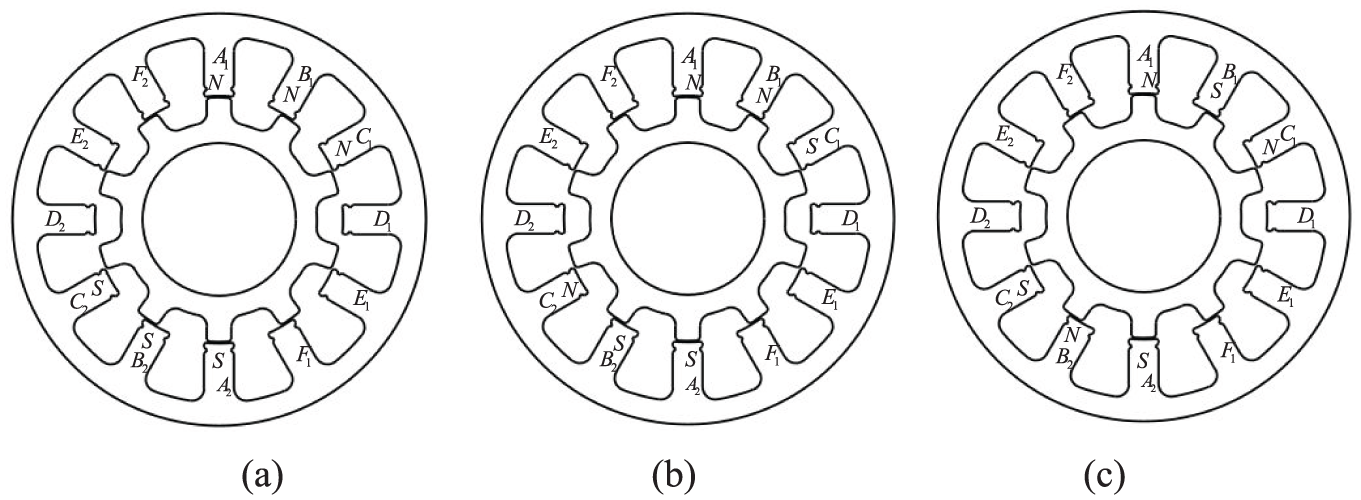
The phase sequence of a six-phase SRM is shown in part I, which operates in a half-cycle conduction mode with conduction at 0° and a conduction width is 180°. The six-phase SRM can be excited in six steps with three phases excited simultaneously, and these six steps can be expressed as: ABC→BCD→CDE→DEF→EFA→FAB. Therefore, the stator poles’ polarities arrangements are shown in Table 1. The stator poles’ polarities are represented in a clockwise order as shown in Figure 7(b), and the symbol ○ in Table 2 indicates that the phase is not conducting.
The control sequence in a six-phase SRM with bipolar control.
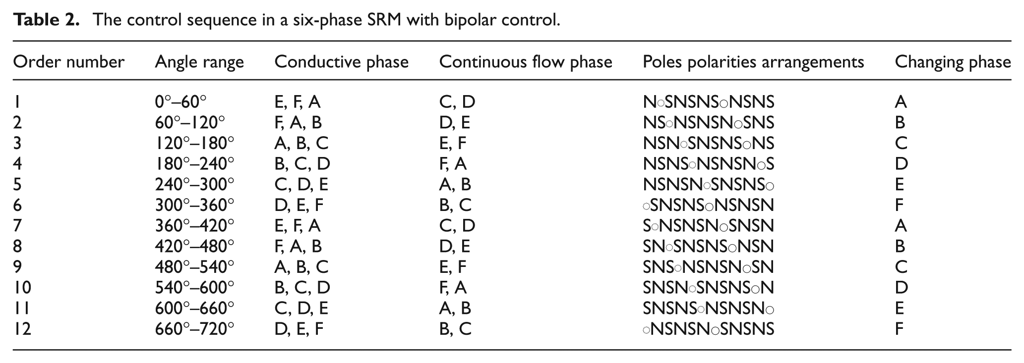
Table 2 details the sequence of magnetic pole polarities for the six-phase SRM under half-cycle conduction conditions. Although the conduction sequence involves six steps, the magnetic pole polarities can be arranged into 12 steps due to bipolar conduction. The 12 states are defined as numbered 1–12, with the state after 12 returning to state 1, forming a cycle as shown in Table 2. The six-phase SRM operates cyclically through these 12 states.
Taking the stator poles’ polarities of phase A as an example, in control state 1, phase A is conducting. Suppose the polarities of poles A1 and A2 are N and S, respectively. The remaining phases’ stator teeth are arranged in an alternating NS sequence, which can be determined accordingly. At this point, phase B is not conducting, and the winding is connected in NSSN arrangement mode. Therefore, whether the polarity of phase B’s stator teeth changes does not affect the motor’s magnetic circuit. In state 2, phase A is conducting, and phase B begins conducting. The polarity of phase A’s teeth remains unchanged. To maintain the magnetic pole arrangement with alternating NS polarities, the polarities of poles B1 and B2, must have polarities S and N, respectively. Compared to the B phase’s polarity in the state 12 (B phase conduction state), the polarities of B phase’s teeth change. Similarly, whenever a phase is conducted in the current state, its stator teeth’s polarities change compared to the previous cycle’s arrangement.
The above analysis shows that during the entire operation of the six-phase SRM, when one phase is conducting, the current direction of the winding can be changed through control methods, thereby altering the polarity of the stator magnetic poles in the phase which is about to be connected, and maintaining the poles polarities arrangement is NSN mode throughout the motor’s operation.
Simulation and experiment of the six-phase controlled with a variable polarity control strategy
Simulation of variable polarity control strategy under different winding topologies
According to the stator tooth poles arrangements illustrated in Figure 7, following the sequence from poles A1–F1 to A2–F2, the forward-series connection of phase windings yields magnetic pole polarity arrangements characterized as NSNSNSSNSNSN and NNSSNNSSNNSS, which are defined as NSSN and NNSS arrangement modes, respectively, as visually detailed in Figure 7(b) and (c).
The control method for the NSSN arrangement mode is formally specified in Table 2 which defines the 12 state sequence and the corresponding control actions for each phase namely positive or reverse current. To elucidate the practical implementation of this state machine Figure 11(a) provides a detailed temporal map of the conduction sequence. In this figure the progression of states from State 1 to State 12 as defined in Table 2 is aligned with the motors electrical cycle. The red and green lines explicitly indicate the instants where positive and reverse current controls are applied respectively thereby translating the tabular logic into an actionable control timeline. This illustration clarifies how the sequential state transitions in Table 2 are executed to maintain the desired pole arrangement in real time operation.

Phase sequence diagram with variable polarity control strategy: (a) NSSN arrangement mode and (b) NNSS arrangement mode.
For the NNSS arrangement mode, the control strategy implements a state-dependent polarity reversal mechanism: during state 1, phase E current undergoes active polarity reversal; in state 2, phase B requires reverse current control to maintain the alternating NS pole sequence; in state 3, phase C necessitates reverse control when pole B1 exhibits S polarity; in state 4, phase D avoids reverse control due to opposing polarities between poles C1 and D1; consequently, in state 5, phase E retains positive current based on preceding stator tooth polarity; and in state 6, phase F mandates reverse control. Analysis confirms that across two control cycles, phases E, B, and C undergo reverse control while the remaining phases sustain positive current, with this pattern reversing in the subsequent cycle. The complete conduction sequence is explicitly depicted in Figure 11(b).
When the six-phase SRM runs at the rated speed, with the same control angle and external power supply, the currents of six phases in the abovbe two arrangement modes are shown in Figure 12(a) to (b). Figure 12(c) presents the output torque for the three winding arrangement modes.

Simulations of current and torque in the six-phase SRM with different winding topologies: (a) currents in NSSN arrangement mode, (b) currents in NNSS arrangement mode and (c) torques in NSSN and NNSS arrangement mode.
In NSSN and NNSS arrangement modes, the variable polarity control strategies differ, leading to different directions of six-phase currents. This results in the magnetic poles’ polarities of stator teeth being arranged in an alternating NS pattern. Torque comparison shows that the output torque is the same in the six-phase SRM with different winding topologies.
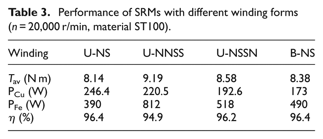
As shown in Table 3, at a speed of 2000 r/min, the U-NNSS winding produces the highest torque, but exhibits the highest core loss and relatively high copper loss, resulting in the lowest efficiency. The B-NS winding demonstrates the lowest copper loss and achieves the highest efficiency together with the U-NS winding, while the torque output of the U-NS winding is relatively low.
Performance of SRMs with different winding forms (n = 20,000 r/min, material ST100).
Fault-tolerant control strategy
During long-term operation of the SRM, there is a possibility of open-circuit faults and short-circuit faults. Taking open-circuit faults as an example, this section analyzes and compares the performance of motors with four winding configurations when a phase-loss fault occurs. During phase loss, the control conditions of each phase under normal operation remain unchanged; only the control circuits related to Phase A in the main power circuit are disconnected. At this point, the simulation waveforms of current under the four winding configurations are shown in Figure 13.

Currents in different winding connections with one-phase faults: (a) U-NS, (b) U-NNSS, (c) U-NSSN and (d) B-NS.
In Figure 13(a), the absence of Phase A results in the loss of mutual inductance between Phase A and Phase B, so during the excitation of Phase B, it is not affected by the current of Phase A, leading to a slower current rise rate compared with Phase F, and at this point, the current value of Phase F is higher than that of Phase B, and the shape at the current peak is no longer the same; in Figure 13(b), with Phase A missing, Phase A serves as a common tooth, so when the motor operates to the state where Phase F, Phase A, and Phase B are in three-phase simultaneous conduction, the stator yoke forms a short magnetic circuit, making the inter-phase currents approximately symmetric and smaller than the phase currents under normal operation, which in turn causes a decrease in motor torque; in Figure 13(c), when Phase A is absent, the magnetic pole arrangement of the remaining phases follows an NS alternating pattern, thus the magnetic pole arrangement of the U-NSSN topology is consistent with that of the B-NS topology in Figure 13(d), and the phase current shapes are approximately the same. Additionally, the simulation waveforms of electromagnetic torque for the four winding configurations under Phase A fault are shown in Figure 14, and the comparison between the torque under phase-loss fault and the normal torque is presented in Table 4.

Torque for different winding forms with one-phase failure.
Comparisons of normal and faulty torque for different winding forms (n = 20,000 r/min).

Experimental verification
The corresponding experiment platform is established, as shown in Figure 15. The torque sensor is JN338, and due to the accuracy limitations of the torque sensor, the comparison is made at a rotational speed of 1000 rpm. Data is collected using a data acquisition card, and the collected data is exported in Excel format. Therefore, the torque graphs presented later in this paper are based on the exported data.

Experimental test platform.
For convenience, when the SRM is controlled by conventional APC mode, three winding topologies which are shown in Figure 7, are named U-NS, U-NSSN, and U-NNSS, respectively. The SRM controlled with variable polarity control strategies is named B-NS. The current in the six-phase SRM with four modes are shown in Figure 16.

Currents in the six-phase SRM with different winding topologies: (a) currents in U-NS mode, (b) currents in U-NSSN mode, (c) currents in U-NNSS mode and (d) currents in B-NS mode.
Figure 16(a) shows that the current is distorted in U-NS mode, Figure 16(b) and (c) show that the currents are asymmetry. In B-NS mode, the currents are symmetrical. Torque of the SRM with four modes is shown in Figure 17, and the comparisons of torque are listed in Table 5.

Torque in the six-phase SRM with different winding topologies: (a) torque in U-NS mode, (b) torque in U-NSSN mode, (c) torque in U-NNSS mode and (d) torque in B-NS mode.
Comparisons of torque for different winding forms (n = 1000 r/min).

It can be seen from the Table 5 that, under the same bus voltage, the minimum output torque value of the B-US mode is higher than that of the other three forms. Its maximum value is close to the maximum values of the U-NSSN and U-NNSS winding forms. The B-US winding form has the highest average torque and symmetrical phase currents. The comparison results show that the motor with the B-US mode has higher output torque and the lowest torque ripple.
Under starting conditions, the current magnitude is determined by the current-carrying capacity of the conductors and equipment, which results in significantly higher current levels. After motor startup, the system requires rapid acceleration to the rated speed. During this process, the maximum operating current in the windings generally reaches 1.5 times the rated current, with the root mean square current set to 45 A. The control strategy remains Constant Current Control, and the simulation is configured with a rotational speed of 100 r/min. A dual-threshold current control method is adopted, with the upper and lower current limits set to 65 and 63 A, respectively. For bipolar excitation, the winding configuration follows the U-NSSN topology. During low-speed operation, the angular control strategy maintains a conduction angle of 0° with a conduction width of 180°. The performance comparison under these low-speed starting conditions is presented in Figure 18.

Torque waveforms under different winding forms at low-speed condition: (a) comparison of U-NS and B-NS, (b) comparison of U-NNSS and B-NS, and (c) comparison of U-NS and B-NS.
When the motor operates under the rated operating condition, the inductance value of the U-NS winding configuration is relatively small. This results in an excessively large current in the U-NS winding when connected to the same DC voltage. Therefore, the external power supply voltage for the U-NS winding is set to DC 230 V, while that for the other three winding configurations is set to DC 250 V. The angle control is uniformly set to 40° conduction with a conduction width of 160°. Figure 19 provides a performance analysis at the rated speed. In unipolar control, the external circuit is uniformly configured as an asymmetric bridge power converter; in bipolar control, an H-bridge power converter is adopted. The winding parameters and parameters of relevant control components are set to be consistent for the two external circuits.

Dynamic torque with different winding forms (n = 20,000 r/min).
Conclusion
This paper presents a novel variable polarity control strategy for six-phase switched reluctance motors. The strategy dynamically adjusts winding current direction to achieve an equivalent NSN pole arrangement while maintaining forward-series topology, thereby resolving the inherent conflict between high torque output and inter-phase decoupling. Experimental results demonstrate significant improvements in torque performance, ripple reduction, and fault tolerance. This work provides a universal design framework for multi-phase SRMs in high-reliability applications, transcending the limitations of conventional topological constraints. The core innovation lies in the optimized topological structure through intelligent polarity control mechanisms, achieving magnetic field optimization without sacrificing decoupling characteristics. As shown in experimental data, the torque waveform under the new control method is significantly smoother and more stable, with notable increase in average torque and substantial reduction in torque ripple. The variable polarity control paradigm established in this study has broad applicability, with its core value lying in breaking through traditional design limitations and providing advanced solutions for the development of high-reliability motor systems in multi-phase high-power application scenarios.
Footnotes
Handling Editor: Chenhui Liang
Funding
The authors received no financial support for the research, authorship, and/or publication of this article.
Declaration of conflicting interests
The authors declared no potential conflicts of interest with respect to the research, authorship, and/or publication of this article.