
Abstract
Switched reluctance motor (SRM) provide a potential candidate for electric vehicle (EV) applications due to rigid structure, potentially low production cost, the absence of permanent magnets, excellent power-speed characteristics, and high reliability and robustness. This paper aims to review the current research on the design, winding topologies, converter topologies, and control methods of switched reluctance motors (SRMs). Torque ripple and vibration are the main drawbacks of SRMs, which constrain their application. To conquer these drawbacks, multi-phase SRMs (MSRMs), optimum structure, and control methods of SRMs have been utilized over the past decades. In this paper, MSRMs with multiple combinations of stator/rotor poles and winding arrangements are investigated. Different converter topologies are compared, and a full-bridge converter is suitable for SRMs used in EVs. Torque sharing function, direct torque control, and direct instantaneous torque control are the main control methods to reduce the torque ripple of SRMs, which have been comprehensively summarized.
Introduction
Compared to fuel vehicles, electric vehicles (EVs) and hybrid electric vehicles (HEVs) can reduce the depletion of fossil fuels and global warming, and they are becoming more prevalent to replace traditional fuel vehicles.1–7 Electrical machines and drives play an important role in the development of EVs, the requirements of traction motor drives for EVs can be summarized as8–14
High torque density and power density
High torque for starting, low speed and hill-climbing, and high power for high-speed cruising
Wide speed range, with a constant power operating range of around 3–4 times the base speed
High efficiency over the wide speed and torque ranges, including low torque operation
Intermittent overload capability, typically twice the rated torque for short durations
High reliability and robustness appropriate to the vehicle environment
low acoustic noise
Acceptable cost
Since the permanent-magnet (PM) machines inherently own the merits of high torque/power density and efficiency due to the utilization of high-energy PM materials, they are widely used in hybrid vehicles and air conditioners.15–19 However, the cost of rare earth permanent magnets is still a problem for mass production. Moreover, the high-speed drive is limited due to the low mechanical strength.20–23 Therefore, there is increasing attention in rare-earth-free motors such as induction machines, synchronous reluctances machines, and switched reluctance machines.24–28
Switched reluctance motors (SRMs) are found to be much suitable for electric vehicle (EV) applications due to simple and rugged motor construction, low weight, potentially low production cost, easily cooling, excellent power-speed characteristics, high torque density and operating efficiency, and inherent fault tolerance.29–34 The literature gives evidence that the SRMs are competing with PM motors for electric vehicle propulsion applications, for example, SRM has been designed to compete with a PM motor for Toyota Prius vehicle.35,36 The SRM was designed as the same dimension of the PMSM used in the second-generation Toyota Prius with a 50 kW output power from 1200 to 6000 r/min in Chiba et al. 35 The SRM was designed as the same dimension of the PMSM used in the third-generation Toyota Prius with a 60 kW output power from 2768 to 13,900 r/min and 100 kW output power from 5400 to 13,900 r/min in Chiba and Kiyota, 36 and that means the shaft output can be enhanced by 160% in SRMs. However, high levels of torque pulsation and acoustic noise are still the major disadvantages of SRMs,37–39 especially in the EVs area due to the requirement of comfort. Hence, few EVs currently use SRMs, for example, Land Rover unveiled a range of seven electric research vehicles powered by an SRM and drive system developed at the 2013 Geneva Motor Show. The EVs are based on Land Rover’s 110 Defender model in which the standard diesel engine and gearbox have been replaced by a 70 kW switched reluctance motor. It is well-known that SRMs with higher phases generate reduced torque ripple and enhanced fault tolerance in comparison to three-phase SRMs.40–43 For example, the torque ripple in the three-phase SRMs is three times more than six-phase SRMs. Moreover, when one phase fault occurs, the output torque in six-phase SRMs is higher than that of three-phase SRMs.
This paper is an attempt to consider multi-phase SRM for automotive applications encompassing the gamut of issues such as design, modeling, winding arrangements, converter topologies, and control methods. In this paper, section 2 presents the topology, design, and comparison of multi-phase SRMs. Segment-type SRMs (SSRMs) are compared with conventional SRMs (CSRMs) with conventional windings. Section 3–5 concentrates on the winding topologies, converter topologies, and control methods of SRMs, respectively. Followed by the conclusions in Section 6.
Topologies, design, and comparison of multi-phase SRMs
Introduction of multi-phase SRMs
In SRMs, stator and rotor poles typically are symmetrical and evenly distributed around the circumference. In the conventional three-phase SRMs, the well-known stator/rotor poles combinations can be 6 stator poles and 4 rotor poles or 6 stator poles and 8 rotor poles, and these combinations are defined as 6/4 or 6/8 stator/rotor.44–46 Similarly to the three-phase SRM, when the phase number is bigger than three, the SRM can be defined as multi-phase SRM(MSRM), the structure of MSRMs are similar to three-phase SRMs, and phase number in conventional SRMs can be defined as

where ZS and ZR are the numbers of stator and rotor poles, and m is the phase number. Generally, the number of stator poles and rotor poles can be expressed as
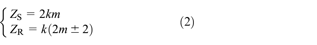
where k is the multiple of the basic combination of stator and rotor poles, for example, in four-phase SRMs, the combination of the stator and rotor poles can be 8/6 or 8/10, and when k = 2, the combination is 16/12 or 16/20. The combinations of the stator and rotor in different MSRMs are shown in Table 1.
Combinations of stator and rotor in MSRMs.

According to the phase numbers, SRMS can be divided into two kinds: even number phase and odd number phase SRMs.47,48 Taking three-phase and six-phase as the representative examples of the two kinds of SRMs, the arrangements of stator magnetic polarity in these two SRMs are shown in Figure 1. In odd number phase SRMs, such as three-phase SRMs, the arrangement of stator magnetic polarity usually is NSNSNS (define as NS mode), 49 and the magnetic field is symmetrical. In even number phase SRMS, such as six-phase SRMs, when the arrangement of stator magnetic polarity usually is NS mode, the magnetic field is unsymmetrical, and mutual inductance will be generated between phases, and that means the fault-tolerance will be reduced, a decoupled winding connection is needed in even number phase SRMs.50–52

The arrangement of (a) three-phase SRM and (b) six-phase SRM in NS mode.
In conventional SRMs (CSRMs), a position signal is needed to control each phase, hence, the need for position sensors increases following the increase of phase number. When the stator pole axis is aligned with the rotor pole axis, the position is defined as 180°, such as stator pole A1 in Figure 1(b); when the stator pole axis is aligned with the rotor slot axis, the position is defined as 0°, such as stator pole D1 in Figure 1(b). In Figure 1(b), it can be shown that the position signal of A1 and D1 are opposite, hence, the position signal of phase D can be obtained by the reversion of the position signal in phase A, which means that the number of position signal sensors for even phase motors is half of the phase number, while in odd number phase SRMs, the number of position signal sensors is equal to the phase number.
The design method of SRMs
SRMs run in the magnetic saturation region and phase current is nonsinusoidal, which makes the SRM become a multivariable and strongly coupled nonlinear system, and it is difficult to accurately calculate the relevant parameters of SRMs. The whole design process of switched reluctance motor can be divided into two parts, the first is the calculation of initial parameters and the second is the multi-objective optimization.
In the first part, the armature diameter Da and armature length la are given as 53

where Bδ is the magnetic load and its range is 0.29–0.92 Tesla, A is the electrical load, ki and km are peak current coefficient and square wave current coefficient, and all these four parameters are determined based on the designer’s experiences. Pem is the electromagnetic power which can be calculated from rated power PN and efficient η, n is the rated speed, and these two parameters are design parameters. Equation (3) is widely used in the initial design of SRMs.54,55
After the calculation of the main structural parameters of SRMs, the optimal design of SRMs is needed to seek the best parameters. However, due to the double salient poles structure of SRMs, the accurate model of SRMs is hard to establish. The analysis model mainly is achieved by the magnetic equivalent circuit56,57 or finite-element method (FEM).58,59 Due to assumptions and simplifications, the magnetic equivalent circuit is hard to establish an accurate model of the SRM. Compared with the magnetic equivalent circuit, FEM is more accurate and widely accepted, though it is time-consuming, and requires exact geometrical dimensions and material properties.
In the optimization function, the input parameters are multivariable, and the output values are multi-constrained, multi-objective, multi-extremum and nonlinear, hence, various intelligent algorithms are used in the optimization design of SRMs, such as genetic algorithm (GA),60–62 particle swarm optimization, 63 and differential evolution algorithm. 64 In Diao et al., 60 a belt-driven starter generator (BSG) is optimized based on the non-dominated sorting genetic algorithm-II (NSGA- II). The optimization flowchart is shown in Figure 2. The optimization function is established with average torque, ripple, and loss setting as optimization objectives. Compared with the initial parameters set, the average torque in the optimized motor is increased by 41.9%, and the ripple of the torque is reduced by 65.89%.

The flowchart of the NSGA-II.
Comparison of different multi-phase SRMs
The BSG motor investigated in Diao et al., 60 is compared with different multi-phase CSRMs. It is a kind of segmented-type SRM (SSRM). The structure of the SSRM is shown in Figure 3(a), another two kinds of four-phase SRMs with topologies of 8/6 and 8/10 are shown in Figure 3(b) and (c), and five-phase 10/8 and six-phase 12/10 SRMs are shown in Figure 3(d) and (e), all of these five SRMs are connected in conventional windings.

Machine topology of different MSRMs: (a) 16/10 SSRM, 60 (b) 8/6 SRM, (c) 8/10 SRM, (d) 10/8 SRM, and (e) 12/10 SRM.
The stator outer diameter and motor length are the same as the motor in Diao et al., 60 which are 128 and 80 mm respectively, the air gap is 0.25 mm in SSRM and 0.3 mm in other SRMs. The prototype in Diao et al. 60 does not show the best performance due to the constrained conditions, the motor was redesigned with the same slot fill factor and current density, and the other SRMs are designed under the same conditions. The main parameters and control angle of these six SRMs are shown in Table 2.
Parameters of different MSRMS.

The performance of these six SRMs are shown in Figure 4, the transient torque under the rated speed conditions is shown in Figure 4(a), and the relevant values of the torque, loss, and efficiency are shown in Figure 4(b). From the comparison of these six SRMs, it can be seen that the torque ripple is decreased with the increase of the phase number. The average torques in SRMs with the structure of 8/10 and 10/8 are the biggest, but the core loss in 8/10 is larger than the core loss in 10/8. The proposed structure in Diao et al. 60 with adjacent excited and auxiliary stator poles cannot produce larger torque, but it can reduce the core loss and improve the efficiency, and the fault tolerance is better than CSRMs. By comparing the torque, core loss and efficiency of these six SRMs, the performance of the five-phase SRM is better than the other SRMs.

Comparisons of (a) torque in rated speed and (b) values of torque, core loss, and efficiency.
Winding topologies
The operation principle of SRMs is that the magnetic flux is always closed along the path of maximum magnetic permeability to generate magnetic torque, and the flux distribution is associated with the winding connection, the arrangements of poles polarity and the number of excitation phases. Generally, there are three winding connection patterns, such as short-pitched CSRM (SCSRM),34,52,65–69 fully-pitched CSRM (FCSRM),70–77 and toroidal winding SRM (TSRM),78–81 take three-phase SRM as an example and three SRMs are shown in Figure 5.

Topologies of (a) SCSRM, (b) FCSRM, and (c) TSRM.
In three-phase SCSRM as shown in Figure 5(a), single-tooth coils are placed around the stator poles, while the rotor does not need any windings or magnets, which results in low manufacturing costs. Ignoring the mutual inductance between phases, the CSRM with short-pitched winding produces torque based on the rate of change of the self-inductance as shown as

where La, Lb, and Lc are the self-inductance of each phase, and that means the torque can be produced in the rising region or the falling region of the self-inductance.
The effect of the arrangements of poles polarity in three-phase SRM is analyzed in Zhan et al. 66 and two winding connections are proposed, which are named as the forward series connection and reverse series connection, and then different arrangements of poles polarity in four-phase SRM are analyzed in literatures.47,48 Based on the above analysis, it can be seen that the self-inductance in the forward series is greater than the one in the reverse series, and mutual inductance appears in series winding connections. A new winding configuration for a six-phase SRM is proposed in Widmer et al., 70 the six-phase SRM is driven by a conventional three-phase full-bridge converter, but the additional six diodes are necessary. The effects of the mutual-inductance on the torque and current in a six-phase SRM under different winding connections are indicated in Han et al. 50 Effect of winding connections on the performance of a six-phase SRM is given in Deng et al., 51 and the best choice for six-phase SRM is selected.
Figure 5(b) shows a three-phase SRM with fully-pitched winding, which has the same inner and outer diameter as the motor shown in Figure 5(a), each stator slot contains only one winding, and that means the utilization ratio of copper is higher than short-pitched winding. Ignoring magnetic saturation and fringe effect, when the stator pole arc and rotor pole arc are all equal, the overlap angle of stator poles and rotor poles is constant despite various rotor positions, and that means the self-inductances of phase windings are almost constant. In three-phase FCSRM, the torque is produced as

where Mab, Mbc, and Mca are the mutual-inductance between two phases. Based on the above analysis, it can be seen that two phases are needed to be excited simultaneously in FCSRMs.
The stator pole and rotor pole angle are set as 30° (mechanical angle), the ideal inductance of FCSRM can be shown as Figure 6(a), based on the inductance and equation (5), different conduction sequences are shown in Figure 6(b) to (d), which are named as unipolar 120°, bipolar 120°, and bipolar 180°.

Inductance and conduction sequences in FCSRM: (a) ideal inductance, (b) unipolar 120°, (c) bipolar 120°, and (d) bipolar 180°.
Mecrow et al.65,67,72 presented the concept of the fully-pitched winding and compared the SCSRM with FCSRM, but the conducted period of the SCSRM is one-third period, and it seems to be inaccurate for the usual conduction width is 160 electrical degrees. With the same stator and the current density, a three-phase SCSRM and FCSRM which is excited in bipolar 120° mode are compared in starting state and rated speed state. The torque curves are presented in Figure 7, and detailed results are tabulated in Table 3. When the SRM runs in starting state, the control strategy is current chopping control (CCC), and the phase current can be assumed as constant current. In SCSRM, the conducted sequence is AB-B-BC-C-CA-A, and the conducted sequence of FCSRM is AB-BC-CA, as presented in Figure 6.
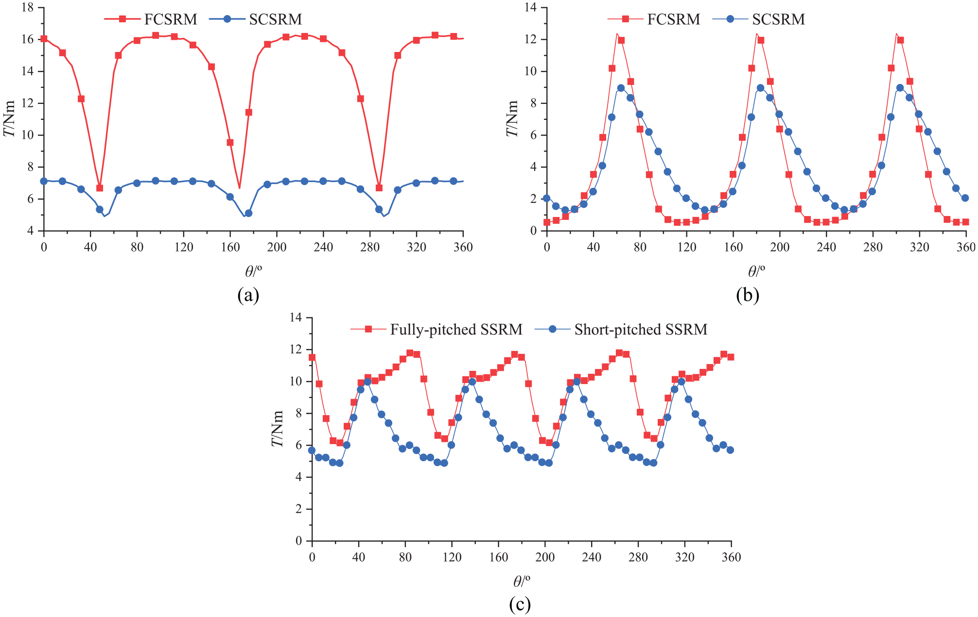
Comparison of short-pitched winding and fully-pitched winding. Three-phase SRM under (a) the starting state and (b) the rated speed state, and (c) four-phase SSRM under the rated speed state.
Comparison of SCSRM with FCSRM.

From Table 3, it can be seen that the performance in FCSRM is better than the performance in SCSRM in low-speed applications. When the SRM runs in high-speed applications, the torque which is produced in FPSRM is lower, for the time of current after-flow is longer and negative torque will be produced, and that means the fully-pitched winding machine is superior to the short-pitched winding machine in low-speed applications. In current literature, the fully-pitched winding is used in three-phase CSRMs, and this method is hardly used in multi-phase CSRMs since the mutual-inductance in the multi-phase CSRMs is complicated. There are three mutual-inductances in three-phase SRMs as shown in Figure 6, but the value is higher in multi-phase, for example, six mutual inductances between phases will appear in four-phase CSRMs. However, the fully-pitched winding is suitable for segment rotor SRMs, for the mutual inductance is only exist in the adjacent two-phase windings, for example, the fully-pitched winding is used in four-phase SSRM in Chen et al. 82 and six-phase-phase in Deng and Mecrow. 75 Comparison of four-phase segmented-type SRM (SSRM) with short-pitched winding and fully-pitched winding is shown in Figure 7(c) and the comparison values are presented in Table 3. It can be found that SSRM with fully-pitched winding can produce higher torque than the CSSRM.
The basic operation of toroidal winding SRM is examined by Yang et al., 80 Lee et al. 81 have presented a comparative study of conventional SRMs with conventional and toroidal windings. By the comparison, it is concluded that TSRM is suitable for SRMs to run at a high speed with a larger current and lower voltage. In Lee et al., 78 the converter topology 6-switch converter is proposed for the TSRM. It can be seen in Figure 5(c) that the threading technology must be used, consequently, the cost of winding will be increased significantly. Besides, the windings are wrapped around the yokes and half of the windings are outside the stators, and that will increase the volume of the motor.
Converter topologies
The power converter is a critical part of the SRM system, and its design is directly related to the performance and cost of the whole system.83,84 Since the 1980s, SRMs draw more and more attention, and a large number of researches on the topology of the main circuit are performed, an overall review of several kinds of power converters is presented in literatures.85,86
Asymmetric half-bridge converters
The typical converter for SRMs is the asymmetric half-bridge converter (AHB),41,87–90 and a four-phase AHB converter is shown in Figure 8(a). Taking phase A as an example, three operation modes are shown in Figure 8(b) to (d). From Figure 8, it can be seen that the converter operates with unidirectional currents, the upper and lower switched can be controlled independently, also the AHB converter offers higher phase independence. In AHB converter, each phase needs two switches and diodes, the number of these two devices is twice of the phase number, and it can only be realized using discrete components requiring power electronics devices, drivers, and protection circuits, and that means the circuit design is complex and implies a higher cost. To minimize the number of power devices, many other topologies are proposed, such as shared switch converter,91,92 split converter,93–96 C-dump97,98 energy storage converter, etc. Based on the converter topologies, novel topologies are proposed by adding didoes, inductance, and capacitor with optimized control methods. 84

(a) The asymmetric half-bridge converter for four-phase SRM, (b) magnetization mode, (c) freewheeling mode, and (d) demagnetization mode.
Share switched converters
Shared switch asymmetric half-bridge converters, also known as Miler converter, has been reported by Miller. 99 The (n + 1) switch converter for four-phase SRMs is shown in Figure 9(a). Compared with the AHB converter, in (n + 1) switch converter, a common bridge which is composed of common switch and diode is substituted for half of the bridges in the AHB converter. Three operation modes are shown in Figure 9(b) to (e). In low-speed applications, the performance of (n + 1) converter is the same as AHB converter, however, when the motor runs at high speed, the turn-on of the common switch during the magnetization period of the next phase interferes with the demagnetization of the previously conducting phase, and that will make the phase current cannot be freewheeled to zero, also the fault tolerance will be reduced. Furthermore, the current in the common switch and diode is the sum of the current in multi phases, and that means the current stress in the common switch and diode is higher than other devices.

(a) The (n + 1) converter for four-phase SRM, (b) magnetization mode, (c)–(d) freewheeling mode, and (e) demagnetization mode.
Split converters
A split converter used in a four-phase SRM is shown in Figure 10(a), and two operation modes are shown in Figure 10(b) to (c). From Figure 10, in this converter, only half of the DC voltage is used, and two capacitors are needed to stabilize the voltage in the middle point. A split-phase converter without capacitors is proposed in Corda and Skopljak, 94 however, the effects of removing capacitors on the performance of SRMs are not mentioned. Method of compensating midpoint voltage was proposed in Huang et al., 100 the performance of the motor is increased with the reduction of the fluctuation of midpoint voltage. In a split-phase converter, two phases must be conducted simultaneously at any time, so even a number of phase SRMs are required to take advantage of this converter. The main disadvantages of this converter are the effect of the floating of the midpoint voltage and poor fault tolerance.

(a) The split converter for four-phase SRM, (b) magnetization mode, and (c) demagnetization mode.
C-dump converters
The C-dump converter is capable of producing energy efficiency because the C-dump converter can demagnetize faster during the phase replacement process on the reluctance motor, energy after being discharged to the capacitor, directly used into the next phase and not returned to the DC source. The filter circuit composed of an inductor and capacitor is added to the converter, and the energy fed back to the power supply is reduced. A standard C-dump converter used in a four-phase SRM is shown in Figure 11(a), an inductor is required to form a buck chopper with the capacitor voltage which acts as the input voltage of the chopper, additional losses will appear due to the inductor used in the standard C-dump converter. Two topologies of the full-bridge converter for six-phase SRM are presented in Figure 11(b) and (c). A C-dump converter without inductors is proposed in Ardine and Riyadi. 101 In Kilic et al., 102 three additional diodes were added to a C-dump converter without inductors, and the fault tolerance of the system is improved. The main drawback of the C-dump converter is the need for an extra capacitor and the current stress of switches is high.

(a) C-dump converter for four-phase SRM and (b, c) full-bridge converter for six-phase SRM.
Integrated modular converter topology
Due to the three-phase full-bridge converter has become the standard solution and numerous manufactures offer the complete three-phase full-bridge converter power module, including the driver and protection circuits. Then, it is widely used in the three-phase AC motor drives as well as easy packings, such as the induction and brushless DC motor with the machine windings connected in delta or star. Hence, the drive cost was significantly reduced.
Integrated modular motor drive (IMMD) systems are proposed in Brown et al., 103 Wang et al., 104 converters are integrated into the motor, and based on this idea, an IIMMD five-phase SRM is proposed in Hennen et al., 105 winding outside of the SRM, and volume of the motor all are reduced. A three-phase full-bridge converter is used for a three-phase SRM with delta-connected windings in Clothier and Mecrow, 106 a six-phase SRM driven with a three-phase full-bridge converter is proposed in Widmer et al., 107 the windings are connected in star and delta connections and sinusoidal pulse width modulation (SPWM) control method is applied. Fully-pitched winding is introduced in the last section, and different conduction sequences are shown in Figure 6, it can be seen that bipolar current is needed in fully-pitched SRMs, fully bridge converter is used to realized bidirectional excitation control of SRM in literature.108–110 The complementary conducting phase windings in a four-phase SRM are reversely connected in series with diodes in Zhang et al., 110 and the SRM is realized by two single-phase full-bridge arms, however, a complex control method is needed and fault tolerance is reduced. In the hybrid electric vehicles (HEVs) area, a new converter is presented by integrating the converter, the motor with the charger in Song et al. 111 There are several operating modes for this converter to control the power flow. The topology which integrates one bridge of the inverter as a buck-boost converter and the other two bridges as a rectifier is proposed in Huseini et al., 112 and the cost of the system is reduced. Multilevel converters are proposed to improve motor performance by accelerating the excitation and demagnetization processes.109,113–116 For example, two three-phase full-bridge converters are connected to the windings in series in Sun et al., 109 so that it is more convenient to control the bidirectional currents in the windings. And the proposed drive system can provide an advanced fault-tolerance solution for both the open- and short-circuit faults in switching devices.
The comparisons between different converter topologies are shown in Table 4, Vdc and Id are the power supply and maximum current, D is the duty ratio in C-dump converter, Pcon is the conduction loss in one switch.
Comparison of different converter topologies.

Control methods for torque ripple reduction
In SRMs, reluctance torque is a nonlinear function of stator current and rotor position, compared with other types of motors, high torque ripple, and acoustic noise are the base drawbacks of SRM drives. The torque ripple should be kept minor because it excites mechanical oscillations in the drive train and induces fatigue on the shaft over time.117,118 This can produce noise that could be unpleasant to car passengers. 119 For decades, numerous solutions have been proposed to reduce torque ripple, vibration, and acoustic noise, methods can be divided into two types: optimizing the motor structure120–126 and optimizing control methods.117,127–136
In the method of optimizing the structure of the motor, the stator and rotor pole arcs are taken as design parameters and have been optimized in Li et al. 117 Research have been made to optimize the geometric shapes of the stator and rotor poles,122–124 these techniques do not require additional computing power and are effective for torque-ripple minimization within a limited operating range. However, the torque ripple has not been reduced enough to be able to use in applications requiring a silent operation, moreover, the maximum achievable torque is reduced due to the increased effective air gap.
The control parameters in SRMs contain turn-on angle, turn-off angle, limitation of phase current, and average voltage of DC bus, etc. The conventional control methods in SRMs contain current chopping control (CCC), angel position control (APC), and pulse width modulation (PWM). When SRMs run in starting status or lower speed, the back EMF is small and phase currents rise rapidly, CCC is used to limit the maximum of phase currents. While the SRMs run at high speed, the rising speed of phase current is slow, CCC does not work, and PWM control has little effect, the APC control method is often used to control the current waveform by changing the turn on or turn off angle. However, these three methods can’t solve the problem of high torque ripple fundamentally.
To reduce the torque ripple more efficiently, direct observation and control of torque should be developed and adopted. Mainly, there are two typical control methods for SRMs, indirect torque control and direct torque control (DTC).
Torque sharing function (TSF) is an effective indirect torque control method to achieve the control of torque ripple minimization in SRMs,137,138 and a typical block diagram of TSF is shown in Figure 12. TSFs distribute the required torque into adjacent phases, the given flux linkage can be obtained according to the distributed torque, and the torque ripple can be controlled indirectly by controlling the flux. TSFs can be offline117,127,128,135 or online.130,139 The offline TSFs are focused on optimizing the control parameters according to one or two secondary objectives. Several TSFs have been reported, such as linear, cubic, and exponential TSFs. 128 There is no reasonable difference between them using as sharing functions but any modification based on the motor characteristics can improve the performance. 135 The secondary objectives for the selection of TSFs include minimizing the copper loss and enhancing the torque-speed capability. 128 An offline TSF is proposed in Li et al., 117 which uses the flux linkage characteristics of the machine to create current reference profiles with low copper losses as secondary objectives. TSFs are tuned online by using estimated torque or speed feedback, and they require additional parameters. A four-phase 8/6 SRM with a rated power of 8 kW and a speed of 3000 r/min was controlled with CCC mode and TSF method in Wang et al., 140 result shows that peak to peak torque is 0.534 Nm in CCC mode, and 0.365 Nm in TSF method. One of the most drawbacks of the TSF method in industrial applications is the limitation of maximum speed with acceptable torque ripple, 139 and it’s difficult to convert distributed torque to current or flux setting.

Block diagram of TSF.
The block diagrams of DTC and DITC are presented in Figure 13. DTC was proposed by German scholar Depenbrock 141 and Japanese scholar Takahashi and Noguchi, 142 and it was first applied on SRMs in Cheok and Fukuda. 131 Based on flux linkage and torque double hysteresis loop, the flux magnitude and rotation speed of the flux linkage are controlled by selecting the appropriate voltage vector to achieve torque control. 143 A sensorless DTC method of a four-phase was proposed in Am et al., 144 a DTC method on a six-phase SRM driven by a six-phase AHB converter is proposed in Deng et al. 145 Variable switching frequency, current, and torque distortion may be the main disadvantages of the DTC hysteresis-based controller. 146 To reduce such problems, other methods are combined with DTC, such as space vector modulation (SVM) control, 146 RBF neural network, 147 etc. Another direct torque control method is direct instantaneous torque control (DITC), which was proposed in Inderka and De Doncker 148 by using a suitable commutation strategy according to the torque hysteresis and switching angle. In both of these methods, the torque output is controlled by a hysteresis controller with a pre-defined switching table.149,150 A comparison between DTC and DITC in a three-phase 12/8 SRM is made in Xu et al., 151 the torque ripple is 49% in DTC control and 30% in DITC control, experiment results shown that the DITC strategy maybe is a good choice for the practical engineering application rather than DTC, for the feedback torque and feedback flux are needed in DTC strategy, which increased the complexity of the control system.
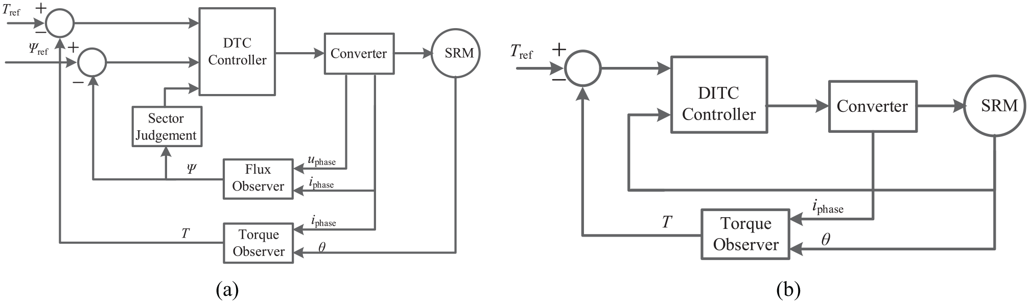
Block diagram of (a) DTC and (b) DITC.
Whatever DTC or DITC, the torque feedback is essential. The torque can be obtained directly by a torque measuring instrument, but this will make the system expensive and complex. Another method to obtain torque indirectly by measuring the information of voltage, current, and position. The most popular method is used the static T-i-θ characteristics to calculate torque, which is stored in 3-D lookup tables.
Conclusion
In this paper, a comprehensive review on the design, winding topologies, converter topologies, and control methods of switched reluctance motors (SRMs) has been presented. SRMs are found to be much suitable for electric vehicle applications, however, high levels of torque pulsation and acoustic noise made SRMs unsatisfied with the applications in EVs. Increased the phase number, optimizing structure and control methods can reduce the torque ripple of SRMs.
Multi-phase SRMs can be divided into even number and odd number phase SRMs, in odd number phase SRMs, the commonly used winding arrangement is that N and S poles are arranged alternately, which can be named as NS mode. While in even number phase SRMs, the mutual-inductance will be generated when the winding arrangement is NS mode, hence, a decoupled winding connection is needed in even number phase SRMs.
Numerous intelligent algorithms are used in the optimization design of SRMs, the most famous is the multi-objective optimizing design methods. Segment SRMs are proposed to increase the torque and fault tolerance, different multi-phase SSRMs and CSRMs are compared. From the comparison, it can be seen that SSRMs with conventional winding types cannot increase the torque, but they can increase the fault tolerance and reduce core loss. Multi-phase SSRMs with fully-pitched windings can increase the torque and reduce the core loss, torque ripple, and acoustic noise, which may be satisfied with the applications in EVs.
The power converter is a critical part of the SRM system, the usually used converter in SRMs is the AHB converter, however, the number of the power devices is increased following the increase of the phase number. Numerous converter topologies are proposed to reduce the power devices in multi-phase SRMs, by the comparison of converter topologies, the full-bridge converter may be the best choice for multi-phase SRMs for the three-phase full-bridge converter has become the standard solution and numerous manufactures offer the complete three-phase full-bridge converter power module, including the driver and protection circuits.
Optimizing control methods are used to reduce the torque ripple in SRMs, however, the most controlled motors are three-phase SRMs and these control methods are still in the research stage. Whatever in commutation control or torque estimation, the position signal is a critical part of the control in SRMs, the position encoder is usually used to obtain the position signal, which increases the cost of the system and reduces the fault tolerance. Sensorless control may be used to obtain the position signal without encoders, and the combination of sensorless control and torque control can overcome the existing problems in torque control methods.
Footnotes
Handling Editor: Chenhui Liang
Declaration of conflicting interests
The author(s) declared no potential conflicts of interest with respect to the research, authorship, and/or publication of this article.
Funding
The author(s) disclosed receipt of the following financial support for the research, authorship, and/or publication of this article: This work was supported in part by the Postgraduate Research & Practice Innovation Program of Jiangsu Province under Project KYCX20_3014, and in part by the State Scholarship Fund of China Scholarship Council under Grant 202008320572.