
Abstract
To address the increasing demand for miniaturization and integration in artificial satellites, the development of foldable and efficient deployable structures is crucial. This study presents a novel, intelligent variable structure that leverages NiTi shape memory alloy (SMA) to achieve an impressive deployable/foldable ratio exceeding eightfold. The structure’s extension and contraction can be precisely controlled through temperature regulation, providing significant adaptability. A key innovation of this design is the joint-driving mechanism, which uses multiple SMA corrugated plates to convert the material’s strain into rotational movement at the structure’s joints. Through optimization using the Optimal Latin Hypercube and Multi-Island Genetic Algorithm methods, the performance of a single SMA corrugated plate was significantly enhanced, resulting in improved torque output and rotation capability. Incorporating this optimized plate into the joint-driving mechanism enables the intelligent structure to achieve a maximum deployable/foldable ratio of 8.96 and a deployable angle of 20.62°. Furthermore, motion simulations allowed us to optimize the number of SMA corrugated plates, confirming the system’s ability to transmit significant deformation from the driving element to the entire structure. The numerical validation of this intelligent variable structure demonstrates its exceptional deployable/foldable ratio, highlighting its promising potential for various engineering applications.
Keywords
Highlights
This article introduces a novel intelligent variable structure actuated by NiTi SMA, achieving an over eightfold deployable/foldable ratio with precise folding control via temperature regulation.
An innovative joint-driving mechanism, incorporating SMA corrugated plates, effectively converts SMA strain into rotational motion at the structure’s joints.
The number of SMA corrugated plates in the joint-driving mechanism has been optimized, and the feasibility of transferring large-scale deformation to the entire structure has been validated through finite element analysis and motion simulation.
Introduction
Artificial satellites play a critical role in both space exploration and the advancement of various sectors of human society. According to the classification system proposed by the University of Surrey, satellites with a wet mass below 500 kg are categorized as small satellites, distinguished by their compact volume, low power consumption, and high functional density. Recent advancements in miniaturization and system integration technologies have significantly expanded the capabilities of small satellites, enabling them to perform functions previously reserved for larger platforms.1–3 Nevertheless, the process of satellite deployment remains resource-intensive, requiring considerable time, manpower, and financial investment.4,5 To mitigate these challenges, the adoption of deployable/foldable structures has become an effective strategy, allowing satellites to be compact during launch and subsequently deployed in orbit. 6
Extensive research efforts have been devoted to the deployable/foldable structures. Kitamura et al.7,8 proposed a longitudinal deployable/foldable arm utilizing triangular prism modules to meet the requirements of large deployable antennas and space platforms. In the United States, AEC-Able9,10 introduced the Folding Articulated Square Truss (FAST) and the Able Deployable Articulated Mast (ADAM), which utilize a quadrangular column as the primary modular unit. Similarly, Choi et al. 11 designed a quadrangular column-based extension arm to meet the high-precision requirements of space optical telescopes, while Russian researchers 12 developed quadrangular column-based deployable modules for the Mir space station. In these designs, elastic potential energy is typically stored in compression springs during folding and released during deployment to drive the extension mechanisms. Significant contributions have also been made domestically: Xu 13 realized sequential interlocking through a quadrangular column deployable/foldable arm; Gao et al. 14 proposed a triangular-column-based structure integrating longitudinal bars, beams, tension cables, and hinges; Han et al. 15 innovatively employed an unequal-length scissor mechanism to develop a scissor ring rib truss deployable antenna; and Yang et al. 16 introduced hyperelastic hinges in a triangular column deployable arm to improve energy storage and posture control. 17 Despite these advances, existing deployable/foldable structures still suffer from inherent limitations, such as low actuation accuracy, limited adaptability, and susceptibility to fatigue. These challenges have prompted the continuous exploration of new smart materials and mechanisms to further enhance their performance.
Recent research has increasingly focused on the application of smart materials, such as shape memory composites (SMCs) 18 and shape memory alloys (SMAs),19,20 to address some of these challenges. SMCs offer advantages such as low weight, high strength, and enhanced load-bearing capacity for spacecraft structures. 21 Concurrently, the emergence of intelligent variable structures inspired by origami concepts—such as photopolymerized, shape-programmable, and dielectric elastomer-driven origami—has further broadened the design space.22–24 Compared to other smart materials, SMAs (especially nickel-titanium alloys) exhibit superior actuation stress, larger recoverable strain, more accurate temperature control, and exceptional fatigue resistance, making them particularly well-suited for deployable/foldable structures requiring compactness, reliability, and high actuation efficiency. However, limitations in structural forms and actuation modes of NiTi SMAs still constrain their broader application in engineering practice.
To overcome these challenges, this study proposes an innovative intelligent variable structure characterized by a high deployable/foldable ratio. The structure comprises multiple deployable mechanisms, each driven by a novel joint integrating multiple NiTi SMA corrugated plates. A multi-objective, multi-parameter optimization of the SMA corrugated plates is performed to achieve optimal torque output and deployment angle. Based on the optimized parameters, the performance of a single deployable mechanism is simulated, determining the maximum achievable deployable/foldable angle and the required number of SMA corrugated plates under various loading conditions. Finite element analysis and motion simulations validate the superior performance of the proposed intelligent variable structure, demonstrating a high folding ratio, rapid deployment response, and precise temperature-based actuation control. This work presents a significant advancement in deployable space structure design by addressing the fundamental material and mechanical limitations inherent in current systems. The innovative integration of smart materials and structural optimization provides a new technical pathway for the development of lightweight, adaptive, and highly reliable deployable devices, thereby promoting the advancement of intelligent aerospace structural technologies.
Design of novel intelligent variable structure
Due to the limited strain capacity of SMA materials, exceeding the stress limit can result in material damage and hinder effective displacement recovery. To overcome this issue, this study introduces a novel ring structure that integrates NiTi alloy with aluminum alloy. This design aims to convert SMA strain into a relative rotation angle while ensuring that the strain remains within safe limits. This innovative approach generates the driving force required for the intelligent variable structure. The integrated cylinder, utilizing SMA corrugated plates, can be configured into a deployable/foldable mechanism in conjunction with the scissors structure. The scissors structure is well-known for its ability to achieve a large deployable/foldable ratio in composite structures and works in tandem with the relative rotation of the SMA integrated cylinder to drive the mechanism’s deployable/foldable movement. Figure S1(a) illustrates a typical scissors structure. To simplify the design and enhance calculation accuracy, the study constructs and analyzes a single scissors unit, as depicted in Figure S1(b). The SMA integrated cylinder is positioned at the center of two rods, each connected to the inner and outer rings, respectively. As the SMA begins to recover its shape, it induces a relative rotation of the rods, increasing the height on the opposite side of the rod as the rotation angle of the SMA integrated cylinder increases, thereby achieving the expansion effect.
In Figure 1(a), following the design and optimization process, a comprehensive structural model for the intelligent variable structure, based on the deployable/foldable unit, is presented. It is clear that the deployable/foldable ratio of the mechanism depends on the degree of torsion at the joint and the length of the rod. Longer rods and greater torsion result in a higher deployable/foldable ratio for the mechanism.
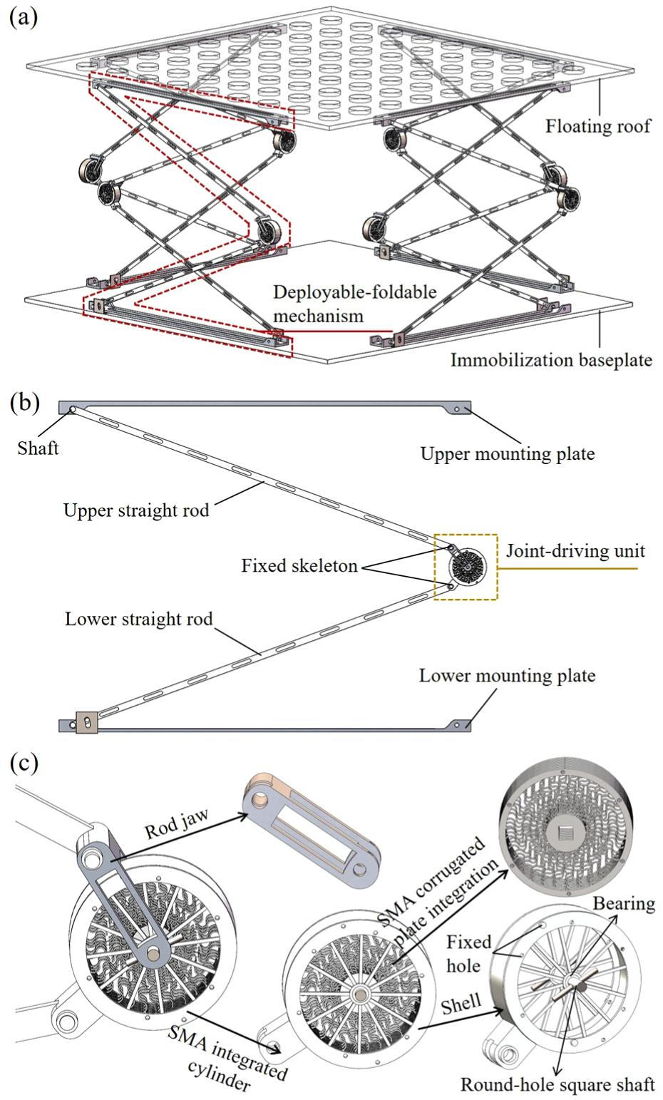
Structures design: (a) the intelligent variable structure, (b) single-group deployable/foldable mechanism, and (c) the joint-driving unit.
In Figure 1(b), the single-group deployable/foldable mechanism consists of an upper mounting plate, an upper straight rod, two fixed skeletons, a joint-driving unit, a lower straight rod, and a lower mounting plate. The upper end of the upper straight rod is attached to the upper mounting plate, allowing it to rotate around the fixed hole, while the lower end is securely fastened to the fixed skeleton with screws.
In Figure 1(c), the joint-driving unit includes a rod jaw and an SMA integrated cylinder. The SMA integrated cylinder primarily consists of a shell, SMA corrugated plates, bearings, and a round-hole square shaft. The SMA corrugated plate is positioned between the shell and the round-hole square shaft, with a bearing installed between the round-hole square shaft and the spoke.
Furthermore, to meet operational requirements, the intelligent variable structure can be configured with two, four, or eight groups of deployable/foldable mechanisms.
Figure 2 presents the operational principle of the intelligent variable structure. Initially, the structure remains in a folded state (Figure 2(a)), with an angle of θ1. An external motor then drives the round-hole square shaft in the joint-driving mechanism to rotate clockwise, causing the SMA corrugated plates to deform and the upper mounting plate to move upward. This sequence drives the structure into a deployable state (Figure 2(b)), characterized by an angular velocity w1 and angle θ2. When the motor stops, partial recovery of the SMA corrugated plates induces the structure to return partially to a folded state (Figure 2(c)), with angular velocity w2 and angle θ3. Finally, by heating the SMA corrugated plates to a temperature exceeding their phase transition point, the structure fully folds, as illustrated in Figure 2(d). In this final state, the structure exhibits an angular velocity w3 and an angle θ4, where w3 ≠ w2 ≠ w1 and θ4 = θ1.

Working principle of the intelligent variable structure: (a) initial foldable state, (b) motor drives the floating roof to stretch, (c) folding the floating roof after motor stops, and (d) SMA corrugated plate driven the floating roof folding.
In Figure 3(a), the SMA corrugated plate consists of fixed holes, an outer ring, corrugated rods, and an inner shaft. The outer ring is securely attached to the shell of the SMA integrated cylinder, while the inner shaft is firmly connected to the round-hole square shaft. During the deployment process, the inner shaft and outer ring rotate in opposite directions, inducing axial elongation of the corrugated rods, with negligible deformation in both the shaft and the ring. In the folding phase, the corrugated rods contract and return to their original lengths. As they undergo the highest strain during the deformation cycle, the corrugated rods are particularly susceptible to plastic deformation, which may compromise their shape recovery performance upon thermal activation. Given their critical role in the structural response, the corrugated rods are identified as the primary components for future design optimization. In Figure 3(b), the SMA corrugated plate is modeled using the SOLID185 grid type, with the following constraints: the outer ring is fixed, and the center mass point is set in the inner shaft with four-sided node coupling.

Structure design of SMA corrugated plate: (a) design and optimization parameters and (b) meshing and numerical calculation constraints.
Table 1 summarizes the key structural parameters of the intelligent variable structure and the SMA corrugated plate (with a length of l = 1000 mm). The parameters r3, r4, r5, and r6 are selected for multi-objective optimization. After finalizing the design of the intelligent variable structure, the torque and rotation angle depend on the number and material of the SMA corrugated plates embedded the SMA integrated cylinder. Therefore, it is crucial to perform finite element analysis and motion simulation on both the individual SMA corrugated plate and the complete deployable/foldable mechanism to evaluate their performance and interaction.
Parameters and size.

Materials and methods
A robust constitutive framework is indispensable for reliably predicting the coupled thermo-mechanical behavior of SMA corrugated plates. The ensuing sections briefly outline its experimental calibration and subsequent numerical implementation.
Constitutive model of SMA corrugated plates
The primary function of SMA corrugated plates is their shape memory effect, which is governed by a 3D thermomechanical model (SMA constitutive model) for stress-induced solid-phase transformations, as outlined in Auricchio and Petrini 25 :

The shape memory effect is characterized by seven constants (C1: hardening parameter; C2: phase-balance temperature; C3: elastic limit; C4: temperature scaling parameter; C5: maximum value of ||ε tr ||, where ε tr is the deviatoric transformation strain; C6: martensite modulus; C7: lode dependency parameter) that define the stress-strain behavior of the material during loading and unloading cycles under uniaxial stress-state and thermal loading conditions. To determine the constitutive model for NiTi SMA corrugated plates and specifically the values of C1 through C7, we conducted a series of tensile tests on NiTi SMA cylindrical rods using tensile testing equipment at the China Academy of Aerospace system and Innovation. As depicted in Figure 4, the results from the three tensile tests exhibit a high degree of consistency. Based on these experimental results and the SMA constitutive model from Auricchio and Petrini, 25 we determined the following material properties for the NiTi SMA corrugated plates: Poisson’s ratio was set to 0.30, the elastic modulus to 60 GPa, and the values of C1 through C7 to 400 MPa, 311 K, 140 MPa, 8.3 MPa/K, 0.07, 60 GPa, and 0, respectively.

NiTi SMA cylindrical rods tensile test.
Finite element analysis
Based on the material properties of NiTi SMA, a constitutive model for the SMA corrugated plate was developed using ANSYS Mechanical APDL. The finite element steady-state analysis proceeded through four stages: release, loading, unloading, and heating. The analysis accounted for large deformation effects and employed the asymmetric Newton-Raphson algorithm by setting NROPT to UNSYM. The constitutive model and boundary conditions were encapsulated in command scripts and executed in APDL. To ensure model accuracy, a grid independence test was performed. The SMA corrugated plate was modeled using hexahedral solid element grids, categorized into five different mesh densities: 19,203; 25,319; 31,993; 42,385; and 58,037. As shown in Figure 5, steady-state calculations were conducted for all five grid groups, divided into six steps: step 1: release; step 2: loading with a torque of 0.5 N·m; step 3: unloading; step 4: heating to the phase change temperature; step 5: heating to 330 K; step 6: maintaining the temperature at 330 K. Using the Y-component of rotation as the evaluation index, the differences in rotation at 10 s between the grid groups were calculated: y2–y1 = 0.01359 rad; y3–y2 = 0.01877 rad; y4–y3 = 0.00648 rad; y5–y4 = 0.00481 rad. Since the difference y4–y3 is significantly smaller than y3–y2 and y2–y1, the grid size of 31,993 was selected for further analysis.
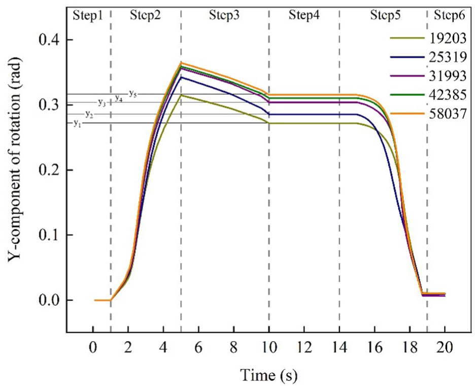
Mesh independence test.
Results and discussion
An integrated framework employing variable selection, surrogate modeling, and multi-objective optimization systematically refines SMA corrugated plate geometry to maximize thermo-mechanical performance.
Monolithic SMA corrugated plate structure optimization
Before initiating structural optimization, it is crucial to select an appropriate optimization method, as shown in Figure S2. The Optimal Latin Hypercube Sampling (OLHS) is an advanced extension of Latin Hypercube Sampling (LHS) designed to improve the spatial distribution of sample points and enhance space-filling performance. By employing optimization algorithms such as simulated annealing or genetic algorithms, OLHS maximizes the minimum distance between samples and ensures a more uniform distribution across the multidimensional space. This method is particularly well suited for high-dimensional design and optimization problems requiring efficient and representative sampling. The factors and levels involved in optimizing the SMA corrugated plate are detailed in Table 2. According to the optimal design empirical formula for the Optimal Latin Hypercube method, the entire parameter space can be effectively covered when the number of test combinations is >2(n + 1) (n + 2). To conserve computing resources, the number of optimized test groups has been selected as 84 (with n = 5), as shown in Table S1. The distribution of these 84 groups within the sampling space is illustrated in Figure S3. The sampling points for any three factors are evenly distributed, ensuring that the factor sampling is both reasonable and representative.
Optimization factor level values of SMA corrugated plate structural parameters.

To enhance the accuracy of multi-objective optimization design and mitigate the impact of varying numerical values of factors, the 84 groups of test combinations were normalized and individually calculated. The results for von Mises elastic strain (y1) and the Y-component of rotation (y2) were used as response variables, as detailed in Table S2. This study employed Isight software to perform multi-objective optimization and systematically analyze the individual effects of five design parameters on the response variables, as illustrated in Figure 6. Among these parameters, r4 has the most significant influence on y1. Extremely large or small values of r4 cause instability in the SMA corrugated plate, leading to a marked decline in performance. When r4 = 1.6251 mm, y1 reaches its minimum value. All five parameters exhibit a similar trend in their effect on y1: as the parameter value increases, y1 first decreases and then increases. For y2, r3 and r6 exert the greatest influence on amplitude, while r5 shows the least effect. As illustrated in Figure S4, factor r4 has the greatest impact on y1, accounting for 51.242% of its variation, while factor r6 has the most substantial influence on y2, contributing 46.62% of its variation. Based on the weighting relationships between the five factors and the response variables y1 and y2, simplified empirical models can be derived to represent the relative influence of the structural parameters (r3–r7) on the response variables y1 and y2.


Based on the distribution of 84 test results, a Kriging approximation model was employed to fit the response surfaces of y1 and y2, effectively capturing the interactions among multiple design parameters, as shown in Figures 7 and 8. For y1, the interaction between r3 and r4 shows the most significant effect: a large r4 combined with a small r3 leads to the poorest performance of the SMA corrugated plate, where y1 reaches 1.4%. Further analysis reveals that y1 attains its minimum when r3, r5, and r6 are large, while r4 and r7 are small. This indicates that the interaction effects between r3 and r5/r7, as well as between r4 and r5/r6, are comparable. Overall, strong pairwise interactions among the influencing factors generate multiple local extrema in y1, highlighting potential for performance optimization. In contrast, y2 reaches its maximum when r3, r5, r6, and r7 are large, and r4 is small. Comparable interaction patterns are observed between r4 and r7, r6 and r7, r3 and r6, r3 and r7, and r5 and r7. The most prominent interactions affecting y2 occur between r3 and r4, r4 and r7, and r6 and r7, resulting in multiple local optima. These results suggest that careful tuning of interacting factors is essential to achieving optimal performance in both y1 and y2.
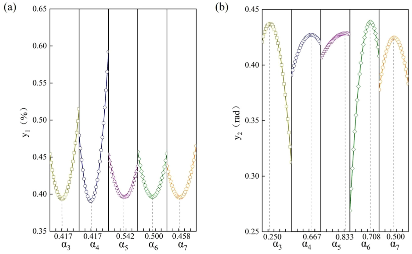
The main effects of structural parameters on the response value are compared: (a) the influence of different parameters on von Mises elastic strain and (b) the influence of different parameters on Y-component of rotation.

The interaction effect of different structural parameters on von Mises elastic strain: (a) parameters α3 and α4, (b) parameters α3 and α5, (c) parameters α3 and α6, (d) parameters α3 and α7, (e) parameters α4 and α5, (f) parameters α4 and α6, (g) parameters α4 and α7, (h) parameters α5 and α6, (i) parameters α5 and α7, (j) parameters α6 and α7.
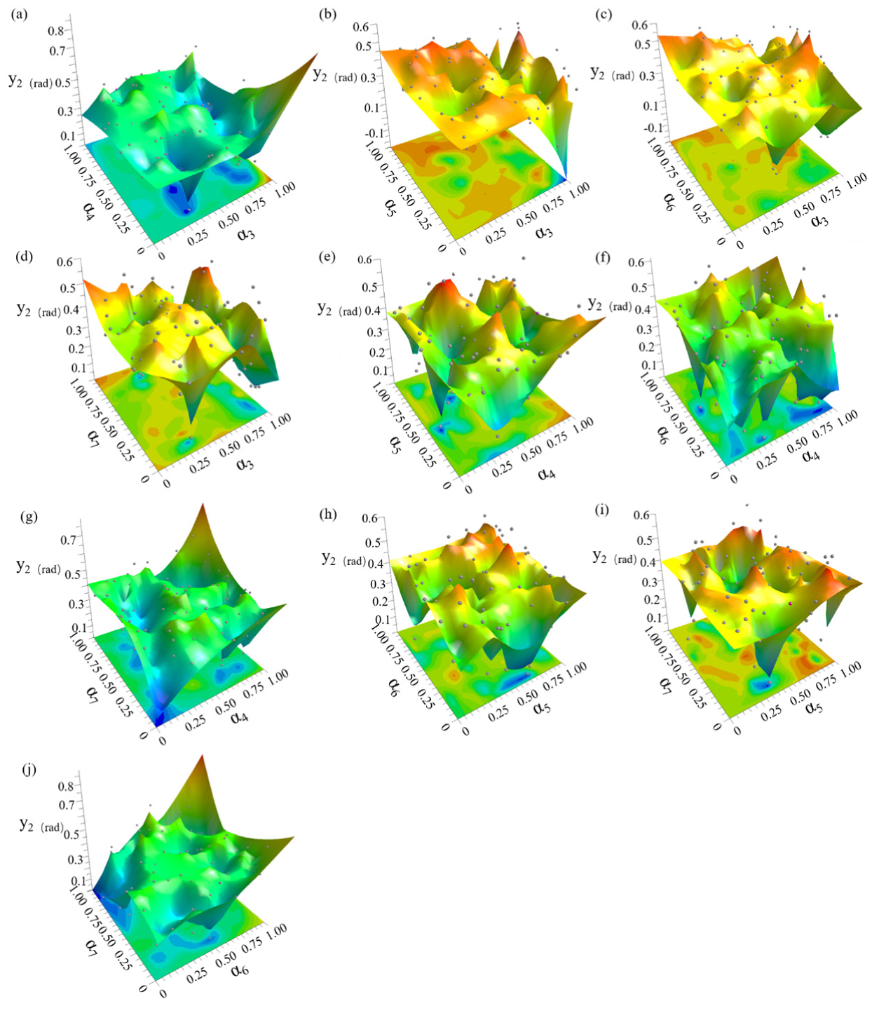
The interaction effect of different structural parameters on Y-component of rotation: (a) parameters α3 and α4, (b) parameters α3 and α5, (c) parameters α3 and α6, (d) parameters α3 and α7, (e) parameters α4 and α5, (f) parameters α4 and α6, (g) parameters α4 and α7, (h) parameters α5 and α6, (i) parameters α5 and α7, (j) parameters α6 and α7.
As detailed in Table 3, the Multi-Island Genetic Algorithm was applied to the 84 sample points and the constraints of y1 and y2 to develop training models for these response variables. The training model produced five randomly generated sets of factor combinations, as shown in Figure S5. The algorithm evolved over 20 generations, selecting the optimal individual in each cycle. All five factors reached convergence by the 18th generation. Table 3 presents the response values obtained after convergence. Numerical calculations were then performed on these five combinations. As shown in Figure 9, the simulated value of y1 exhibited a significant deviation from the predicted value, with a maximum error of 21.4%. In contrast, the predicted value of y2 closely matched the simulated result, with a maximum error of only 5.4%. The fourth group from the training results was selected as the optimal model, based on the median values of y1 and y2. Compared to the initial model, as illustrated in Figure S6, the corrugated rod configuration of the optimal model shows a gradual reduction in size from the outer ring toward the inner shaft.
Constraints for training the structural parameters of SMA corrugated plate.


The predicted values and simulated values of the five groups of response values were compared: (a) the response value is von Mises elastic strain and (b) the response value is Y-component of rotation.
Table S3 reveals that improper structural design causes two critical issues in the SMA corrugated plate. Group 73 shows minimal deformation of the plate, whereas Group 70 exhibits structural instability. As shown in Figures 10 and S7, compared to the initial model, the Y-component of rotation in the optimal model increases by 0.17 rad, whereas the von Mises elastic strain increases by only 0.01%. When the structure becomes unstable, the SMA corrugated plate cannot recover its deformation even after the load is removed, leading to overall structural damage. Moreover, a change of only 0.02 rad in the Y-component of rotation prevents the intelligent variable structure from performing the required deployment or folding.

Compare the Y-component of rotation of different SMA corrugated plate structures.
Monolithic SMA corrugated plate structure operating parameter optimization
To optimize the performance of the SMA corrugated plates, the study investigates the deformation characteristics of the optimal structure under various temperature gradients. As illustrated in Figure 11, Step 4’ involves three temperature gradient scenarios: (1) direct heating to 350 K (10–18 s) and maintaining at 350 K (18–20 s); (2) heating to the phase transition temperature of 311 K (10–14 s), then increasing to 350 K (14–19 s) and maintaining at 350 K (19–20 s); (3) heating to the phase change temperature of 311 K (10–14 s), then increasing to 330 K (14–17 s) and subsequently to 350 K (17–19 s), and maintaining at 350 K (19–20 s). Under the first scenario, the SMA corrugated plate exhibits incomplete deformation recovery. The phase transformation initiates during the second scenario. The third scenario leads to a faster deformation recovery, thereby enhancing the deployable and foldable functions of the intelligent variable structure.
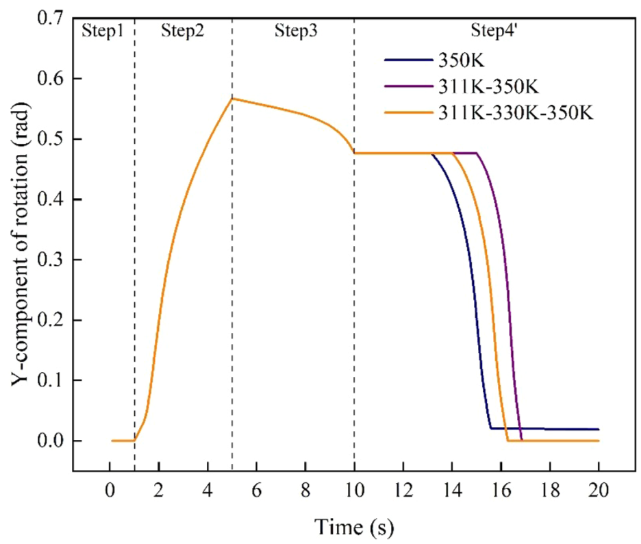
The effect of loading different recovery temperatures on the optimal SMA corrugated plate.
As illustrated in Figure 12, under the optimal temperature gradient, a moment load ranging from 0.6 to 1.0 N·m was applied to investigate the deformation behavior of SMA corrugated plates. The results indicate that increasing torque leads to a gradual rise in the Y-component of rotation, although the rate of increase progressively decreases. At a torque of 1.0 N·m, the SMA corrugated plate cannot recover its deformation following the heating process. However, at a torque of 0.95 N·m, the plate reaches its maximum Y-component of rotation (0.72 rad) without failure. Figure 13 highlights that the maximum deformation occurs at the interface between the corrugated rod and the inner shaft. As torque increases, the deformation of the square hole in the middle of the inner shaft also increases. When the torque reaches 0.95 N·m, the von Mises elastic strain is measured at 0.69%, allowing the SMA corrugated plate to fully recover.
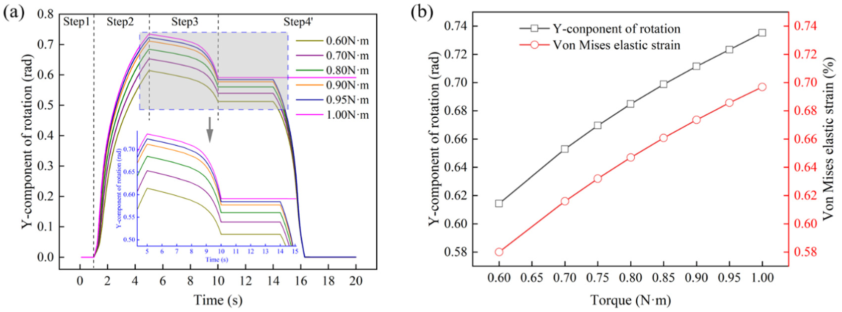
The influence of different torque values on the optimal SMA corrugated plate: (a) whole deformation process and (b) end time of loading stage.

The influence of different torques on von Mises elastic strain: (a) 0.6 N·m, (b) 0.7 N·m, (c) 0.8 N·m, (d) 0.9 N·m, (e) 0.95 N·m, and (f) 1.0 N·m.
Motion simulation of deployable/foldable mechanism
To validate the SMA structure under space-relevant conditions, a prototype of the SMA-based joint-driving mechanism was tested in a vacuum chamber at 1 × 10⁻⁴ Pa. The SMA element was resistively heated from room temperature to 100 °C, and its actuation was monitored in situ. As shown in Figure 14, the SMA-based joint-driving mechanism effectively transmits motion to the rocker arm, increasing its angle from 0° to 45°. No functional degradation was observed during the entire test, thereby demonstrating the feasibility and reliability of the proposed joint-driving mechanism in a high-vacuum environment.

Transition of the joint-driving mechanism from position A to position B after heating: (a) room temperature and (b) heating to 100 °C.
While the tests confirm the mechanism’s reliability under high-vacuum, several potential limitations warrant attention. First, fatigue effects are expected to be minimal due to low operational stress and a limited number of cycles (fewer than 10). Second, thermal cycling within the tested range showed no significant impact on structural performance. Third, two key failure modes have been identified: permanent plastic deformation occurs if pre-deformation strain exceeds ∼8%, though actual strains here remain well below this threshold; structural failure may result if applied torque causes stress beyond the SMA sheets’ strength limit. Together, these factors define critical operational boundaries and highlight areas for future investigation.
The rotation of the SMA integrated cylinder enables the intelligent variable structure to perform deployable and foldable motions. Determining the required number of SMA corrugated plates under specific working conditions involves calculating the output torque during cylinder operation and evaluating the rotation angle of the SMA corrugated plate under extreme conditions. For a more accurate comparison of the forces during the stretching process, a single-group deployable/foldable mechanism was selected for motion simulation analysis.
According to operational requirements, the intelligent variable structure is designed to support a maximum load of 20 kg. Therefore, each deployable/foldable mechanism group (G1, 5 kg) is configured to bear an additional 5 kg weight (G2). As shown in Figure 15, the initial height of the deployable/foldable mechanism is 56 mm, with an initial deployable/foldable angle (φ0) of 0°. The SMA corrugated plates achieves a maximum turning angle of 0.72 rad, corresponding to a deployable/foldable angle (φ1) of 20.62°. At this stage, the motor-driven mounting plate reaches a height of 502 mm, yielding in a maximum deployable/foldable ratio (η1) of 8.96 (H1/H0). Once the motor stops, the rotation angle of the SMA corrugated plate decreases to 0.13 rad. Consequently, the deployable/foldable angle (φ2) decreases to 16.90°, and the deployable/foldable ratio (η2) reduces 7.38 (H2/H0).
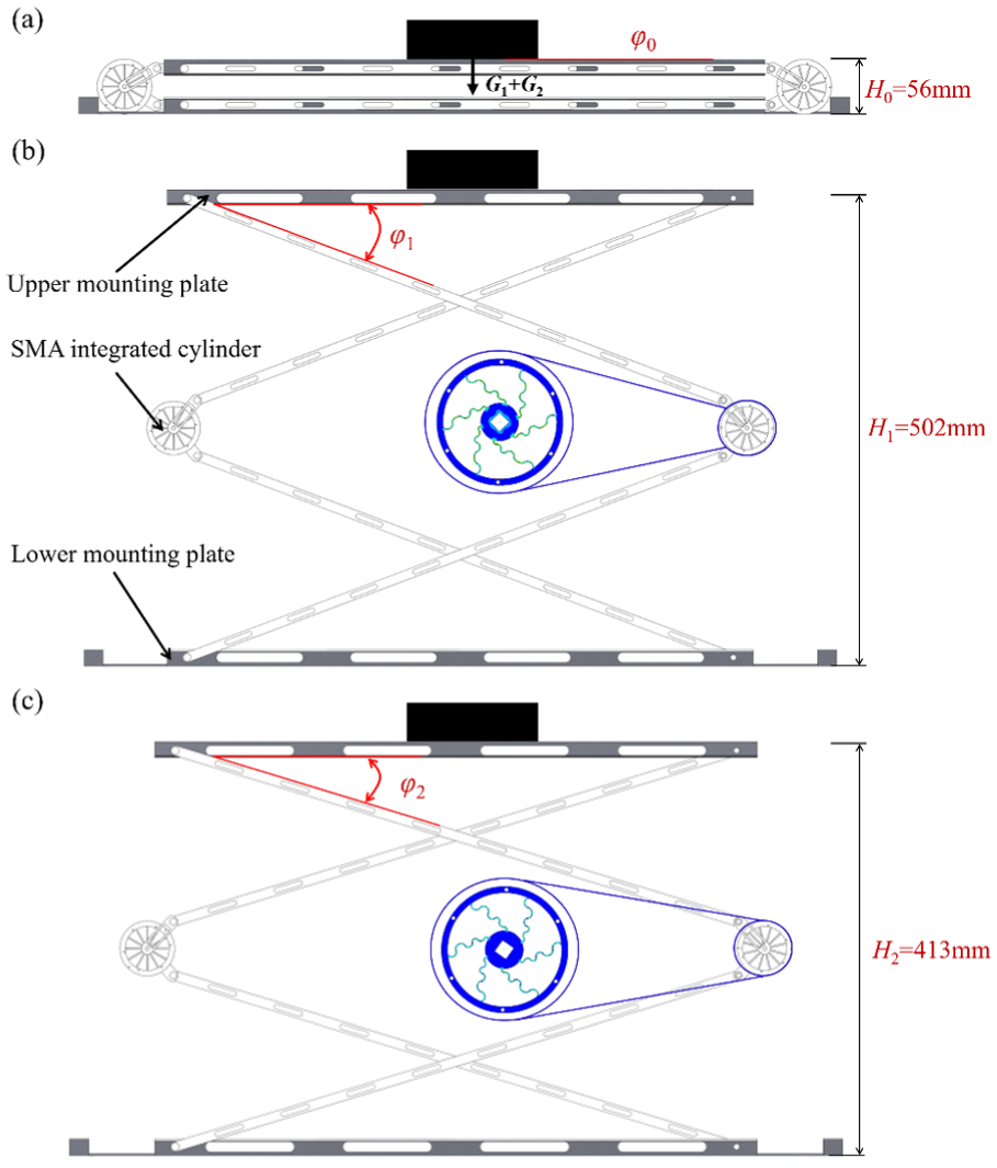
The working principle of the deployable/foldable mechanism to lift heavy objects: (a) initial state, (b) raise to highest position, (c) return to lowest position after unloading.
The SOLIDWORKS motion function was employed to conduct a motion simulation of the deployable/foldable mechanism as described. The simulation maintained a constant motor speed of 0.35 rpm and a lifting height of 502 mm to determine the torque required for the motor to drive the SMA integrated cylinder and raise the upper top plate to its maximum height over time. As illustrated in Figure 16, the driving torque gradually decreases as the upper top plate ascends. When lifting a 5 kg load, the SMA integrated cylinder requires a maximum torque of 29.28 N·m, which necessitating the use of at least 31 SMA corrugated plates. In contrast, when the mechanism extends without any additional load, the maximum required torque is 14.64 N·m, requiring a minimum of 16 SMA corrugated plates needed.

Comparison of the output torque of a single SMA integrated cylinder under different working conditions.
The performance of the SMA sheets under space conditions has been comprehensively evaluated. Thermal vacuum tests demonstrate that high-vacuum environments do not compromise their ability to undergo functional deformation. Given the structure’s low mass (∼10 g) and output torque on the order of newton-meters, the effect of microgravity is negligible in both the design and operational phases. Moreover, studies confirm that space radiation does not significantly degrade the material properties of the SMA or lead to undesirable emissions. Together, these findings confirm that the deployable/foldable mechanism can operate reliably and stably in space environments.
Conclusion
This study addresses the stringent requirements of satellite engineering by proposing a novel intelligent variable structure that leverages the unique properties of NiTi shape memory alloy (SMA). The design incorporates a deployable/foldable mechanism as its core component, enabling compact stowage and controlled deployment in space. To verify structural performance and feasibility, comprehensive finite element analyses (FEA) and kinematic simulations were conducted on both the monolithic SMA corrugated plate and the integrated deployable/foldable mechanism to validate the proposed design under expected loading conditions. The centerpiece of the structure is an innovative joint-driving mechanism composed of multiple SMA corrugated plates. These plates convert elastic strain into rotational motion at each joint, effectively scaling local actuation into global structural deployment. Through precise thermal activation, the SMA-driven mechanism achieves a deployable/foldable length ratio of ∼8.96:1, highlighting its compact-to-deployed dimensional advantage. For performance optimization, Optimal Latin Hypercube sampling was combined with a Multi-Island Genetic Algorithm to refine the SMA corrugated plate geometry. The optimized corrugated plate can withstand a peak torque of 0.95 N·m and produce a rotation of 0.72 rad per actuator. When integrated into the full mechanism, the design yields a maximum joint rotation of 20.62° under full-load conditions (requiring 31 plates) and attains the desired deployment performance with only 16 plates under no external load conditions. The integrated design and optimization method for an intelligent variable structure expands the application of smart materials in aerospace deployable/foldable mechanisms. Featuring a compact form and high deployable/foldable ratio, the resulting structure provides a practical solution for enhancing satellite deployment efficiency and promoting the development of next-generation space infrastructure.
Supplemental Material
sj-docx-1-ade-10.1177_16878132251395164 – Supplemental material for Design and simulation of an intelligent variable structure utilizing SMA corrugated plates
Supplemental material, sj-docx-1-ade-10.1177_16878132251395164 for Design and simulation of an intelligent variable structure utilizing SMA corrugated plates by Longda Zhou, Bingyang Li, Zongbao Chen, Jiangjie Jin, Meiqi Wu, Baorui Xu, Pengyu Lv, Xinyu Geng and Hongyuan Li in Advances in Mechanical Engineering
Footnotes
Handling Editor: Divyam Semwal
Funding
The authors disclosed receipt of the following financial support for the research, authorship, and/or publication of this article: This work was supported by the NSFC Excellence Research Group Program for “Multiscale Problems in Nonlinear Mechanics” (No. 12588201); the National Natural Science Foundation of China (NSFC) under Grant Nos. 12202010, 52441101, 12293001, U2141251, 52461045, and 52005494; the Beijing Nova Program (20240484719); the National Key R&D Program of China (2022YFC2806604); and the Laoshan Laboratory (LSKJ202200500).
Declaration of conflicting interests
The authors declared no potential conflicts of interest with respect to the research, authorship, and/or publication of this article.
Supplemental material
Supplemental material for this article is available online.
References
Supplementary Material
Please find the following supplemental material available below.
For Open Access articles published under a Creative Commons License, all supplemental material carries the same license as the article it is associated with.
For non-Open Access articles published, all supplemental material carries a non-exclusive license, and permission requests for re-use of supplemental material or any part of supplemental material shall be sent directly to the copyright owner as specified in the copyright notice associated with the article.