
Abstract
Increasing the thermal resistance of masonry wall systems is one of the effective ways to reduce energy consumption in the operation of masonry buildings. This increase is also demanded by newer, more stringent energy codes. However, the effective thermal resistance (R-value) of masonry walls is affected by many factors, such as thermal bridging, which occurs in places where highly conductive structural components penetrate insulating materials. Thermal bridging is common when connecting masonry veneers to structural backup walls. Furthermore, quick and precise methods for estimating the R-value are needed for thermal design improvements and code-compliance calculations. This study presents a comprehensive literature review on key factors that influence the overall thermal performance of masonry walls, methods to effectively estimate and measure R-values, and improvements in thermal design. In addition to identifying the main technical and practical challenges and the corresponding progress made on each front, key design considerations, such as code compliance, material properties, insulation types, and location, as well as special ties and shelf angles types, are also discussed. This study summarizes critical information and recommendations that will help improve the thermal design of masonry walls, hence reducing the energy consumption of buildings.
Introduction
Modern concrete blocks and masonry veneers are a significant constituent in the transition to sustainable buildings. Masonry buildings can be aesthetically pleasing, energy-efficient, and durable; moreover, masonry materials can be fully reused or recycled at the end of their service life, making them cradle-to-cradle building materials rather than cradle-to-grave ones (Earle et al., 2014). The initial production energy (i.e. embodied energy) of masonry buildings can be 30%–40% less than that of reinforced concrete buildings in similar sizes (Huberman and Pearlmutter, 2008). With the rapid change and higher standards of thermal requirements for building envelopes, masonry construction needs viable design improvements to meet stringent building energy codes as the minimum effective thermal resistance (R-value) has been increased over time. In the 2017 National Energy Code of Canada for Buildings (NECB, 2017), R-values have been increased by an average of 25% for some elements compared to its previous edition. This increase is expected to improve the overall energy performance of buildings by 10%–15% in comparison to previous versions of the code (NECB, 2011, 2015).
The thermal properties of materials are essential to the building’s thermal performance. Due to their significant thermal energy storage capacity (i.e. thermal mass), masonry buildings can often provide superior thermal performance compared to a light-frame building with similar thermal insulation values (ACI, 2002; Huberman and Pearlmutter, 2004, 2008). Aside from thermal mass, thermal conductivity also has a significant influence on thermal performance. Changing the shape and material of blocks and bricks can increase their thermal resistance; however, thermal insulation is still needed in masonry wall assemblies to significantly increase overall or effective thermal resistance. Therefore, the configurations of masonry wall assemblies also play a key role in the thermal performance of a wall. One of the challenges in the assembly configuration is thermal bridging. Thermal bridging occurs when highly conductive structural components penetrate the insulation plane (CCMP, 2013). Thermal bridging should be minimized in designs and carefully calculated as it is considered to be the main source of thermal performance deficiency in masonry walls.
Many regulations and guidelines have been established in recent decades to improve the thermal performance of building envelopes. The International Energy Conservation Code (IECC, 2012) provides and develops local codes for energy-efficient building design. Three significant changes to energy regulations and guidelines have been added to the most recent revision of the National Energy Code for Buildings of Canada (NECB, 2017). First, the overall thermal performance of the entire building envelope, rather than a single component, is considered in most regulations and guidelines. One type of thermal performance is the effective thermal resistance (R-value). The second change is the integration of much additional energy and thermal performance requirements, such as specific thermal properties of buildings, locations of different building elements, and the acceptable overall thermal performance for different climates. The third significant change is the calculation requirements for the effective R-value. The previous revisions of the NECB permitted the exclusion of major structural elements and other highly conductive elements that penetrate envelopes providing that they comprised less than 2% of the total wall area (Straube, 2017). The new code requires that all elements must be considered in the effective R-value calculation. Therefore, due to the newly included thermal bridges, the calculated effective R-value for many assemblies will be now smaller than previously determined. These significant changes require more accurate methods and tools to provide precise overallR-value estimates.
To comply with continuously evolving energy code requirements, the masonry and construction industries are developing new building techniques and are in search of an effective approach to calculate thermal resistance. Therefore, there is a need to review and improve the thermal resistance of masonry walls. Modeling also requires an accurate method for the estimation of R-values. To serve the aforementioned purposes, this paper provides a critical review of available literature on important factors that influence thermal performance, thermal design, and improvement of masonry walls. Numerical calculations, computer simulations, and experimental investigations on the evaluation of thermal resistance are presented and discussed.
Influence and improvement measures of different components
Typical components of concrete masonry walls are concrete blocks, mortar, grout, reinforcement (vertical, horizontal, and joint), insulation boards, shelf angles, veneer ties, and air gaps in the case of cavity walls. Figure 1 shows the main components discussed in this section. This section discusses each of these components and their effects on the overall thermal performance of masonry walls, according to previous experimental studies and from numerical simulations. Recommendations from previous studies to improve the thermal resistance of these wall components are also presented.
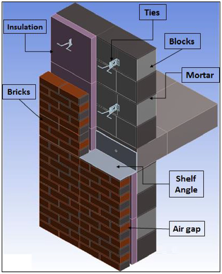
Components of the concrete masonry cavity walls.
Concrete blocks and clay bricks
The shape, size, aggregate size, moisture content, and density of block and brick units have a significant effect on the thermal resistance. Research has been conducted to optimize the blocks’ thermal design and obtain an accurate thermal resistance of different units. The thermal conductivity of concrete blocks or fired clay bricks mainly depends on the type of aggregate. For example, concrete thermal conductivity is generally correlated to concrete density (ESCSI, 2007). The type and shape of a hollow block can also have a large influence on the overall thermal performance. To enhance the thermal performance of masonry buildings, optimal thermal properties must be utilized correctly.
Voids in concrete blocks contribute significantly to the thermal resistance of masonry walls. The size, number, and distribution of a concrete block’s voids contribute significantly to the overall thermal efficiency of a block. The staggered holes elongate the heat flow path through walls which improves the blocks’ thermal resistance compared to aligned holes or solid blocks (Pierzchlewicz, 1996). Bai et al. (2017) experimentally demonstrated that a hollow shale block with many rows of holes can achieve a thermal transmittance of 0.726 W/(m2·K) (thermal resistance of 1.37 m2·K/W). After investigating the voids, studies were also conducted on web configurations. Bradfield and Szoke (1992) found that a smaller cross-sectional web area reduces the heat flow through wall assemblies. In addition, it was concluded that the smaller the intersection area between the web and the block’s face shell, the better the thermal resistance of a block. A 30% reduction was noticed in the thermal resistance of concrete blocks with two webs over the typical three webs concrete block (NCMA, 2012). Based on similar studies, some manufacturers have developed concrete masonry units with two webs, instead of three to reduce the thermal bridging effect. Although insulation inserts can increase a concrete masonry unit’s (CMU) thermal resistance, thermal bridging through solid webbing can reduce the effectiveness of the insulation (Kosny, 1995).
Lightweight aggregate with low thermal conductivity in lightweight concrete blocks can also reduce the thermal transmittance of blocks and bricks. With a large number of voids in the aggregate, lightweight aggregate concrete possesses a lower thermal conductivity and smaller density compared to normal concrete. Al-Jabri et al. (2005) experimentally compared the thermal conductivities of ordinary and lightweight hollow-core concrete blocks. Results showed that a 33% reduction of a block’s density caused a 60% decrease in the resulting thermal conductivity. Lightweight aggregates from waste materials, such as demolition wastes and agricultural residues, can be used to produce lightweight concrete blocks and achieve a lower thermal conductivity (Callejas et al., 2017). Agricultural solid waste from maize and corn has been incorporated with cementitious powder to prepare lightweight concrete (Wang et al., 2020). The National Concrete Masonry Association suggested that the thermal resistance of lightweight concrete blocks is less sensitive to the thickness of blocks compared to normal weight blocks (NCMA, 2013). A summary of the effects of concrete blocks on the overall R-value of masonry walls based on literature, along with recommendations to improve the thermal performance of masonry walls is presented in Table 7 (see Appendix).
Grout and mortar
Cement-based grout and mortar have been widely used in most modern masonry construction; three types of mortar are being used for historic masonry projects; lime mortars, hydraulic lime mortars, and Portland cement or masonry cement lime-based mortars. These types of mortar can differ significantly in their properties in both the plastic and hardened states especially in compressive strength, flexibility, water and vapor transmission rate, and frost durability. The appropriate type of mortar is chosen based on the environmental conditions and structural requirements (Suter et al., 2001). Grout is used to fill hollowed cores in CMUs to provide a bond between the CMU and steel reinforcements through cores. Mortar is a thick paste that acts as a binder between CMUs and provides a leveling bed for units, resulting in reduced stress concentrations.
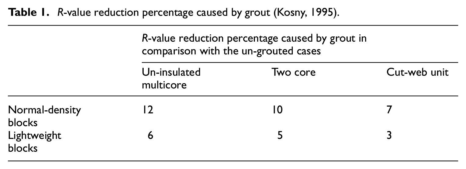
In general, grout reduces the overall R-value of a masonry wall. The grout effect depends mainly on the shape and thermal resistance of the concrete block. Kosny (1995) observed that local thermal bridges caused by grout-filled cores have a large influence on the R-value. Also, results showed that the reduction in overall R-value caused by grout decreases as the CMU thermal resistance increases. Figure 2 shows the shape of the units considered in the study and Table 1 shows the reduction percentage of the R-value in normal and lightweight grouted blocks compared to un-grouted (i.e. empty) blocks. It was concluded that cut-web units are less sensitive to the grout reduction effect.
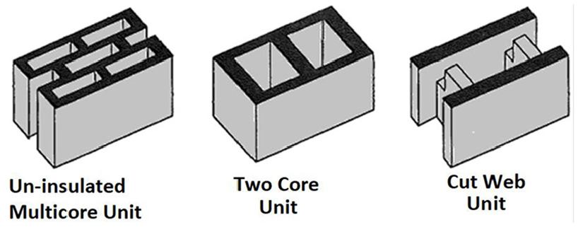
Shape of concrete masonry units.
R-value reduction percentage caused by grout (Kosny, 1995).
Mortar occupies only a small proportion (approximately 7%) of the total wall area in concrete masonry construction, but cause a significant reduction on a wall’s thermal resistance, depending on the thermal resistance of the concrete blocks. Kosny and Christian (2001) compared the effect of mortar on the thermal performance of masonry concrete walls in two cases: walls with insulated and un-insulated blocks. It was concluded that the mortar reduction effect on R-value increases as the thermal resistance of concrete block increases. The R-value reduction due to mortar in the case of walls made of insulated two core block was 12% more than the un-insulated two cores. In addition, the mortar reduction effect on a wall’s R-value is directly proportional to the thermal resistance value of a concrete block. Abdou and Murali (1994) experimentally proved the reduction effect was about 8% in a conventional wall. To decrease the amount of heat loss due to mortar, it was recommended that less conductive mortars be used or the area of mortar joints should be decreased. Another suggestion was to replace the side mortar with mechanical interlocking.
Zedan et al. (2016) conducted whole building simulations to study the thermal bridges primarily caused by mortar joints between insulated building blocks. Results showed that the effects of thermal bridges resulting from mortar joints is significant and may cause an increase in the annual heating or cooling load by 11%.
Ties and shelf angles
Veneer ties and shelf angles are used to hold brick veneers in place. They are typical repeating sources of thermal bridging. In the past, repeated thermal bridging sources were considered insignificant; however, as expectations for envelope performance rise, repeated thermal bridging sources have caught more attention. In recent studies, traditional steel masonry veneer ties and steel shelf angles are found among the largest sources of thermal bridging in masonry walls (CCMP, 2013; Roppel et al., 2012).
Research shows that tie material and shapes, and spacing can have a significant impact on the R-value of masonry veneer walls. Finch et al. (2013) showed that stainless steel ties with holes reduce the thermal resistance of exterior insulation over concrete/steel backup walls by 3%–9%, compared to 8%–25% for galvanized iron ties without holes. It was found that metal ties with a typical spacing between 400 and 600 mm, horizontally and vertically can contribute up to a 15% decrease in thermal resistance (Love, 2011).
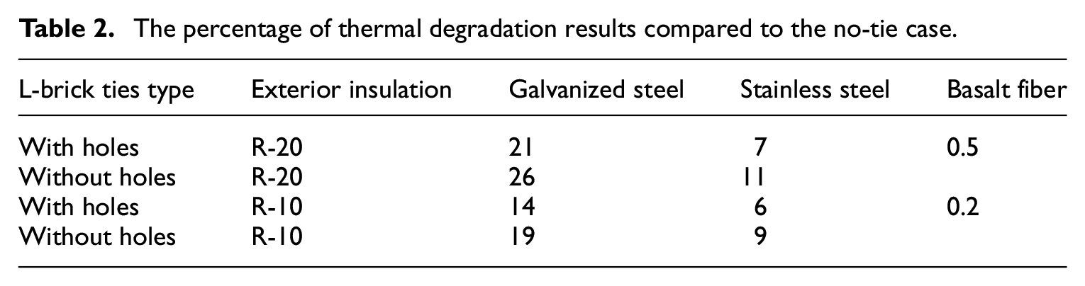
Finch et al. (2013), through numerical simulation, investigated the influence of different variables, such as tie material types and insulation levels, The variables addressed in this modeling were 2-inch × 16-gauge L-brick ties, with and without holes, made of galvanized steel and stainless steel and Basalt Fiber masonry cavity ties (proprietary UK product for a concrete backup wall). Table 2 shows the percentage of thermal degradation results compared to the no-tie case and using exterior insulation of R-20 and R-10 for all cases. The results concluded that as the exterior insulation R-value increases the thermal degradation effect of a tie on the overall R-value increases.
The percentage of thermal degradation results compared to the no-tie case.
The shape, size, material, and configuration of ties have been revolutionized to improve structural and thermal performance. Several tie shapes with different materials have been introduced to the market to minimize thermal bridging while meeting structural requirements (CCMP, 2013). Slotted ties (Figure 3(a)) can be fastened to the face shell of structural backing instead of being inserted in between blocks as traditional ties are typically used. Holes within the tie body are introduced to reduce the cross-sectional area, thus minimizing thermal conductance. Another type of tie is the block shear connector (Figure 3(b)), which has a horizontal embedment. This type of tie interlocks more effectively with blocks, helping to reduce the contact area (i.e. cross-sectional area), resulting in reduced thermal bridging.
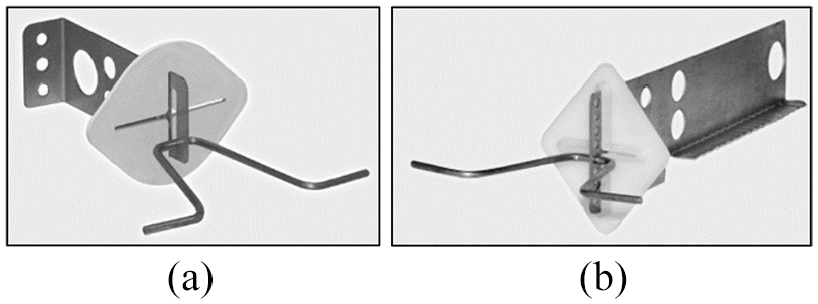
(a) Slotted ties and (b) block shear connector.
Shelf angles are anchored to structural backup using fasteners. Recently, intermittent structural support for shelf angles, which offset shelf angles from backing systems, such as knife plates (i.e. I-shape steel) and hollow structural section (HSS) tubes, are introduced to the market. Figure 4 shows the common shelf angle types. In this way, only intermittent supports penetrate the exterior insulation instead of shelf angles. The amount of insulation displaced by market-available intermittent supports is practically the same.
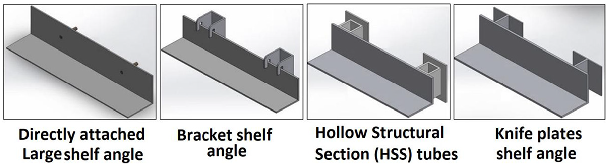
Common shelf angles types.
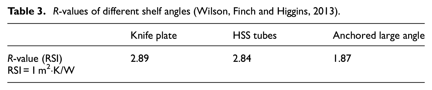
Finch et al. (2013) studied directly attached masonry shelf angles and concluded that these shelf angles have poor thermal resistance and reduce the R-value reductions by 40%–55% for typical exterior insulation thicknesses with stainless steel or galvanized ties. Shelf angles supported with intermittent knife plate or tubes resulted in much less reduction (12%–22%). Table 3 presents the influence of different shelf angle systems (namely knife plates, HSS tubes, and anchored large angles) on the R-value of a selected masonry wall (Finch et al. 2013). These studies confirmed that shelf angles supported on the outside of exterior insulation with intermittent supports result in less reduction in the R-value compared to the traditional approach (anchored large angles).
R-values of different shelf angles (Wilson, Finch and Higgins, 2013).
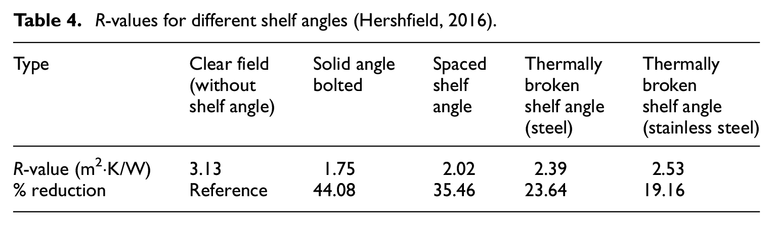
Another analysis on a wall assembly with shelf angles of different shapes and material properties was conducted using the data presented by Hershfield (2016). Table 4 presents the effect of different shelf angle systems on the R-value. The reduction in R-values ranges between 19% and 44% compared to the clear field’s R-value of 3.13 (m2·K)/W. “Clear field” is defined as planar areas with regularly spaced structural components that are free of windows, doors, and other irregularities (Barnes et al., 2013). This reduction range is based on the shelf angle shape and material used in each assembly. It was recommended that fabricating the entire angle out of stainless steel would minimize the performance impact of a shelf angle.
R-values for different shelf angles (Hershfield, 2016).
Another numerical and experimental study conducted by Di Placido et al. (2019) showed that shelf angle supported with intermittent brackets with perforations can decrease the overall R-value reduction by approximately 15% compared to the traditional directly attached large shelf angles.
Insulation for concrete masonry walls
Commercial and residential buildings have various energy codes enforced across the world. In North America, the two most pertinent energy codes are the International Energy Conservation Code (IECC) in the United States (IECC, 2012), and the National Energy Code for Buildings (NECB) in Canada (NECB, 2017). The reference energy standard that the majority of Canadian provinces use is ASHRAE Standard 90.1 (ASHRAE, 2019). While specific versions of these regulations are applied to different jurisdictions, each one must consider the effectiveness of the installed insulation. For example, cladding attachments can reduce the exterior insulation efficiency by 5%–10% for high-performance systems and 80% for poor systems (Finch and Higgins, 2017).
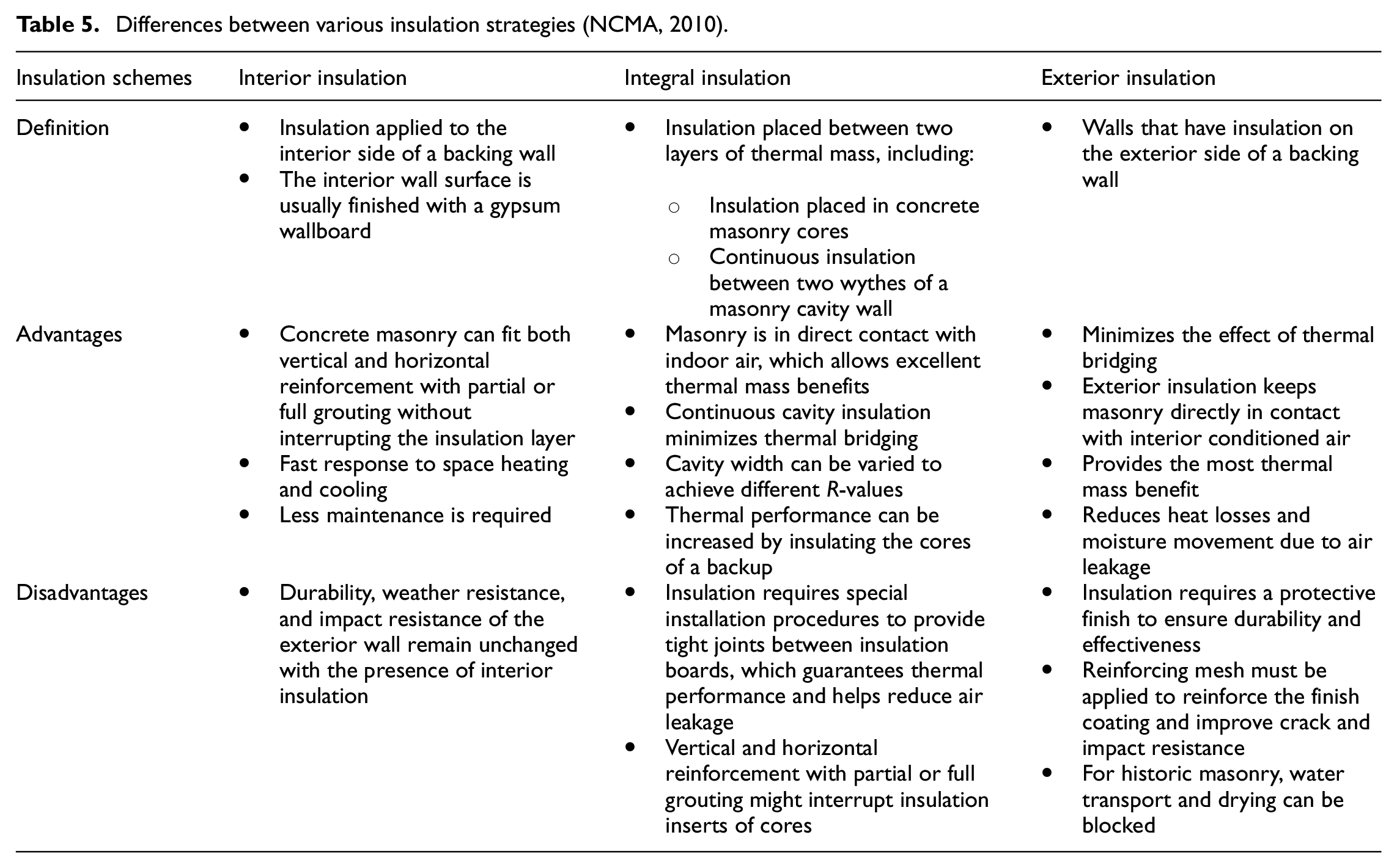
The thermal performance of any building envelope is highly dependent on its insulation design (Schumacher et al., 2013). Insulation designs depend on an economic trade-off between the present initial cost of improving the envelope and the future cumulative cost of operational energy for space conditioning while considering durability and maintenance costs. Different insulation designs have been used in masonry wall construction, depending on the required thermal properties, climate conditions, and feasibility of construction, cost, and other design criteria. Insulation schemes are divided into three categories based on the insulation locations: interior, integral, and exterior. Common integral insulation schemes consist of insulation block inserts placed inside a block’s cavities and granular fills in block core spaces. Exterior insulation systems completely cover all structural elements, such as columns and beams, to avoid thermal bridges and protect the structure from temperature variations (NCMA, 2013). Table 5 summarizes the differences between various insulation strategies based on the insulation location and the advantages and disadvantages of each insulation location.
Differences between various insulation strategies (NCMA, 2010).
Kosny (1995) investigated the thermal efficiency of integral insulation for the arrangements shown in Figure 5. The research found out that only the R-value difference between insulated and un-insulated blocks was only 20%–40% of the thermal resistance of the added insulation.
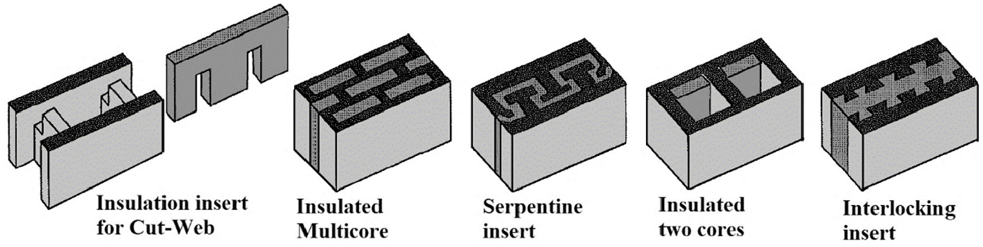
Arrangement of thermal insulation inside different block cavities.
McCall (1985) suggested that integral insulation with lightweight concrete blocks can increase the thermal efficiency value to 85%. Practical challenges in insulating masonry walls have been discussed by the European Insulation Manufacturers Association (Eurima, 2008). For exterior and interior wall insulation types, insulation boards should be in intimate contact with masonry to avoid air circulation from degrading the thermal resistance, and misalignments are mostly due to excess mortar between blocks and unclean wall surfaces. External insulation must be completely sealed at all perimeter edges to eliminate air infiltration between the panel and external wall. To address this issue, there should be a high level of construction quality control on-site.
Masonry veneer and air cavity
In modern construction, traditional thick, solid masonry walls have been replaced with thinner and more energy-efficient ones, such as masonry cavity walls made of a masonry veneer (typically brick) wythe, which acts as a rain screen, and a backup (concrete block) wythe with a layer of continuous thermal insulation. Thermal insulation is typically installed on the exterior surface of the backup, leaving an air cavity between the insulation and veneer. The main purpose of the air cavity for drying any moisture or draining water presented in the cavity and preventing liquid transmission by providing a capillary break. Ventilation in the cavity occurs by weeps in the brick veneer, which are required to connect the cavity with outdoor air. There are three common types of cavity walls: unventilated, pressure-equalized, and ventilated, as shown in Figure 6. Unventilated cavity walls were commonly used until the late 1900s; newer designs, such as the pressure-equalized cavity wall, emerged to reduce moisture accumulation in the cavity. Pressure-equalized cavities function by allowing air to enter the cavity, thus reducing or eliminating the positive force of wind-driven rain against the veneer. However, this type of cavity is not effective in creating a true net-zero pressure differential across a veneer (Conway, 2016) and the accumulated moisture and water were not able to be dried or drained sufficiently. As a result, a more effective type of cavity wall was introduced for moisture management: the ventilated cavity wall, allowing airflow in and out of a wall cavity through weep vents located at the top and bottom of the veneer panels.
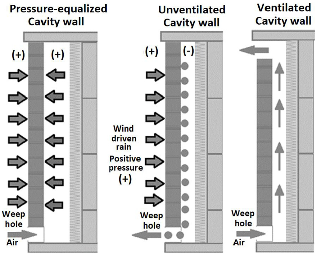
Types of cavity walls.
The air circulation inside the cavity can potentially reduce the insulating effect of the cavity. Recent revisions in the 2017 National Energy Code of Canada for Buildings (NECB, 2017) and 2015 National Building Code of Canada (NECB, 2015) state that: “materials installed toward the exterior of vented air space cannot be included in the calculation of effective thermal resistance of the assembly.” The contribution to the R-value of the wall from the air cavity and materials exterior to it is under on-going investigation. Stovall et al. (2004) found a temperature difference between cavity air and exterior for different air cavity configurations under different weather conditions. That means there is an insulating effect from the air cavity and brick veneer. Also, the ISO 6946 (ISO, 2017) shows the thermal resistance values for vertically vented air cavities (e.g. in the case of masonry cavity walls) increased from 0.11 to 0.17 m2·K/W as the air cavity thickness increased from 5 to 15 mm. The value remains at approximately 0.18 m2·K/W when the air cavity is between 25 and 100 mm.
Overall design considerations
Due to masonry walls’ durability, high thermal mass, and versatility to adapt to a wide variety of insulation schemes, there is a high potential for masonry to have an excellent thermal performance. Thus, it is meaningful to provide designers and analysts with design information regarding building types and energy conservation alternatives. This section presents the effective wall conditions that are recommended to be considered in innovative insulation schemes and block designs. The effects and consideration of significant design parameters will also be discussed.
Loading effect of cavity walls
The relation between structural loading and thermal performance of masonry walls is usually focused on subjecting masonry walls to extremely high temperatures (e.g. fire). Masonry tends to bend toward fire when subjected to high temperatures (Ono, 2007). Vertical loading tends to cause problems after a long period of fire exposure as the element tends to become laterally unstable due to high stresses produced by moments from lateral displacement (Rigão, 2012).
Numerical simulations were conducted by Nadjai et al. (2003) to address the influence of load application and wall slenderness on loading in fire conditions. The simulation results determined that the non-load bearing masonry wall showed displacements on both axes around the wall, and the maximum deformation occurred at the center of the sample, behaving as if it were fixed on four corners. For a load-bearing masonry wall, the displacements were smaller and restraint was only present at two sides of the wall: at the top and base of the masonry wall. It was concluded that loading has a direct effect on the displacement of masonry in fire conditions.
Another study presented by De Souza et al. (2019) identified the influence of loading on the fire behavior of masonry walls. Six masonries made of clay bricks laid with mortar were tested experimentally. These specimens were tested with and without loading of 10 t/m. The real-scale specimens were subjected to the standard ISO 834 (ISO, 1999) fire curve for 4 h. During the test, the properties of stability, airtightness, and thermal insulation were assessed. Results showed that loaded specimens yielded smaller deformations compared to unloaded ones. The load application resulted in a thermal insulation reduction of 23.8%, while the unloaded specimen showed a decrease of 43.3%.
Literature has shown few attempts to address the performance of load-bearing masonry walls with respect to high temperature as well as the relation between the structural and thermal performance of masonry walls. Further research is required as these attempts showed that loading has a direct effect on the displacement of masonry in fire conditions.
Contact resistance
Contact resistance effect can be significant on the overall R-value (ASHRAE, 2017; Hershfield, 2016; McGowan and Desjarlais, 1995). Guidance regarding the precise selection of reasonable contact resistance values between non-metal materials is not popular, although the contact resistance between metal materials is provided by ASHRAE Handbook Fundamentals 2017 (ASHRAE, 2017) and can range from 0.01 to 0.1 (m2·K)/W. Most of the currently available research data regarding contact resistances for buildings have been focused on light-gauge, steel-framed walls.
A study conducted by Hershfield (2016) showed comparable results between modeled and experimental testing when using a contact resistance of 0.002 m2·K/W at steel-to-steel connections and 0.010 m2·K/W at steel-to-concrete interfaces. These values were further confirmed by Di Placido et al. (2019). Their results also showed that contact resistances are significant, accounting for approximately 10% of the difference between modeled and experimental heat flow values.
Moisture accumulation
Moisture accumulation in masonry wall systems causes adverse health effects on occupants. Besides, moisture could cause physical and chemical damage to the building’s contents and reduces the efficiency of the buildings’ mechanical systems. Controlling moisture is required to protect both the occupants and buildings from the accumulated moisture effect and to reduce the maintenance cost. Buildings must be designed, constructed, and operated so that the materials manage to dry quickly in case they get wet (Xhexhi et al., 2020).
Moisture and water are often entrapped in the air cavity in cavity walls (see Section 2.5 for more information about the functions of the air cavity). Weep holes on the brick veneer are created for draining moisture from the air cavity to the exterior and for allowing airflow in the cavity to dry the moisture. Unfortunately, during construction, excess mortar falls into the air cavity behind the bricks causing the blocking of the weep holes with mortar (Schulenburg, 2000). To overcome weep plugging during construction, several devices and inventions have been developed (Koester, 2006; Schulenburg, 2000; Sourlis, 1993, 2000).
Variance of material properties due to temperature
In building designs and performance simulations, the thermal properties of materials (e.g. thermal conductivity, specific heat) of construction are often assumed to be invariant to temperature, moisture, and time. For example, the thermal conductivity of insulating material is often advertised using a single value that is implied to be constant. The value is usually obtained through laboratory tests according to standards, such as ASTM C518 (ASTM, 2015a), which shows the standard testing method for steady-state thermal transmission properties using a heat flow meter. Laboratory testing requires examining insulation materials under specific conditions, such as a mean temperature of 24°C with a temperature difference of 20°C using a one-dimensional heat flow meter. Research has shown that these testing conditions are not representative of realistic environmental conditions that insulation is typically subjected to Berardi (2017). Research has further shown that most insulating materials have an effective conductivity that may change over a range of environmental parameters (e.g. temperature, moisture levels, and material aging).
Many studies showed that the thermal conductivity of concrete at room temperature is in the range of 1.4 and 3.6 W/(m·K) and varies with temperature and moisture (Bažant et al., 1996; Harmathy and Allen, 1973; Kodur and Sultan, 2003; Lie and Kodur, 1996; Phan and Phan, 1996; Shin et al., 2002).
Measuring materials’ thermal properties is a challenge as there are few standardized methods available for measuring materials’ thermal properties. Overall concrete thermal conductivity decreases gradually with temperature and this decrease is dependent on the concrete mix properties (e.g. moisture content and permeability) and suggested to be as a result of the increment in pore volume in the cement-sand matrix and change in grain size due to the development of fracture planes within the coarse aggregates (Malik et al., 2020). Also, the variation of moisture content with an increase in temperature was suggested to be the main reason for this decreasing trend in concrete thermal conductivity (Bažant et al., 1996). Specific heat increases with an increase in temperature up to about 400°C and remains constant thereafter. Concrete consisting of blended cement with slag or fly ash and lightweight aggregates exhibit good thermal performance at elevated temperatures (Malik et al., 2020).
Insulation materials’ thermal properties are also dependent on temperature variations. Insulation materials made of inorganic fibers such as rock wool or fiberglass were tested experimentally. Linear temperature dependence of thermal conductivity has been noticed showing lower thermal conductivities at lower temperatures. However, foamed insulation materials like polyisocyanurate showed nonlinear temperature dependence with a significant deviation from linear behavior (Berardi et al., 2018).
Insulation and materials aging effect
More accurate simulations must be considered to monitor the change in insulation’s material properties through time and under cycles of different environmental conditions. Researches emphasize that the thermal behavior assessments must be carried out with accurate data about the materials, considering the environmental and aging effects on the thermal properties of materials.
Berardi (2019) and Belanger and Berardi (2018) have shown that the aging of the foams and the operating temperatures have higher impacts on the polyisocyanurates than on polyurethanes. Additionally, high moisture levels lead to lower performance in all foam materials, with open-cell foams experiencing the greatest thermal resistance reduction. Results showed that the effective resistance of closed-cell polyurethane and open-cell polyurethane was reduced by 15% and 18%, respectively when subjected to different environmental conditions (Belanger and Berardi, 2018). Also, it was concluded that the thermal conductivity of aged materials can increase by 100% from its pristine conditions, especially when polyisocyanurate foams are used in cold and humid conditions (Berardi, 2019).
Another study (Barnes et al., 2013) was performed on four different insulation materials (i.e. Dow Polystyrene, standard fiberglass, Aspen Aerogel, and Honeywell polyurethane) and these insulation materials were tested under controlled conditions to determine the effects of extended exposure to high temperatures and humidity on an insulation material’s performance. Samples were exposed to steady-state temperature and humidity conditions in an environmental chamber for 1 week and 1 month. For the steady-state test conditions, the temperature and humidity were set to 150°F (65.56°C) and 90%, respectively. Results showed that all four insulation materials experienced a reduction in R-value and thermal conductivity compared to the original samples. The R-value of the Dow Polystyrene and the standard fiberglass insulation materials were reduced by less than 3%, and there was no significant change between the 1-week and 1-month samples. The R-value of the Aspen Aerogel and the Honeywell polyurethane insulation materials were reduced by almost 10% and 25%, respectively. The Aspen Aerogel insulation degraded a further 3% between the 1-week and 1-month samples, while the Honeywell polyurethane insulation degradation remained constant. In addition to the reduction in thermal properties of the samples, minor physical changes to the specimens were observed. After conditioning, the Aspen Aerogel sample started to develop crystals on its surface, while the polyurethane samples began to bow and deform due to the exposure to high temperatures and humidity. The remaining two insulation materials showed no physical changes when exposed to high temperature and humidity for an extended period (Barnes et al., 2013).
Inaccurate assumptions about the thermal conductivity of materials cause inaccuracies in building performance. It affects design choices that will influence the thermal performance of the building. Designers should consider both the present and the future climate conditions to avoid misleading assumptions.
Energy efficient wall systems
The versatility of cavity walls to realize high-performance design requirements and insulation schemes has been discussed by Bradfield (2011). R-30 cavity wall can be designed by effectively arranging and selecting the correct insulation and by considering the wall tie analysis and its effect on thermal performance. Several studies have attempted to address energy efficiency, environmental effects in buildings, and building materials. Kumar et al. (2012) discussed the use of embodied energy and total energy in a sample room. This study focused on the comparison of two varieties of structures constructed using different types of bricks: clay brick and ash block structures. The ash blocks were manufactured using autoclaved aerated concrete material having 60% as the basic raw material, while other materials used are lime cement, gypsum, and aluminum powder. Due to millions of tiny pores, it has a low density and thermal conductivity. It was suggested that although ash blocks are more expensive than clay bricks, ash blocks can significantly decrease the size of air conditioning systems, energy usage, and total cost of building due to their lightweight and low thermal conductivity.
A comparative study between the thermal responses of conventional infilled frame construction and load-bearing masonry construction was performed by Abdou and Hamid (1993). This study addressed the thermal performance of load-bearing concrete masonry wall assemblies under hot, dry climatic conditions. The assemblies were modeled under dynamic thermal analysis using computer simulation. Results showed that concrete masonry walls provide several advantages due to the relative mass of masonry walls, result in a delayed migration as heat is absorbed. This event reduces peak heat flow and lowers the temperature differential, causing a slower response to outdoor temperature fluctuations and more stable indoor air temperatures. It was concluded that load-bearing concrete masonry walls are generally superior to conventional infilled reinforced concrete frames with brick masonry.
To improve the thermal performance of masonry walls, Su et al. (2019) developed a composite block that contains an inner hollow part, an outer solid part, and an extruded polystyrene layer sandwiched between the two components, as shown in Figure 7. This arrangement is consolidated by a set of tenon.
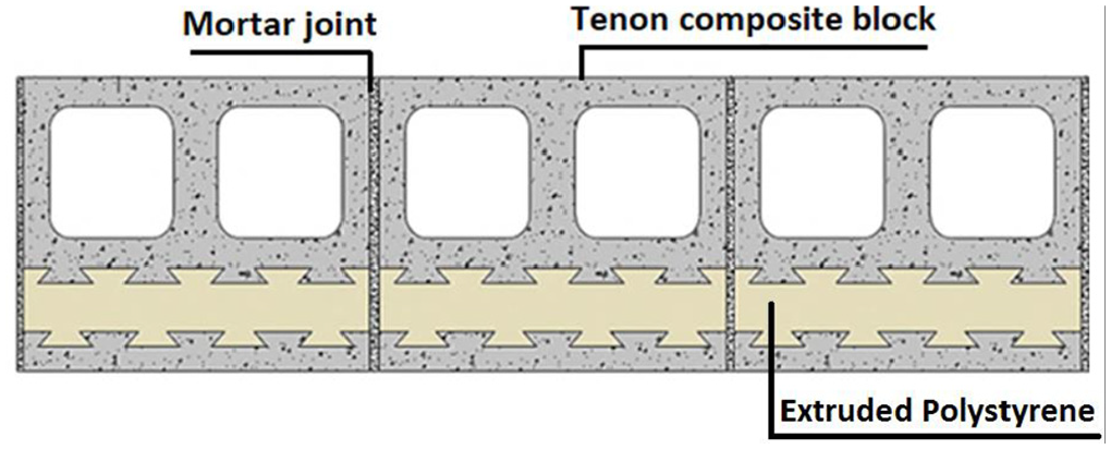
Horizontal schematic of a composite block wall (Su et al., 2019).
Different ratios of concrete mix were tested for the new composite. The mechanical strength and thermal properties of this innovative block (determined with experimental and numerical simulations) showed better performance compared to ordinary hollow core concrete blocks. However, the thermal bridge at block joints must be considered as well as the handling and transportation of the blocks are required to be addressed further.
Construction and design recommendations
One of the main goals in the construction industry is to reduce energy usage in buildings along with ensuring comfort. Advanced construction techniques and materials with superior thermal properties can be used to reduce thermal bridging in masonry walls. One common method to reduce the thermal bridging effect is the use of alternative steel or non-steel structural materials. Stainless steel is less conductive than normal steel and is highly encouraged to be used in the industry. Alternative materials, such as fiber-reinforced polymers (FRP) and thermal breaks, even though they are much less conductive, have issues common to new technologies. In many cases, a code-based acceptance procedure is not available for these new materials and alternative tests must be demonstrated and special approvals are required, which can cause reluctance when considering such details. Conventional construction and design approaches, as well as general recommendations for reducing thermal bridging, are as follows (Alshatshati et al., 2017; Barnes et al., 2013; D’Aloisio et al., 2012; Eurima, 2008)
Reduce the frequency of penetrations and eliminate continuous thermal bridges whenever possible.
Use structural elements with superior thermal resistance properties, such as FRP or stainless steel, which has an R-value three times greater than that of carbon steel.
Accommodate manufactured structural thermal break assemblies for use at structural steel elements and encourage using an insulating shim (such as FRP) between the shelf angle and concrete surface.
Insulation boards should be in intimate contact with masonry to avoid air circulation from degrading thermal resistance, and misalignments are mostly due to excess mortar between blocks and unclean wall surfaces.
External insulation must be completely sealed at all perimeter edges to eliminate air infiltration between the panel and external wall.
To avoid and control construction problems, there should be a high level of quality control and highly qualified technicians experienced in the construction industry working on site.
During the design phase and before construction, heat transfer modeling should be considered to analyze unusual conditions where thermal bridging may occur.
Develop strategies to minimize building energy loss due to thermal bridging before construction.
Evaluation of thermal resistance
Kosny and Christian (2001) showed that the thermal resistance of a wall can be overstated by up to 26.5% in construction details, such as corners and small thermal bridging items, are ignored. There is an increasing need for more accurate evaluations (prediction and testing) of the thermal performance of masonry walls and their elements as energy codes become stricter and performance simulation is becoming more prevalent. Thermal resistance is commonly used in the industry to describe the ability to resist heat flow. This section will discuss different approaches to evaluate the thermal resistance of masonry walls.
Simplified analytical approach
Thermal resistance of concrete masonry units
Two calculation techniques have been commonly used to determine thermal resistance: the parallel-path and series-parallel (e.g. isothermal-plane) methods. The parallel-path method is acceptable for calculating the thermal resistance of concrete masonry units (CMU), only if the units are not insulated (ACI, 2002). In this method, heat flow is assumed to be transferred through the CMUs in parallel flows. If the CMUs were hollow, the heat flow through the CMU (not including the mortar) would depend on the ratio between the web area and core area as shown in equation (1):

Where ac is the fractional core area; aw is the area percentage of the web; Rc is the thermal resistance of cores, empty or with fillings (m2·K/W); and Rw is the thermal resistance of concrete webs (m2·K/W). Note that the fractional area is the area of the studied element (core or webs) over the total area of the block.
The series-parallel method is applicable for both insulated and uninsulated masonry units and considers lateral heat flow in face shells (ACI, 2002; ASHRAE, 2019; NCMA, 2013). This calculation divides the block into a series of thermal layers. The overall R-value is the sum of the resistance of each layer. The equation is described as follows:

Where ac is the fractional core area; af is the fractional face shell area; am is the fractional mortar joint area; aw is the fractional web area; Ra is the thermal resistance of cavities between the veneer and backup wall, including continuous insulation (m2·K/W); Rc is the thermal resistance of cores, empty, or with fillings (m2·K/W); Rf is the thermal resistance of both face shells (m2·K/W); Ri is the thermal resistance of inside air surface films (m2·K/W); Rm is the thermal resistance of mortar joints (m2·K/W); RO is the thermal resistance of outside air surface films (m2·K/W); RT is the overall thermal resistance of a wall (m2·K/W); RV is the thermal resistance of veneers (m2·K/W); Rw is the thermal resistance of concrete webs (m2·K/W).
Applications of the series-parallel method for walls with configurations and materials were provided by the thermal catalog of concrete masonry assemblies (NCMA, 2012) and include fully grouted walls, walls with furring and gypsum, etc. For partially grouted walls, tables are available in National Concrete Masonry Association technical report number “TEK 06-02C” (NCMA, 2013) with R-values for walls of various grouting arrangements. The catalog has walls with different materials, such as perlite, vermiculite, polyurethane foamed-in-place, and others. It also presents values for blocks with different densities. The U-factor of a partially grouted single wythe wall without any thermal bridging elements (e.g. shelf angle, ties, fasteners, or slabs) can be calculated from the weighted-area average of the U-factors of the grouted area and un-grouted areas as follows:

Where agr is the fractional grouted area of the wall, aungr is the fractional un-grouted area of the wall, Ugr is the thermal transmittance of the fully grouted wall (W/m2·K), Uungr is the thermal transmittance of the un-grouted wall (W/m2·K), and R is the overall thermal resistance of a wall (m2·K/W). These tables can be used to calculate the grouted area and un-grouted area based on the vertical and horizontal grout spacing in partially grouted masonry walls. The thermal transmittance of the grouted wall (Ugr) and the un-grouted wall (Uungr) are provided in tables for various masonry units with different densities and core filling scenarios.
Area-weighted method
An exterior masonry wall consists of clear field and interface details. The clear field is defined as planar areas with regularly spaced structural components that are free of windows, doors, and other irregularities (Barnes et al., 2013). Clear field assemblies can contain thermal bridges from uniformly distributed secondary structural components, which are necessary to withstand loads. Examples of components included in clear field assemblies are brick ties, girts, or studs that support cladding. These thermal bridges do not include the ones related to intersections of the primary structure or between assemblies. The changes in construction or geometry that disrupt the uniformity of clear field assemblies are known as interface details. These details include slab edges, wall transitions, parapets, corners, and wall penetrations. Determining the impact of heat flow through clear field assemblies and interface details are necessary to accurately assess the thermal resistance of building envelope assemblies (ASHRAE, 2017). An area-weighted approach is commonly used to calculate the effective R-values at the interface details, where the proportion of area occupied by each intersecting element or clear field of a wall is multiplied by its thermal transmittance.
However, this approach has certain limitations as highly conductive building components can result in significant non-one-dimensional heat flow, or there may be other three-dimensional components that are not considered in basic parallel flow assumptions (Hydro, 2016). To increase the accuracy of the weighted average technique, instead of physical area, the thermal bridge influence area has been introduced, which is defined as the distance at which point heat flow through the assembly is no longer affected by thermal bridges. This method is more reliable and recommended when analyzing structures with low thermal conductive members such as some wood-frame configurations. However, its implementation is complex for common construction materials, such as concrete and steel (Hydro, 2016). The equation below illustrates the weighted-area method:

Where An is the area for the thermal anomaly (m2), Un is the thermal transmittance value for the thermal anomaly (W/m2·K), Ao is the area for the clear field (m2), Uo is the thermal transmittance value for the clear field (W/m2·K), and AT is the gross wall area (m2).
Due to different challenges in thermal behavior, various methods were introduced to determine accurate calculations of the general and overall R-value of masonry wall assemblies. Table A8 (see Appendix) summarizes all of the calculation methods, including the limitations and advantages of each method.
Point and linear transmittances
The thermal transmittance of interface details (e.g. components that are not part of clear field), obtained either from numerical simulation or laboratory tests, can be used in calculating the effective thermal resistance (R-value) of entire walls and buildings in a practical manner. This concept corresponds to the point and linear transmittances approach (Norris et al., 2012). In this approach, the thermal transmittance introduced by thermal bridging components additional to that of the clear field is called the point or linear transmittance, depending on the geometry of the thermal bridges. The linear transmittance Ψ (W/(m·K)) due to linear thermal bridges (e.g. slab edges, shelf angles) can be calculated as follows:
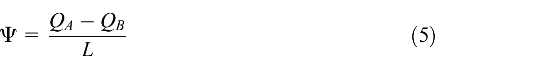
Where QB is the heat flow of the clear field of an assembly (W/K); QA is the heat flow of the assembly with a portion of the clear field replaced with intersections (W/K); and L is the assembly width (m), which represents the linear length of the intersection.
The point transmittance is similar to the linear transmittance but for point anomalies, such as beam end penetrations and intersections between linear details. The point transmittance χ (W/K) is a single additive of the amount of heat, as shown in equation (7)

Where, Q1 is the heat flow of the whole assembly unit with intersections (W/K), and Q2 is the heat flow of the assembly with no intersections (W/K).
In calculating the overall thermal transmittance of an entire building or wall, all thermal transmittances are categorized into three groups: clear field transmittance (Uo), linear transmittance (Ψ), and point transmittance (χ) (Hydro, 2016). The overall U-value (W/m2·K) is calculated as follows:

Where Uo is the clear field thermal transmittance (W/m2·K), Atotal is the total opaque wall area (m2), ψ is the point transmittance heat flow from the linear thermal bridge (W/(m·K)), L is the length of the linear thermal bridge (m), and χ is the heat flow from the point thermal bridge (W/K).
ASHRAE Fundamentals Handbook concluded that the area-weighted method is more complicated than the linear transmittance method for a whole-building elevation when accounting for 3D intersections (ASHRAE, 2017).
Detailed numerical simulation
Experimental measurements of an element’s thermal behavior can be expensive, especially for large-scale specimens. Computational numerical simulation is considered a practical alternative, as this method is cost-effective and accurate. There are many thermal analysis programs designed to simulate thermal problems in two dimensions, such as THERM, HEAT2, Energy2D (Xie, 2012), and three dimensions, such as ANSYS, ABAQUS, HEAT3, and SIEMENS. A number of studies on masonry walls have been conducted to improve and validate the simulation approaches with experimental data (del Coz Diaz et al., 2006; Desjarlais and McGowan, 1997; Norris et al., 2012). Those studies showed good agreements (typically about 3% discrepancy) between numerical simulation and experiment results. Validated simulation approaches were then used to simulate the thermal performance of other wall configurations. The collection of data (i.e. a catalog) allows designers to have quick and easy access to an accurate thermal performance of many design options (Hershfield, 2016; Norris et al., 2012).
Experimental testing for R-value
Effective thermal resistance is influenced by many factors, such as air leakage, thermal bridging, moisture content, physical conditions, and installation defects. Sometimes, the accurate value can only be captured by testing. Therefore, tests are often used to evaluate and improve the approaches and accuracies of analytical calculations and numerical simulations.
Laboratory testing using hot box apparatus
The hot box method is the most common experimental approach to determine the thermal performance of assemblies with large dimensions (Spitler, McQuiston and Lindsey 1993). ASTM C1363 2011 (ASTM, 2011) provides minimum requirements to test the thermal performance of building assemblies under steady-state conditions and for homogenous and non-homogeneous specimens (McCall, 1985).There are two types of hot box apparatuses: the guarded hot box and calibrated hot box, as shown in Figure 8.
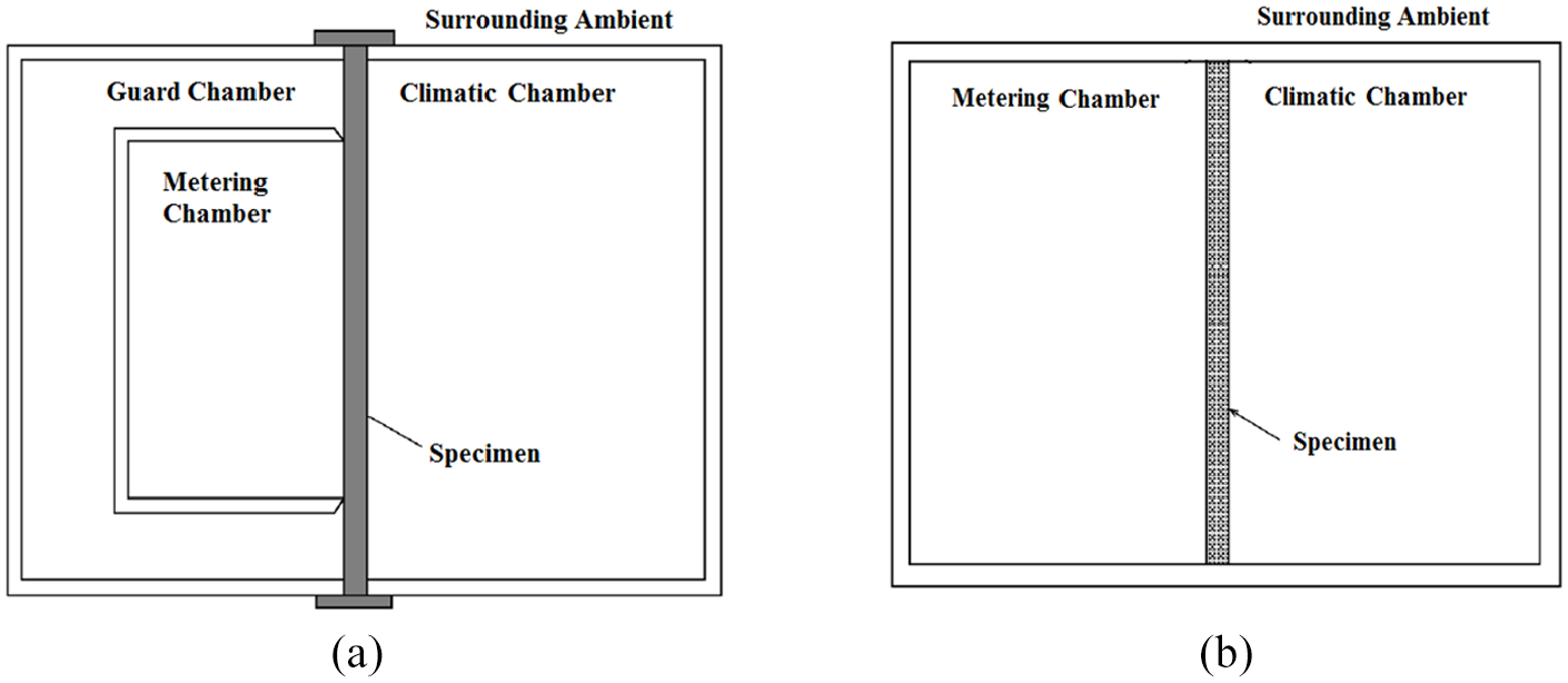
(a) Typical guarded hot box and (b) typical calibrated hot box (ASTM, 2011).
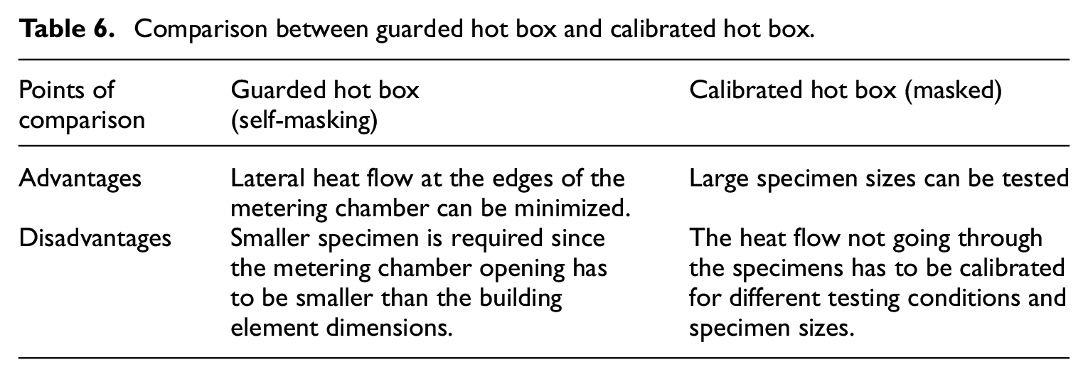
A comparison between the advantages and disadvantages of the two hot boxes is shown in Table 6. The main components of both hot box apparatuses are the metering chamber, climatic chamber, loading frame, and ambient space surrounding the specimen. These four components should be designed to provide the required conditions for testing, such as air velocity, air temperature, and radiation conditions. The expected output information from these chambers provides an accurate measurement of the net heat transfer through the specimen.
Comparison between guarded hot box and calibrated hot box.
Hot boxes typically measure heat transfer through a specimen under steady-state conditions when the environmental conditions on both sides of the specimen are constant. Tests are typically performed with a significant temperature difference across the specimen. Air velocities on both sides of the specimen are measured and remain constant during the test. Once the steady-state condition is reached, the net heat flow (Q) through the specimen is carefully measured or calculated (ASTM, 2011). The following general equation is used to calculate the R-value of a specimen:

Where Q is the heat flow through the metered area (W), R is the thermal resistance of the specimen (m2·K/W), A is the metered area (m2), and ΔT is the difference in surface temperature across the specimen (K).
Aside from measuring R-values under steady-state conditions, R-values can also be measured under dynamic conditions with temperature changes. Dynamic tests can be performed, with the calibrated hot box, by maintaining a constant indoor air temperature while the outdoor air temperature is varied using a predetermined time versus temperature relation. The energy required to maintain a constant indoor air temperature is recorded as a function of time (Van Geem et al., 1982). The dynamic response of a hot box to dynamic excitation needs to be determined and separated from the response of the specimens (Brown and Stephenson, 1993a, 1993b). Brown et al. (1993b) presented the test procedure to measure dynamic heat transfer characteristics of full-scale wall specimens using a guarded hot box apparatus. Fiorato (1979) used a hot box apparatus to study different masonry wall configurations based on dynamic and steady-state conditions. The ASHRAE research project 1365-RP’s (Roppel et al., 2012) used guarded hot box tested, under steady-state conditions. Also, the experimental results using hotbox of many previous studies were used to validate recent numerical simulations’ results or calculation methods (Brown and Stephenson, 1993a, 1993b; Desjarlais and McGowan, 1997; Kosny, 1995; Kosny and Christian, 2001).
R-value measurements using thermal imaging
Thermographic imaging mainly consists of taking photographs in the infrared spectrum. The camera estimates and creates an image of long-wave radiation that is converted to the visible color scale. From these long-wave measurements, the temperature can be deduced. Emissivity must be assumed in this technique as the camera is incapable of recognizing the boundary between different elements, such as bricks and steel door frames. The emissivity assumption is considered to be one of the main sources of error in this technique. In addition, ASTM C1060-11a provides practical techniques and recommendations for the thermographic inspection of insulation installations in envelope cavities of frame buildings (ASTM, 2015b). Thermographic imaging is considered a practical and rapid method for inspecting and analyzing improperly installed or damaged insulation. However, Care must be taken during the interpretation of thermal bridging from thermographs because some temperature irregularities can be caused by air leakage (Barnes et al., 2013).
A lower-cost automated approach for rapidly evaluating the energy effectiveness of buildings is needed. An automated measurement approach to estimate building envelope R-values were presented by Alshatshati et al. (2017). Estimated wall and window R-values used in this approach were obtained by thermal imaging. The measured exterior wall temperatures were calibrated to known and measured R-values for a small group of residences. In this approach, two steps were performed: (1) visual imagery was used to determine wall emissivity based on the color of the walls and the temperature was estimated, then (2) a random forest model was developed using the training set obtained from the studied residences with a known R-value. This model can be used to estimate the R-values of other houses based on their measured exterior temperatures using thermal imaging. Results showed that the proposed approach was capable of accurately estimating envelope thermal characteristics and capacitances
On-site overall R-value measurements for masonry walls
The thermal performance of new building design can be evaluated through laboratory tests and numerical simulations, but evaluating the thermal performance of existing masonry walls is more complicated due to many factors, such as the degradation of material properties over time and imperfect workmanship. Practical and non-destructive and in situ measurements are needed for the evaluation process.
ASTM C1155-95 (ASTM, 2013) provides guidelines to obtain in situ measurements of heat fluxes and temperatures and uses the data to compute the thermal resistance of building envelopes. This practice provides estimation methods for thermal resistance values in the range of temperatures obtained during the measurement of temperatures and heat fluxes. Two techniques are presented: the summation technique and the sum of least squares technique.
Deconinck and Roels (2016) presented a comparison of in situ characterization methods determining the thermal resistance of building components. The most accepted method is the average method described in ISO 9869 (Rasooli and Itard, 2018). Essentially, the average method relies on semi-stationary boundary conditions, using averaged measurement data as an approximation of stationary conditions. For the method to be valid, the averages should be taken over a sufficiently long period. More dynamic advanced data analysis methods, such as regression modeling, Auto-Regressive with eXogenous input (ARX)-modeling or stochastic gray-box modeling, can be used to handle dynamic conditions. A comparison of these dynamic methods was completed for simulated measurements of an insulated cavity wall in a moderate European climate. Performances were tested for actual measurements of a similar test wall. These results showed that the semi-stationary methods were more practical and reliable when applied to winter measurements. The dynamic methods were more complex but offered more versatile applications.
An investigation presented by Soares et al. (2019) reviewed laboratory and in situ non-destructive methods to evaluate the thermal transmittance and behavior of walls. The research described five methods: heat flow meters, guarded hot plates, guarded hot boxes, calibrated hot boxes, and infrared thermography. Regarding the in situ methods, the majority of studies found in the literature refer to homogeneous or moderately-homogeneous walls, and more research should be conducted to provide reliable methodologies that use quantitative infrared thermography to measure the thermal transmittance of non-homogeneous construction elements. It was concluded that further research is required to quantify the influence of several parameters, such as emissivity, surface heat transfer coefficients, air velocity, and thermal bridges. Calculating thermal resistance from in situ data represents in-service conditions; however, field measurements of temperature and heat flux may not achieve the accuracy obtainable in laboratory apparatuses.
Research gap and future recommendations
Many studies have investigated the thermal performance of masonry concrete blocks, introduced insulation patterns, and estimated thermal efficiency using different approaches and techniques. There are few methods to estimate the R-value of a complete wall, including all of its components (i.e. air gaps, ties, and shelf angles). Some of these methods are insufficient due to limitations to specific cases and conditions (e.g. weighted area method). These methods must be modified and further investigated to provide a reliable estimation method for the effective R-value of different masonry walls that can represent any detail required with no limitations on the conditions, configurations, or material properties. The remaining methods depend primarily on computer simulations (e.g. linear and point transmittance). There is a need for practical methods that are independent of computer simulations and experimental tests to simplify the application process for designers. These practical methods should be able to provide sufficient accuracy without comprising efficiency and increasing costs. The significance of such work would help provide design guidelines for the construction industry. It would also help designers predict the R-value of masonry walls with different conditions and analyze the effect of interruptions, such as intersections of slabs or balconies, on the overall thermal performance. It is apparent from the literature reviewed that the estimation of a masonry wall’s thermal performance is a sensitive process that can affect the total estimated energy use of a building.
A research gap was also found on significant topics that have a direct effect on the thermal performance of masonry walls and buildings (e.g. the relationship between the structural and thermal performance of masonry walls), the insulation aging effects, and the effect of building components on the whole building thermal analysis rather than one element (e.g. walls). Few types of research address the thermal inertia of masonry walls. Unlike thermal insulation that can be characterized by thermal resistance, thermal inertia (capacity of a material to store heat and to delay its transmission) is difficult to be quantified by a single parameter. Different indicators to characterize thermal inertia have been used over years. Thus, coefficients like thermal diffusivity or the effective heat capacity per unit area are widely used. This property also has a significant effect on the effective thermal resistance between the interior and the exterior; besides, the thermal inertia causes a link between the maximum external temperature and the maximum instantaneous heat flux transmitted to the interior. Both effects can be used to reduce the energy consumption of the HVAC equipment. Further research is required to address these factors and topics.
Conclusion
The purpose of this review is to provide a critical discussion of the significant factors that influence the thermal performance of masonry veneer walls. Different methods of thermal design and evaluations of masonry walls were presented and discussed by reviewing the available research and practice literature. The effects of different wall components (e.g. concrete blocks, grout, mortar, ties, shelf angles, insulation, and veneer air gaps) and thermal bridging were also discussed, as well as subtle design considerations that influence the thermal performance of a wall, such as the choice of material for concrete blocks masonry ties and shelf angles. Analytical approaches (e.g. the area-weighted method) were presented to demonstrate the resistance calculations for concrete masonry units, while the linear transmittance method and experimental investigations were discussed to illustrate efficient R-value measurements and calculations. The advantages and limitations of each method were also provided (see appendix Table A8). Technical and practical challenges were highlighted, as well as the precautions required to achieve the best thermal performance.
From the review, it is clear that the thermal properties of materials are one of the dominant factors in thermal resistance and should be carefully considered. Tie material and design can have a significant impact on the effective R-value of masonry veneer walls. Traditional steel shelf angles appeared to be the highest contributors to thermal bridging in concrete masonry cavity walls. The R-value reduction of assemblies depends on the shape and materials of shelf angles and ties. Different shapes were introduced to the market to minimize the reduction in thermal resistance. There are many recommendations for the fabrication of stainless steel shelf angles and ties, which could decrease their thermal bridging effects. This study summarizes critical information and recommendations that will help improve the thermal design of masonry walls, hence reducing the energy consumption of buildings.
Footnotes
Appendix
A summary of the effects of different parameters on the overall R-value of masonry walls based on literature, along with recommendations to improve the thermal performance of masonry walls is presented in Table A7.
Declaration of conflicting interests
The author(s) declared no potential conflicts of interest with respect to the research, authorship, and/or publication of this article.
Funding
The author(s) disclosed receipt of the following financial support for the research, authorship, and/or publication of this article: the National Sciences and Engineering Research Council of Canada (NSERC).