
Abstract
The static/dynamic stiffness of the ball screw feed system has an important influence on the machining accuracy and stability of the machine tool. To study the static/dynamic stiffness characteristics of the ball screw feed system under different support methods, a dynamic model of the ball screw feed system is established using the lumped parameter method. Then, the variation of the system’s static/dynamic stiffness is studied, and the influence of workpiece mass and placement position on the system’s static/dynamic stiffness is also concerned. The results show that as the stroke increases, the static/dynamic stiffness of the system with fixed supports at both ends first decreases and then increases, while that of the system with one end fixed and the other end floating always decreases. Comparing the two systems, the dynamic stiffness of the one with fixed supports at both ends is more sensitive to the workpiece’s mass and placement position. At the same time, as the workpiece mass increases, the natural frequency of the ball screw feed system decreases. The closer the workpiece is to the center of gravity of the worktable, the smaller its influence on the system’s natural frequency.
Introduction
Ball screw feed systems are widely used in CNC machine tools to achieve linear feed due to their advantages of high transmission efficiency, high positioning precision, and stable transmission performance. To adapt to the rapid development of science and technology, high-end CNC machine tools urgently need improvements in accuracy and efficiency; therefore, it is crucial to enhance the machining accuracy of CNC machine tools while ensuring the efficiency. The time-varying characteristics are the key factors affecting the motion accuracy of ball screw feed systems, which are mainly related to the servo control system and factors in the mechanical structure such as nut position, load, temperature, and joint friction. Under high-speed and high-precision working conditions, the ball screw feed system needs to maintain high motion accuracy and stability.1–3 The time-varying characteristics of static and dynamic stiffness have a significant impact on the motion accuracy and stability of ball screw feed systems.4,5 The deformation of the structure under static load reflects its static stiffness, while the natural frequency of the structure is an indicator of the dynamic stiffness of the ball screw feed system. Properly matched static stiffness values balance wears, errors, stability, and service life of the feed system. In contrast, high dynamic stiffness can effectively suppress vibration, reduce noise, and minimize the dynamic error of the system.
Dynamic modeling is the foundation for analyzing the system’s dynamic characteristics (e.g. stiffness, vibration, error). Zhang et al. 6 constructed a dynamic model using a hybrid scientific approach, which breaks through the limitations of single-method modeling and focuses on how changes in worktable position affect the system’s dynamic properties. Duan et al. 7 and Zhang et al. 8 both built lumped mass dynamic models based on the Lagrange equation—this method simplifies the system into discrete mass blocks (e.g. motor rotor, worktable) and derives motion equations via energy analysis, featuring simplicity and high efficiency but limited accuracy in describing local elastic deformation. Gu and Zhang, 9 Zou et al., 10 and Zhang et al. 11 separately adopted the Newton-Euler method to establish lumped mass models for single-degree-of-freedom feed systems; rooted in force-moment balance, it directly analyzes forces on each mass block and intuitively reflects the force-motion relationship, suitable for simple-structured systems. Additionally, Zhang et al., 12 Wu et al., 13 and Vicente et al. 14 created hybrid element models by combining the Ritz series with the energy method—they use the Ritz series to approximate structural elastic deformation (e.g. screw bending) and divide the system into elastic and lumped mass elements, balancing accuracy and efficiency to make up for the shortcomings of lumped mass models.
The system’s accuracy, stiffness, and stability are affected by multiple coupled factors. In terms of temperature, Man et al. 15 systematically reviewed thermal error research in ball screw systems, summarizing sources (e.g. screw friction heat, motor heat) and key directions (thermal error modeling, compensation), while pointing out future challenges. For joint characteristics (a stiffness weak link), Chen et al. 16 built a joint model based on virtual materials (instead of traditional spring-damper simplification) to analyze time-varying characteristics, revealing how joint stiffness changes under long-term operation or load fluctuations. Regarding load and inertia, Su et al. 17 constructed a mechatronic coupling model and studied the inertia ratio (worktable vs motor rotor inertia) impact on dynamic error, finding improper ratios increase errors. Shi Panpan 18 researched coupling stiffness modeling and static stiffness matching design between feed systems and verified the correctness of the results by using finite element simulation. Chen et al. 19 established a static contact stiffness model for non-uniform load distribution, analyzing how uneven contact angles/forces affect axial stiffness; Yang et al. 20 further considered speed/acceleration effects, building a dynamic contact deformation model and discovering high-speed motion intensifies contact force fluctuations and destabilizes dynamic stiffness.
To address practical engineering issues (selection, installation, parameter identification, stiffness matching), relevant studies provide targeted solutions. For selection and maintenance, Yang 21 outlined a “selection-calculation-installation-maintenance” framework for ball screws, clarifying key selection parameters (e.g. rated load, lead), analyzing installation deviation impacts, and emphasizing lubrication/cleaning requirements. For parameter identification, Wu and Chen 22 used a particle swarm-genetic hybrid algorithm to identify axial dynamic parameters (e.g. stiffness, damping)—this algorithm combines global and local optimization capabilities for accurate identification, aiding servo control tuning. Xu et al. 23 compared two common screw-bearing systems (angular contact, thrust ball bearings), analyzing their stiffness and load capacity to guide selection for different conditions (high-speed light-load vs low-speed heavy-load). In stiffness optimization, Wang et al. 24 modeled contact stiffness via preload-friction torque correlation, supporting dynamic preload compensation to suppress stiffness fluctuations. Oyanguren et al. 25 analyzed thermal deformation’s chain effect: screw thermal deformation changes nut preload, which in turn alters contact stiffness, laying a foundation for coordinated thermal error compensation and preload optimization. Stoica and Stan 26 found that enhancing screw stiffness significantly reduces positioning error in CNC machines with indirect measurement systems. In energy optimization, Sato et al. 27 optimized workpiece placement in five-axis machines to cut feed system energy consumption while ensuring machining accuracy.
In summary, scholars at home and abroad have carried out extensive research on the static/dynamic stiffness and dynamic characteristics of ball screw feed systems, forming a multi-dimensional research system covering modeling, analysis, optimization, and application, which has laid a solid theoretical and technical foundation for the improvement of system performance. However, it is worth noting that in the actual machining process, there is still room for further deepening in the existing research on the influence of screw support methods, workpiece mass, and placement position on the static/dynamic characteristics and machining accuracy of the system. On the one hand, the support methods of the bearings at both ends of the ball screw are mainly divided into two types: one is that both ends of the bearings adopt fixed support (fixed-fixed support), and the other is that the bearing at the motor end of the screw is fixed while the bearing far from the motor end is floating (fixed-floating support). The stiffness distribution and vibration characteristics of the system under different support methods are significantly different, but the quantitative influence mechanism on machining accuracy has not yet formed a unified analysis standard. On the other hand, the size of the workpiece mass will change the system load inertia, and different placement positions will lead to changes in the load distribution state. Both of them will indirectly affect the force deformation and dynamic response of the screw, thereby affecting the machining accuracy. However, current studies mostly analyze the influence of load or workpiece position separately, lacking research on the system characteristics under the coupling effect of the two.
In this study, static/dynamic stiffness analysis of ball screw feed systems under different support configurations is carried out, with full consideration of workpiece mass and placement position. Through comparative verification of different support methods and in-depth exploration of the coupling influence of workpiece mass and placement position, more accurate theoretical basis can be provided for the optimization of the support method of the ball screw feed system and the design of the workpiece clamping scheme, which is of great engineering practical significance for further improving the machining accuracy and efficiency of the system. The structure of this paper is organized as follows: A dynamic model of the ball screw feed system is constructed in Section “Dynamic modeling,” laying a theoretical foundation for subsequent stiffness analysis. Section “Comparative analysis of static stiffness” conducts a comparative analysis of static stiffness under different support configurations. Section “Comparative analysis of dynamic stiffness” carries out a comparative analysis of dynamic stiffness. Section “Dynamic characteristics analysis of the ball screw feed system considering workpiece mass and placement position,” with full consideration of workpiece mass and placement position, performs a comparative analysis of the dynamic stiffness of the ball screw feed system under different support configurations, aiming to reveal the coupled effects of support forms, workpiece mass, and placement position on the system’s dynamic stiffness. Finally, the conclusions are drawn in Section “Analysis of the sensitivity of dynamic stiffness of different support methods to workpiece mass and position.”
Dynamic modeling
In the ball screw feed system, the permanent magnet synchronous motor drives the lead screw through the coupling, and then the lead screw nut pair converts the screw rotational displacement into the axial displacement of the nut to realize the feed work. The core components of the system are the motor, bearing, worktable, lead screw, nut pair, and steel guide. Based on structural analysis and practical experience, considering the structural characteristics and the degree of influence of each component on system dynamics, the bearing, screw-nut, coupling, and guide-slide dynamic joint are regarded as massless spring units; Due to the simple structure and large mass of the worktable, it is regarded as a rigid body; According to the position of the lead screw nut, the lead screw is equivalent to three mass blocks, in which the lead screw is in contact with the nut and moves axially as one mass block, and the change of the other two mass blocks is determined by the displacement of the lead screw nut, and the three are connected by a massless spring unit.
This modeling method guarantees model accuracy and improves efficiency, and the feed system simplifies the model as shown in Figure 1.
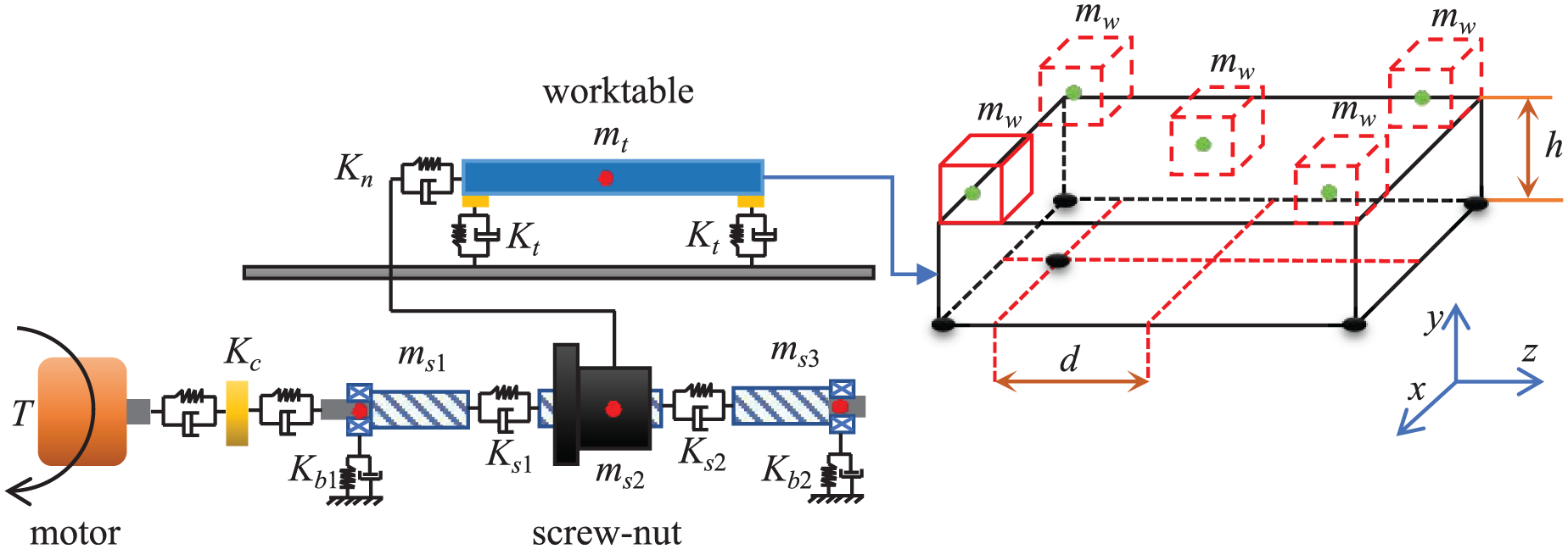
Simplified model of the ball screw feed system.
When the bearings at both ends are fixed at the same time, both bearings have shaft and radial loads, and the assembly drawing is shown in Figure 2(a) 28 ; When floating away from the motor end bearing, the axial load and stiffness of the end bearing are zero, and the assembly drawing is shown in Figure 2(b). 28

Assembly diagram: (a) fixed support at both ends and (b) one end fixed and one end floating support.
Based on the Lagrange equation, the centralized parameter method is used to construct the mechanical dynamics model of the system.
Kinetic energy calculation
The total kinetic energy of the system is obtained from the sum of the kinetic energy of the left lead screw, the middle lead screw, and the right section lead screw. The kinetic energy of the worktable. It can be expressed as:

Where T is the total kinetic energy of the system; T i is the kinetic energy of the structural member i (i = 1, 2, 3, 4).

Where
Potential energy calculation
The sum of the potential energy of the intermediate lead screw in contact with the left lead screw, the right lead screw, and the nut, and the potential energy of the transmission part and the worktable is the total potential energy of the system.
This can be expressed as

Where V is the total potential energy of the system; V i is the potential energy of the structural member i (i = 1, 2, 3, 4).

Where K
c
is the rotational stiffness of the coupling; ξ
m
is the rotational displacement of the motor shaft; K
b
1, K
b
2, K
n
, and K
g
are stiffness matrices of bearing, lead screw nut pair, and guide-slide pair, respectively. K
b
1 = diag(K
xb
1, K
yb
1, K
zb
1, K
ub
1, K
vb
1, K
wb
1), K
b
2 = diag(K
xb
2, K
yb
2, K
zb
2, K
ub
2, K
vb
2, K
wb
2), K
n
= diag(K
xn
, K
yn
, K
zn
, K
un
, K
vn
, K
wn
), K
g
= diag(K
xg
, K
yg
, K
zg
, K
ug
, K
vg
, K
wg
); K
s
1 and Ks2 are the equivalent stiffness vectors of the lead screw, K
s
1 = diag(K
xs
1, K
ys
2, K
zs
2, K
us
2, K
vs
2, K
ws
2), K
s
2 = diag(K
xs
2, K
ys
2, K
zs
2, K
us
2, K
vs
2, K
ws
2);
When the ball screw feed system is fixed support at both ends, the axial linear stiffness of bearing 1 and bearing 2 is the same, that is, K xb 1 = K xb 2; When the ball screw feed system is fixed at one end and floating at the other end, the axial stiffness of bearing 2 is zero, that is, K xb 2 = 0.
Calculation of the equivalent stiffness of the lead screw
As the lead screw is divided into three uncoupled elements, and in accordance with the calculation principle of cantilever beam stiffness in mechanics of materials, the equivalent stiffness is calculated without taking into account the coupling of deformations in all directions:

Where E is the elastic modulus of the material, I is the moment of inertia, G is the shear modulus, and l is the length of each lead screw.
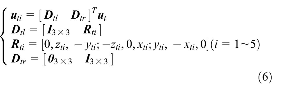
Where x
ti
, y
ti
, z
ti
are the coordinate values of the secondary equivalent points of the guide rail slider in the gravity center coordinate system of the worktable, with the unit of meters (m), which is determined by the size of the worktable structure and the distance from the nut to the center point of the worktable.
Bring the above equations (1) and (3) to the Lagrange equation:

Sort out the feed system-free damping kinetic equation:

Where
Based on this modeling approach, there is no need to calculate the displacement parameters of the equivalent mass point of the lead screw. Instead, only determining its equivalent mass and calculating its equivalent stiffness parameter are required. Which solves the influence of the lead screw’s rigid body movement on the accuracy of the results and simplifies the modeling process.
Comparative analysis of static stiffness
To verify the accuracy of the established dynamic model of the ball screw feed system, a comparative analysis of the static stiffness of the ball screw feed system with different support methods was carried out. The finite element model of the ball screw feed system was established using commercial finite element software, and the three-dimensional simplified model of the ball screw feed system was established through Solidworks, converted to x_t format, and imported into Workbench. Set the ball screw feed system material to structural steel, mesh the model using the automatic division method, simulate it with a Bushing unit at the joint of the motion sub-unit, and apply the unit axial load at the center of the worktable. The parameters of each component of the ball screw feed system are shown in Table 1, and the stiffness parameters of the joint are shown in Table 2.
Parameters of each component of the feed system.

Stiffness parameters of the joint part of the feed system.

(1) When the support method is fixed at both ends, the comparison results between the axial static stiffness of the system model and the simulation are shown in Figure 3(a). The comparison of calculation results is shown in Table 3, and the simulation results are shown in Figure 4(a). The results show that in this support form, during the stroke of the nut away from the motor, the axial static stiffness first decreases and then increases.
(2) When the support method is fixed at one end and floating at the other end, the axial stiffness of the bearing at the end far from the motor is 0. The comparison results of the axial static stiffness of the system model and the simulation are shown in Figure 3(b). The comparison of calculation results is shown in Table 4, and the simulation results are shown in Figure 4(b). The results show that under this support form, the farther the nut is from the motor, the lower the axial static stiffness.

The variation law of the axial stiffness with the stroke: (a) fixed support at both ends and (b) one end fixed and one end floating support.
Comparison of axial static stiffness calculation results of fixed support system at both ends.

Comparison of axial static stiffness calculation results of floating support system with fixed end at one end.


Simulation results of axial stiffness: (a) fixed support at both ends and (b) one end fixed and one end floating support.
The reason for the axial static stiffness of the system with two ends fixed support form first decreasing and then increasing is: when the nut is closer to the fixed bearings at both ends, the preload it receives is greater. At the same time, the bending deformation of the lead screw caused by the gravity of the nut and the worktable is smaller, the deflection is smaller, and the gap between the steel balls and raceways inside the lead screw is smaller, so the static stiffness is greater. When the nut and the worktable are closer to the middle position of the stroke, the static stiffness is smaller. The reason for the continuous decrease of the axial static stiffness of the system with one end fixed and one end floating support form is: in the process of the nut feeding from the fixed end to the floating support end, the lead screw undergoes elastic deformation. Due to the different constraints at both ends, the axial direction of the floating end has instability, and its support structure is more prone to deformation. There may be a certain axial gap, and as the stroke increases, the influence of the gap increases, resulting in a gradual decrease in axial static stiffness.
Comparative analysis of dynamic stiffness
In this section, a comparative study is conducted on the dynamic stiffness of the ball screw feed system with different support methods when the workpiece mass and placement position are the same, characterized by the first-order natural frequency of the system. Based on the above constructed dynamic model of the ball screw feed system, calculate the natural frequency of the ball screw feed system and verify it through finite element analysis software to complete the modal analysis of the ball screw feed system with different support methods. The comparison of the first-order natural frequency calculation results of the numerical model and the finite element simulation model is shown in Tables 5 and 6, and the simulation model is shown in Figure 5(a) and (b).
When the support method is fixed at both ends, the first-order natural frequency of the ball screw feed system first decreases and then increases with the increase of the stroke. The natural frequency is the lowest at the middle position of the stroke. The comparison between the model calculation value and the simulation is shown in Figure 10.
When the support method is fixed at one end and floating at the other end, the first-order natural frequency of the ball screw feed system decreases with the increase of the stroke. The comparison between the model calculation value and the simulation is shown in Figure 11.
First-order natural frequencies of fixed support systems at both ends.

First natural frequency of floating support system with fixed end at one end.


Simulation results of natural frequencies: (a) fixed supports at both ends and (b) one end fixed and one end floating support.
Based on the changes in the dynamic stiffness of the system with different lead screw support methods as the nut moves along the stroke as described above and referring to the factors affecting the change in the static stiffness of the system, the change rules of the static stiffness and dynamic stiffness of the system model are similar (Figure 6).
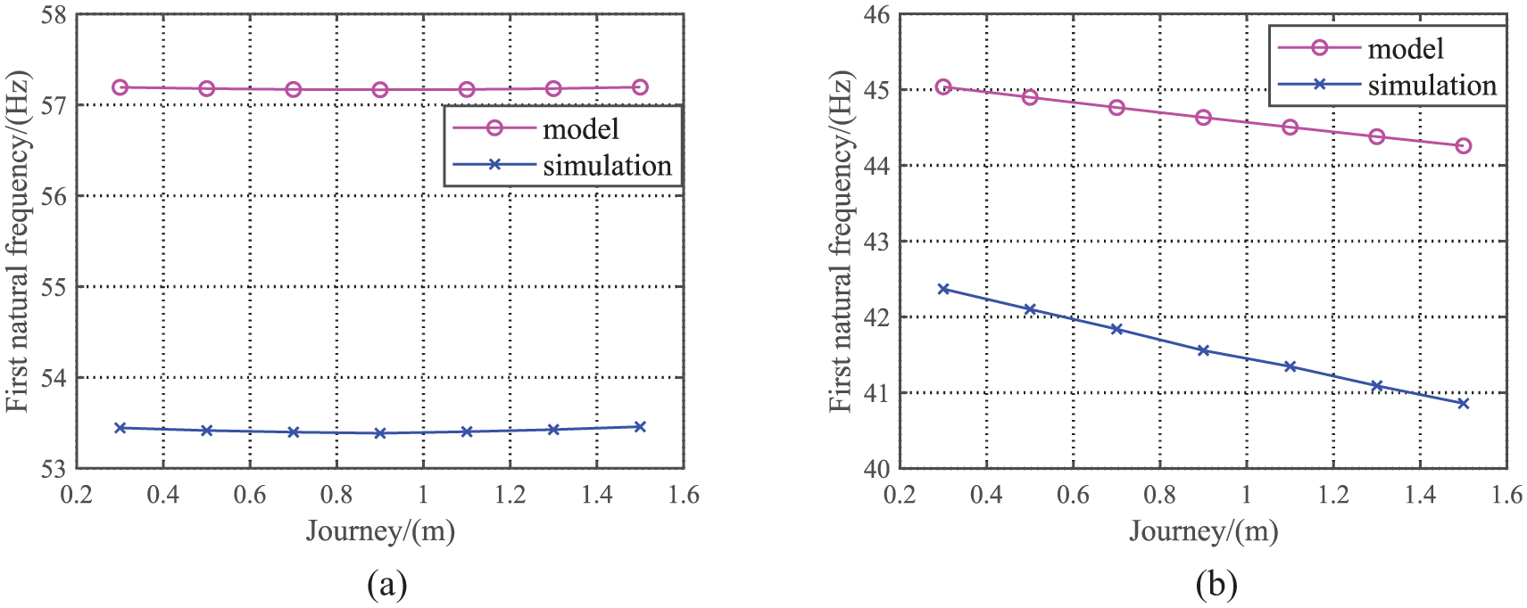
The variation law of the first natural frequency s with the stroke: (a) fixed supports at both ends and (b) one end fixed and one end floating support.
Dynamic characteristics analysis of the ball screw feed system considering workpiece mass and placement position
Based on the dynamic model of the built system, a cubic titanium alloy workpiece with a side length of 150 mm is selected and placed at five specific positions in the work surface, and the dynamic model of the built ball screw feed system is used to verify the finite element of the typical placement position of the workpiece, and the simulation results are shown in Figure 7, and the numerical model and finite element simulation are compared in Table 7.

Simulation results.
Comparison of first-order natural frequency calculation results (Hz).
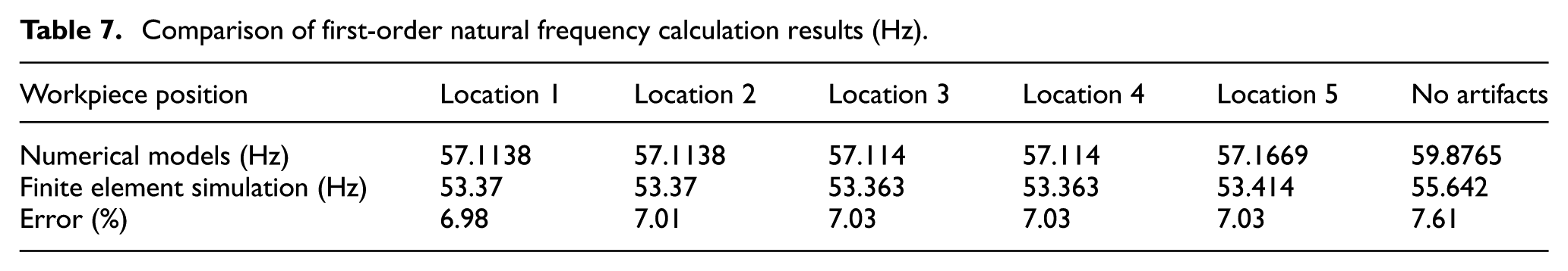
Comparing the numerical calculation model and the finite element simulation results, the error is kept within 10%, which shows that the model accuracy meets the calculation requirements and can carry out the dynamic characteristics analysis of the ball screw feed system considering the mass and placement position of the workpiece.
The mass and placement position of the workpiece will cause changes in the gravity center position of the moving parts of the ball screw feed system, thereby leading to changes in the system’s dynamic characteristics. As shown in Figure 8, in the conjoined coordinate system of the worktable,
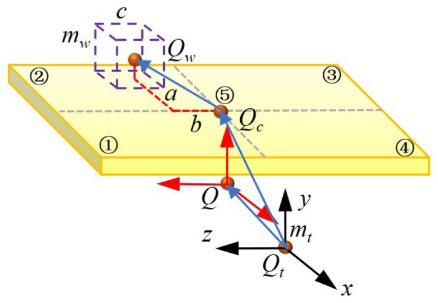
Effect of workpiece mass on the position of the gravity center of the table.
The gravity center of the worktable after considering the workpiece mass and placement position can be expressed as:

Where m w is the workpiece mass.

Where
According to the parallel axis theorem of the moment of inertia:

Where
The coordinates of each joint after considering the mass and placement of the workpiece can be expressed as:

Bring formulas (11) and (12) into the constructed dynamic model to carry out the dynamic characteristic analysis of the ball screw system. Among them, the first-order natural frequency of the system within the full stroke without a workpiece is shown in Figure 9. The influence of workpiece mass on the first-order natural frequency of the system is shown in Figure 10. The analysis of the first-order natural frequency of the system within the worktable surface is shown in Figure 11.

First-order natural frequency of a full-stroke system without a workpiece.
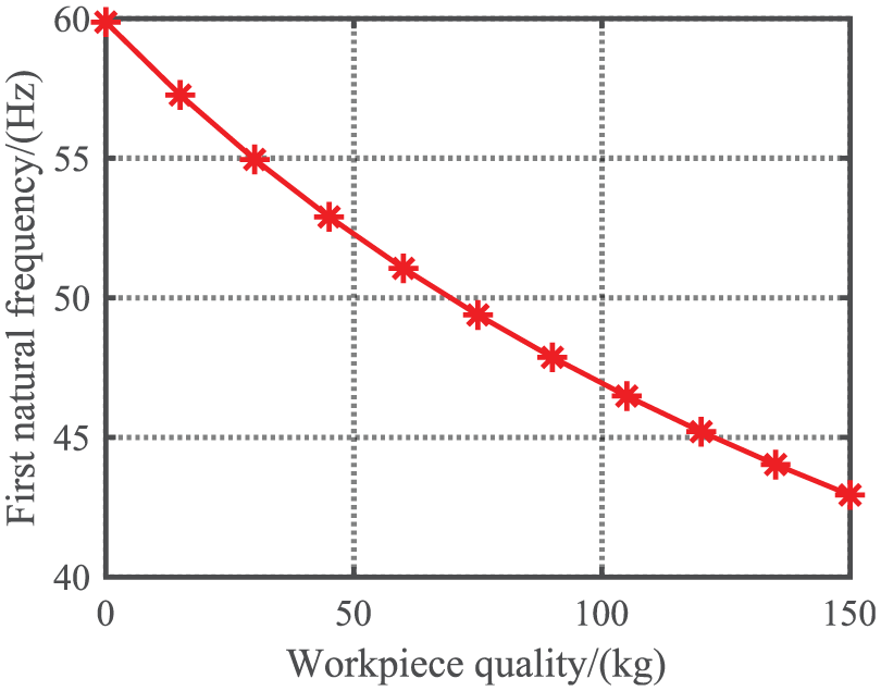
Effect of workpiece mass on the first natural frequency of the system.

First-order natural frequency distribution of the system within the work surface.
As can be seen from Figure 9, the dynamic characteristics of the constructed dynamic model in the entire domain of the ball screw feed system exhibit a concave curve distribution. This is different from the convex curve of considering the screw as an equivalent single rigid body 3 and is in line with the pattern of the hybrid dynamic model. 4 This indicates that the constructed lumped mass dynamic model can accurately describe the dynamic characteristics and their changes of the ball screw feed system with fixed supports at both ends throughout the full stroke. Meanwhile, it can be observed from Figure 9 that in the middle of the stroke, the first-order natural frequency of the ball screw system is relatively low.
It can be seen from Figure 10 that the workpiece mass has an important influence on the dynamic characteristics of the ball screw feed system. As the workpiece mass increases, the first-order natural frequency of the system decreases significantly. Therefore, in the actual machining process, attention should be paid to the influence of workpiece mass changes on the dynamic characteristics of the system.
As can be seen from Table 7, Figure 7, and Figure 11, the placement position of the workpiece will cause changes in the dynamic characteristics of the ball screw feed system. Among them, the farther away from the center of the worktable surface, the lower the first-order natural frequency of the system. At the same time, since the nut position is not at the center of the worktable, the distribution of the first-order natural frequency of the system within the worktable surface is not symmetrical, and the side of the nut is relatively high. Therefore, considering the above, in the process of practical processing, the workpiece should be placed as far as possible to the side of the nut and near the center of the worktable surface.
Analysis of the sensitivity of dynamic stiffness of different support methods to workpiece mass and position
Sensitivity analysis of dynamic stiffness to workpiece mass
Based on the dynamic model of the ball screw system established above, the lead screw nut pair position is fixed 0.9 m away from the motor, the workpiece is placed in the center of the worktable and its mass is changed (0–150 kg). The influence of workpiece mass on the natural frequency of the ball screw feed system with different support methods is shown in Figure 7.
In order to judge the sensitivity of the dynamic stiffness of the two support modes to the workpiece mass, let Δm
wi
be the relative workpiece mass, Δf
ai
and Δf
bi
be the relative natural frequencies of the two support modes, H
ai
and H
bi
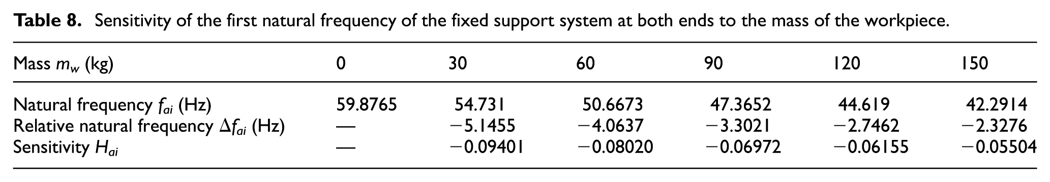
be the sensitivity of the dynamic stiffness to the workpiece mass, and the sensitivity of the dynamic stiffness of different support modes to the workpiece mass is shown in Tables 8 and 9, and the mean sensitivity
Sensitivity of the first natural frequency of the fixed support system at both ends to the mass of the workpiece.
Sensitivity analysis of the first natural frequency of the fixed end and the floating support system at one end to the mass of the workpiece.

The higher sensitivity of the fixed support system at both ends to workpiece mass compared with the support system with one fixed end and one floating end was verified using the statistical p-value. Five pairs of matched samples were selected (with workpiece mass (m w = 30–150 kg)). Each pair corresponded to the same workpiece mass, which eliminated sensitivity deviations caused by different masses. The paired samples t-test was adopted. This method is suitable for matched sample designs (each pair of sensitivity data corresponds to the same workpiece mass) and can exclude interference from mass differences, ensuring the reliability of the comparison between the two support systems. There are two Statistical Hypotheses. Null Hypothesis: There is no difference in sensitivity between the two groups, that is, the population mean of the difference (H ai −H bi ) equals 0 (the fixed support system at both ends is not more sensitive). Alternative Hypothesis: The population mean of the difference is less than 0 (H ai < H bi ). This indicates that the absolute value of sensitivity of the fixed support system at both ends is larger, meaning it is more sensitive. A one-tailed test was used (as the direction of the hypothesis was clear). The calculation results of the core statistical indicators are shown in Table 10.
Core statistical indicators.

Note. The negative value of sensitivity only reflects the physical meaning that “the natural frequency decreases as the mass increases.” The magnitude of the absolute value directly indicates the level of sensitivity.
The mean of differences (

Comparative analysis of dynamic stiffness sensitivity to workpiece position
Referring to the fourth section of this paper, place a cubic titanium alloy workpiece with a side length of 150 mm and a mass of 15.6 kg at five specific positions on the worktable. Conduct a comparative study on the sensitivity of the dynamic stiffness of the ball screw feed system with different support methods to the placement position of the workpiece.
Equations (11) and (12) were substituted into the dynamic model of the ball screw feed system and the dynamic characteristics analysis were carried out. The simulation results of the first-order natural frequency of the system with different support methods when changing the placement position of the workpiece are shown in Table 11. Define the natural frequency of the fixed support method system at both ends is F a (i), the sensitivity of the dynamic stiffness of the system to the workpiece placement position is L a = F a (max) − F a (min) = 0.051; Define the natural frequency of the system is F b (i), the sensitivity of the dynamic stiffness of the system to the workpiece placement position is L b = F b (max) − F b (min) = 0.021. From L a > L b , it can be seen that the dynamic stiffness of the ball screw feed system with fixed support at both ends is relatively sensitive to the workpiece placement position.
Sensitivity analysis of the first natural frequency of different support systems to the workpiece position.

Conclusion
During the machining process, the performance of the ball screw feed system ensures the working accuracy and stability of the machine tool. Considering that the support methods of ball screws are not the same in practical applications, in this paper, the ball screw feed systems with both ends fixed support and one end fixed and the other end floating support are taken as the research objects. The lumped parameter method is adopted to establish a dynamic model respectively, and a comparative study of static/dynamic stiffness is conducted. The results of static stiffness comparison and analysis show that: For the two ends fixed support method, when the nut moves away from the motor, the axial static stiffness of the system decreases first and then increases. For the one end fixed and the other end floating support method, the farther the nut is from the motor, the lower the axial static stiffness of the system. In the whole stroke, the ball screw feed system with fixed supports at both ends has higher axial static stiffness compared to the ball screw feed system with one end fixed and the other end floating support. Its first-order natural frequency is also relatively higher. It has better anti-vibration performance and better machining performance and stability. The results of dynamic stiffness comparison and analysis show that: When both ends are fixed, the first-order natural frequency of the ball screw feed system first decreases and then increases with the increase of the stroke, and the natural frequency at the middle position of the stroke is the lowest. When one end is fixed and the other end is floating, the first-order natural frequency of the ball screw feed system decreases with the increase of the stroke.
Simultaneously, the influence of the workpiece’s mass and placement position on the system’s dynamic stiffness is taken into account. From the analysis results of the system with fixed supports at both ends, it can be seen that the workpiece’s mass will cause the first order natural frequency of the ball screw feed to decrease. The larger the workpiece’s mass, the greater the decrease value. In addition, the placement position of the workpiece also has a certain impact on the system’s first order natural frequency. The closer the workpiece is to the center position of the worktable surface, the higher the system’s first order natural frequency, and the farther it is from the nut position, the lower the system’s first order natural frequency. The comparative analysis of feed systems with different support methods shows that the system with fixed supports at both ends of the bearings changes relatively significantly and has higher sensitivity when the workpiece’s mass increases and when the workpiece’s placement position is changed. The above has important guiding significance for the configuration design of the ball screw feed system and the position installation and mass control of the workpiece during the actual processing process.
Footnotes
Handling Editor: Chenhui Liang
Author contributions
Wang Chensheng was in charge of the whole trial and wrote the manuscript; Feng Yuhai assisted with simulation analyses. Su Fang was responsible for building the dynamic model. All authors read and approved the final manuscript.
Funding
The authors disclosed receipt of the following financial support for the research, authorship, and/or publication of this article: This work was supported by the Natural Science Foundation of Shanxi Province (202403021221177) and the Science and technology innovation project of Shanxi Provincial Education Department (2022L433, 2022L434).
Declaration of conflicting interests
The authors declared no potential conflicts of interest with respect to the research, authorship, and/or publication of this article.
Data availability statement
The data used to support the findings of this study are available from the corresponding author upon request.