
Abstract
Underwater archeology faces significant challenges in sampling sunken ships and buried artifacts, including high operational risks, low efficiency, high deployment costs, and potential damage to underwater cultural heritage. To address these issues, this paper presents the design and development of a biomimetic peristaltic robot inspired by the motion of earthworms. The robot comprises three primary components: a drilling mechanism, a peristaltic mechanism, and a transmission mechanism. The peristaltic mechanism features a multi-segment, serially connected Sarrus linkage module, with motion transmission achieved through a cylindrical cam mechanism. The profile of the cylindrical cam groove is precisely calculated based on the planned motion sequence. Additionally, an optimization scheme incorporating a dual-roller follower configuration for each slider unit is proposed to minimize sliding resistance at the ring slider of the Sarrus linkage module. To enable passive bending and passive steering, the cylindrical cam is segmented and connected via flexible shafts, bellows, and compression springs. A static analysis of key components is performed to ensure structural integrity and reliability. Finally, prototype experiments validate the robot’s capabilities in peristaltic motion, bending, and burrowing.
Keywords
Introduction
In underwater archeology, once submerged relics are detected using conventional methods such as multibeam sonar, side-scan sonar, and sub-bottom profiling, further sampling and analysis are needed to evaluate their specific conditions in muddy sedimentary environments. Currently, two primary approaches are used for retrieving samples from beneath the muddy sediment. One approach involves deploying archeologists for underwater diving to conduct exploration, video recording, and sampling. However, this method is time-consuming, inefficient, and poses significant safety risks, particularly in deep-water environments. The other approach involves constructing offshore drilling platforms to extract samples from below the seabed. While effective, this method requires extensive setup time, incurs high costs, and may cause substantial damage to underwater cultural heritage, making it less suitable for archeological research.
To mitigate sediment disturbance, researchers have developed various robots for subsurface sediment detection and sampling. France’s CNRS-developed Ocean One humanoid robot 1 features a multimodal tactile system that enables millimeter-level precision in artifact manipulation. Its force-sensitive manipulator employs adaptive algorithms to achieve non-destructive retrieval of artifacts made from various materials. Hotta et al. designed a lightweight underwater robot 2 that uses thruster-induced fluid dynamics to displace seabed sediments. Bianchi et al. developed a biomimetic robot 3 inspired by cownose rays, employing flexible pectoral-fin mechanisms to enable multi-degree-of-freedom locomotion, thereby enhancing precision in seabed exploration. Harbin Engineering University’s MUV robot 4 incorporates optimized thruster configurations and flow-field control, reducing sediment disturbance by 70% and enabling centimeter-scale near-seafloor observation—an important advancement for the recovery of fragile artifacts. However, the aforementioned robots are mainly suitable for shallowly buried relics and remain inadequate for the retrieval of cultural artifacts located at greater depths beneath the sediment.
To address these challenges, this paper proposes a biomimetic earthworm-inspired peristaltic robot designed for subsurface sediment detection and sampling. The robot is compact and capable of peristaltic burrowing under the actuation of a single motor. When encountering hard obstacles such as rocks during downward exploration in sediment, it can passively move around them. By utilizing this robot for subsurface detection and sampling, potential damage to fragile underwater relics can be significantly minimized, offering a novel technological approach and solution for underwater archeology.
Nature has long served as a source of inspiration for the development of peristaltic robots. Many organisms, including snakes, earthworms, snails, and inchworms, rely on body flexibility and traveling wave locomotion for movement. Burrowing animals, such as earthworms, propel themselves through soil by generating retrograde peristaltic waves through the alternating contraction of muscle layers.5–7 Drawing from these biological systems, researchers have developed various robots capable of navigating and burrowing through real soil or granular media. These robotic systems typically consist of a propulsion unit, inspired by the peristaltic crawling of earthworms, and an excavation unit, which facilitates efficient tunneling through densely packed soil.
Some studies have achieved peristaltic locomotion by regulating air pressure in multiple chambers, enabling sequential expansion and contraction to propel the robot forward. Isaka et al. developed a drilling robot inspired by earthworm locomotion for seafloor exploration, utilizing rubber tubes and pneumatic cylinders to replicate peristaltic motion. 8 Similarly, Das et al. designed a soft robot capable of generating tunable peristaltic deformations, allowing efficient navigation through granular media while minimizing friction during soil penetration. 9 Their robot consisted of five modular units, each containing a hollow cylindrical pneumatic chamber. In 2023, they further introduced a modular soft robot based on a peristaltic soft actuator (PSA). 10 This PSA demonstrated two active configurations, transitioning from a neutral state by alternating between positive and negative pressure. Yang and Zhang demonstrated flexible crawling on both horizontal and vertical surfaces using pneumatic actuation combined with an underactuated steering mechanism. 11 Li et al. developed a multi-modal, maneuverable soft robot capable of locomotion both inside pipelines and on flat surfaces. 12 This robot featured six vacuum pressure-driven actuators (VPPAs) and two positive pressure-driven actuators (PPPAs), effectively mimicking the crawling motion of an earthworm. However, pneumatic systems are inherently complex, leading some researchers to explore alternative actuation methods.
To address these challenges, shape memory alloys and fiber-based actuators have been employed in peristaltic robotics. Seok et al. developed a helical nickel-titanium (NiTi) coil, inspired by the muscle arrangement of earthworms, and validated its sequential peristaltic motion through numerical simulations and experiments. 13 Boxerbaum et al. utilized a braided mesh structure to enable continuous peristaltic motion and introduced an analytical model to characterize its movement. 14 Connolly et al. achieved diverse actuator motion patterns, including axial extension and radial expansion, by adjusting fiber angles, enhancing peristaltic crawling efficiency. 15
Expansion and contraction mechanisms have also been explored in earthworm-inspired robotics. Omori et al. developed a dual-pantograph system for a planetary subsurface explorer designed to excavate lunar soil and conduct scientific investigations.16,17 Fang et al. introduced an origami-inspired robotic system that utilizes spherical origami structures to achieve both axial and radial deformations, generating peristaltic waves that mimic earthworm movement. 18 Liu et al. successfully replicated the anchoring and locomotion mechanisms of earthworms in soil by integrating Kirigami-inspired skin with radially expandable pneumatic actuators. 19 Zhan et al. further mimicked the alternating contraction and extension patterns of earthworm segments using a servo motor-driven mechanism incorporating spring-steel belts. 20
The above study of earthworm-like robots reveals challenges such as complex structures, multiple actuators, and difficulties in control. In this paper, we propose a novel biomimetic earthworm-inspired peristaltic robot featuring series-connected Sarrus linkage modules. By utilizing radial and axial expansion-contraction movements, the robot replicates the peristaltic motion of an earthworm, enabling propulsion through sediment. Additionally, we introduce a multi-section cylindrical cam-driven flexible shaft transmission mechanism. By precisely designing and calculating the cylindrical cam profile, this transmission mechanism ensures the synchronized actuation of multiple Sarrus linkage modules while maintaining flexibility to bend and adapt to environmental constraints. The proposed robot features a compact and streamlined structure, requires minimal actuation, is easy to control, and can passively adjust its trajectory upon encountering obstacles. These advantages make it a promising tool for minimally invasive underwater archeological exploration.
Overall structure
The waveform of segmental changes during earthworm peristalsis exhibits periodicity and repeatability. To simplify its motion model, four consecutive segments of the earthworm are selected, as shown in Figure 1. In the figure, red numbers indicate node indices, blue boxes represent individual segments with their corresponding segment numbers, green small boxes denote the connection between segments, and green semi-ellipses depict the earthworm’s head and tail.

Simplified motion diagram of an earthworm.
In the initial state, the circular muscles of the first segment contract while the longitudinal muscles relax, causing the segment to elongate and become thin. Meanwhile, in the second, third, and fourth segments, the longitudinal muscles contract while the circular muscles relax, making these segments short and thick, thereby anchoring the body.
The peristaltic movement proceeds as follows:
Step 1: The longitudinal muscles of the first segment contract while the circular muscles relax, causing the segment to shorten and thicken, securing the body in place. Simultaneously, the circular muscles of the second segment contract while its longitudinal muscles relax, elongating and thinning the segment. The third and fourth segments remain in a contracted state, anchoring the body.
Step 2: The second segment’s longitudinal muscles contract while its circular muscles relax, shortening and thickening the segment for anchoring. Simultaneously, the circular muscles of the third segment contract while its longitudinal muscles relax, elongating and thinning the segment. The first and fourth segments remain unchanged in their contracted state, providing stability.
Step 3: The third segment’s longitudinal muscles contract while its circular muscles relax, shortening and thickening the segment for anchoring. Simultaneously, the circular muscles of the fourth segment contract while its longitudinal muscles relax, elongating and thinning the segment. The first and second segments remain in their contracted state, ensuring body stability.
Step 4: The fourth segment’s longitudinal muscles contract while its circular muscles relax, shortening and thickening the segment for anchoring. Simultaneously, the circular muscles of the first segment contract while its longitudinal muscles relax, elongating and thinning the segment. The second and third segments remain unchanged in their contracted state, maintaining body stability.
Upon completing Step 4, the sequence returns to the initial state, completing one full cycle of peristaltic motion. Through this cyclic process, the earthworm successfully propels itself forward.
Based on the peristaltic movement of the earthworm described above, a peristaltic robot has been designed, as shown in Figure 2. The robot consists of three main components: the drilling mechanism, the peristaltic mechanism, and the transmission mechanism. The drilling mechanism is responsible for enabling axial tunneling. The peristaltic mechanism facilitates the forward movement of the robot through peristaltic motion. The transmission mechanism transfers the rotational motion of the single driving motor, located at the tail of the robot, to the various moving parts, following the established motion pattern. The transmission mechanism employs flexible components, allowing the bio-inspired peristaltic robot to maintain its transmission function even when encountering obstacles and bending during tunneling.

3D model of the robot.
Drilling mechanism
The primary functions of the drilling mechanism are to enable axial drilling and provide radial support and expansion. The mechanism uses a gradually expanding hole technique and features a conical design, ensuring a smooth transition. At the top, a conical spiral cutting blade is installed to cut through obstructive materials encountered during peristaltic motion, such as gravel and soil. The structural schematic is shown in Figure 3.

Schematic diagram of drilling mechanism.
The drilling mechanism is equipped with a spiral mud guide groove that transports the cut materials to the rear of the mechanism, aiding in the removal of debris. Additionally, it provides radial support and expansion, preventing collapses during drilling and clearing a path for the robot’s passive steering mechanism and umbrella folding mechanism. As the drilling mechanism is not the main focus of this study, further discussion will not be provided.
Peristaltic mechanism
The peristaltic movement of the earthworm is achieved through the coordinated contraction and relaxation of the circular and longitudinal muscles within its segments. In this study, a Sarrus linkage module is used to simulate the contraction and relaxation of these muscles. The linkage module primarily consists of two movable ring sliders and multiple pairs of linkages connected by pin shafts, as shown in Figure 4.

Schematic diagram of Sarrus linkage module.
Theoretically, the more linkages there are, the smaller the gap
The two movable ring sliders of the module are connected by linkages via pin shafts, allowing the linkages to rotate freely at the connection points. Theoretically, the linkages can be flipped outward to nearly a horizontal position, at which point the radial diameter
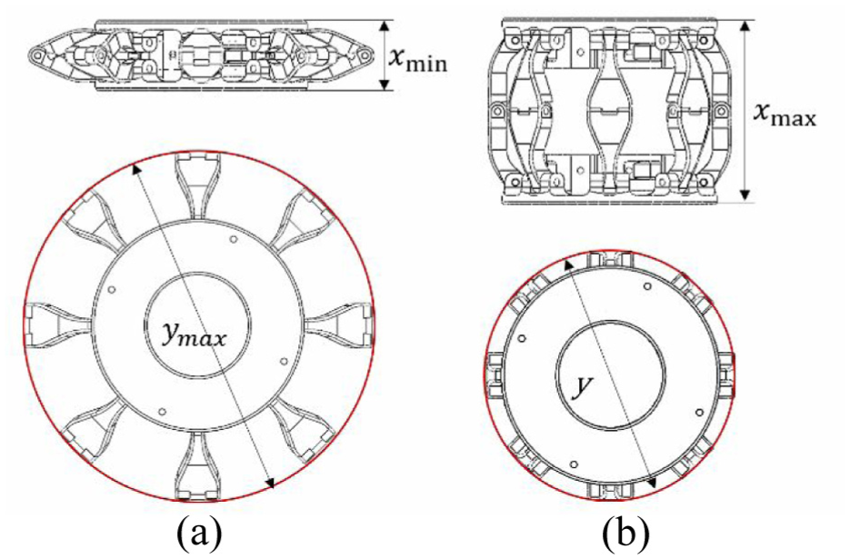
Configurations of Sarrus linkage module: (a) contraction configuration and (b) expansion configuration.
As shown in Figure 6, during the expansion and contraction movement of the Sarrus linkage module, if the linkages have equal lengths and one of the two main sliders is fixed while the other moves axially by a distance

where

Radial variation of Sarrus linkage module.
From equation (1), it can be seen that during the expansion and contraction movement of the Sarrus linkage module, the change in the radial dimension
To enable the robot to move continuously like an earthworm, multiple Sarrus linkage modules need to be connected in series and driven sequentially to create a continuous peristaltic wave. This allows the robot to move forward in the same way as an earthworm. Based on the movement mechanism of the earthworm, and to increase the radial contact force between the peristaltic robot and the soil, this study selects four Sarrus linkage modules in series to form the peristaltic mechanism of the robot for design and analysis.
Within one cycle, two Sarrus linkage modules are always in an axial contraction and radial expansion state, interacting with the surrounding soil to anchor the robot, while providing a reaction force for the advancement of the other two Sarrus linkage modules and the drilling mechanism. In this study, four Sarrus linkage modules are connected in series, expanding and contracting sequentially to achieve the desired peristaltic motion. The sequence of expansion and contraction for the four modules is shown in Figure 7. After completing one full cycle, the robot advances a distance

Expansion and contraction sequence of Sarrus linkage modules.
Transmission mechanism
To achieve the expansion and contraction motion of four sequentially connected Sarrus linkage modules under a single drive source, as illustrated in Figure 7, this study designs a cylindrical cam transmission mechanism. The cylindrical cam converts the rotational motion of the motor into the linear motion of the Sarrus linkage modules, driving the movable ring slider of each module to expand and contract along the axial direction.
Based on the characteristics of cylindrical cam transmission, this study selects a geometrically closed-groove cam mechanism, as illustrated in Figure 8. A cam roller follower, installed in the movable ring slider, engages with the cam groove, ensuring continuous contact between the cam and the follower. As the cylindrical cam rotates, the roller follower moves along the cam groove, driving the ring slider in linear motion. This motion controls the expansion and contraction of the Sarrus linkage modules.

Schematic diagram of groove cam mechanism.
Additionally, to enable the cylindrical cam to flexibly transmit torque during passive steering, this study segments the cylindrical cam into multiple sections, which are connected using flexible shafts. This design ensures that even when the robot bends, it can still effectively transmit rotational motion and torque. The next section will first discuss the design of the cylindrical cam groove profile to achieve the sequential motion planning of the connected Sarrus linkage modules.
Design of the cylindrical cam groove profile
The proposed robot consists of four Sarrus linkage modules and five ring sliders, as illustrated in Figure 9(a). Each ring slider, involving the cam roller follower, corresponds to a groove profile curve. By unrolling the cam profile along the circumference, as shown in Figure 9(b), the groove profile curves can be analyzed and designed.
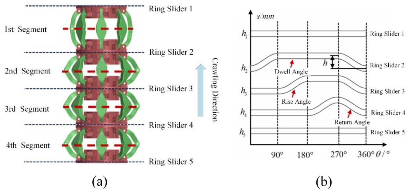
Relationship between each ring slider and cam rotation angle: (a) Four-Sarrus-Linkage and Five-Ring-Slider Robot and (b) Unrolled Cam Profile.
In Figure 9(b), the horizontal straight segments represent the dwell angles, during which the ring slider has no relative axial displacement with respect to the cam. The upward-sloping curves indicate the rise angles, where the ring slider moves forward along the cam axis. The downward-sloping curves represent the return angles, where the ring slider moves backward along the cam axis.
The profile curves corresponding to ring sliders 1 and 5 unfold into straight lines along the circumference, indicating that they exhibit no axial displacement. In contrast, the profile curves of ring sliders 2, 3, and 4 consist of three segments: a rise phase, a return phase, and a dwell phase, differing only in their phase shifts.
Taking ring slider 4 as an example, the groove profile curve is designed as follows:
1. Determining the stroke
2. Defining the rise angle
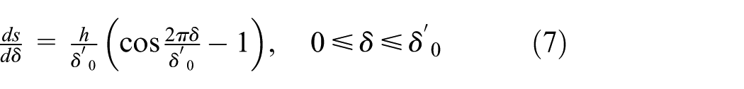
3. Selecting the cam motion profile: The cylindrical cam in this study functions as the transmission component of the peristaltic mechanism, linking multiple Sarrus linkage modules. The axial expansion and contraction distance of each Sarrus linkage module is governed by the motion of the follower. To ensure smooth movement, the follower motion follows a sinusoidal acceleration motion law (also known as a cycloidal motion law), as illustrated in Figure 10. The advantage of the cycloidal motion law is that the acceleration and velocity at both the start and end points of the follower’s motion transition smoothly, preventing rigid impacts.

Follower motion following the sinusoidal acceleration law: (a–c) variation of follower displacement
The motion equation for the cycloidal motion law during the rise phase is given by equation (2).

where
The motion equation for the cycloidal motion law during the return phase is given by equation (3).

where
4. Converting the selected angle into length: the relationship between the cam profile unrolling length

5. Determining the cylindrical cam radius

By differentiating the follower displacement

By differentiating the follower displacement
Based on the relationship between the developed length

By combining equations (5), (6), and (8), the relationship between the pressure angle

Similarly, by combining equations (5), (7), and (8), the relationship between the pressure angle

Given that
6. Determining the cylindrical cam radius

where

Within the return angle range of

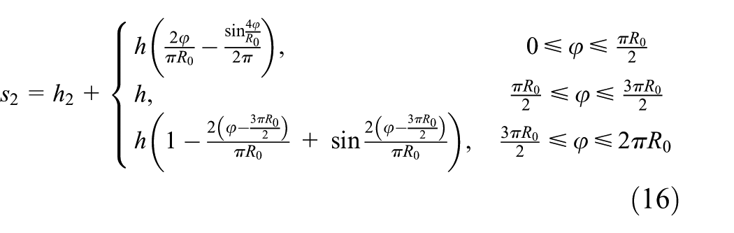
By combining equations (11)–(13), the cam profile curve

Following the method of the cam profile curve
The cam profile curve

The cam profile curve
The cam profile curve

The cam profile curve

For the design of the Sarrus linkage module, the lift stroke is set to

Cam groove profile curve corresponding to ring slider motion.
Optimization of the cylindrical cam
To ensure the smooth expansion and contraction of the peristaltic mechanism, the cylindrical cam requires an optimized design. During prototype validation, it was observed that when a single cam roller follower drives the ring slider along the cylindrical cam’s profile, significant motion resistance occurs. At specific cam rotation angles, the ring slider experiences intermittent jamming. This phenomenon stems from the radial clearance between the slider and the cam cylinder, which induces eccentric loading on the roller follower. Consequently, a dynamic moment is created about the slider’s axis, causing misalignment-induced oscillations during translational motion. This parasitic movement increases Coulomb friction at the slider-cam interface and generates stick-slip effects, ultimately impeding relative motion.
To minimize friction during the actuation of the ring slider along the cam interface, this study proposes a dual-roller follower configuration for each slider unit, as illustrated in Figure 12(a). To ensure an even distribution of forces between the two roller followers, the phase angle between the two cam groove profiles for each ring slider is set to 180°. This design allows the ring slider to move more smoothly along the cylindrical cam, significantly reducing resistance and improving overall system efficiency. The corresponding cam groove profiles for the ring sliders with dual cam roller followers are depicted in Figure 12(b).
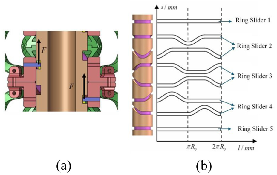
Dual-roller follower configuration and corresponding cam groove profiles for slider units: (a) dual-roller follower configuration for each slider unit and (b) corresponding cam groove profiles.
The optimized design, which utilizes two cam roller followers to drive a single ring slider, effectively reduces friction between the Sarrus linkage module and the cylindrical cam, thereby enhancing the cam’s transmission efficiency.
Design of flexible transmission mechanism under bending
To enable the bionic earthworm-like peristaltic robot to adjust its direction and avoid obstacles during excavation, this study divides the cylindrical cam into multiple segments. The cylindrical cams corresponding to ring sliders 2–4 are duplicated, and each section is connected using a steel wire flexible shaft, as shown in Figure 13.

Multi-segment cylindrical cam with flexible shaft connection.
The steel wire flexible shaft is a low-rigidity and highly elastic shaft that can bend freely, making it suitable for connecting multiple rotating axes that are not aligned in a straight line. This design effectively transmits rotational motion and torque. It enables the cylindrical cam to bend and transmit torque during passive steering of the robot.
Additionally, to ensure the stable transmission of axial force in the robot, a compression spring is introduced. The compression spring is connected between two segments of the cylindrical cam through a spring bracket, maintaining a preloaded state during the connection. The combined force from the spring and the partial elastic force provided by the steel wire flexible shaft meets the axial force transmission requirements for both the drilling bit and the Sarrus linkage modules of the peristaltic mechanism.
The external support of the transmission system is designed using a bellows. The bellows consists of a cylindrical thin-walled structure with multiple transverse corrugations, which provides elasticity. When subjected to bending moments, the bellows can undergo corresponding bending deformations. The bellows is hollow inside, with a steel wire flexible shaft passing through it to transmit torque. This study uses three sections of bellows connected in series to link the four Sarrus linkage modules, as shown in Figure 14.

Flexible transmission mechanism.
Although this design reduces the phase variability between modules and limits the system’s degrees of freedom, it offers advantages such as a reduced number of actuators, lower system complexity and weight, and improved stability. The bending capabilities of the bellows and the flexible steel wire shaft allow the robot to achieve passive steering and flexible transmission under bending, enabling it to avoid obstacles and continue moving forward. This design realizes “sequential drive and transmission under bending” using a single motor to actuate the multiple Sarrus linkage modules and the drilling mechanism.
Simulation and prototype experimentation
Static analysis
To ensure that all components of the peristaltic robot meet design requirements, a static simulation analysis is conducted on the core components of the robot’s peristaltic mechanism. This paper first analyzes the static behavior of the Sarrus linkage module. The module’s components are made of alloy steel, with an elastic modulus of

Static analysis of Sarrus linkage module: (a) deformation diagram and (b) stress diagram.
From the analysis results in Figure 15(a), it can be observed that the overall deformation of the designed Sarrus linkage module is approximately
Similarly, a static analysis is performed on other core components of the biomimetic peristaltic robot. As the primary transmission element of the peristaltic mechanism, the cylindrical cam plays a crucial role in transmitting torque from the motor. Hence, a static analysis is necessary for this component. Figure 16 presents the deformation and stress analysis results of the cylindrical cam under torque loading. The analysis confirms that the structural design of the cylindrical cam meets the static requirements.
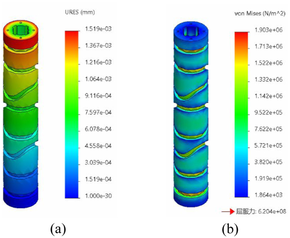
Static analysis of the cylindrical cam: (a) deformation diagram and (b) stress diagram.
Prototype development
The overall view of the experimental prototype of the designed peristaltic robot is shown in Figure 17. The prototype has a length of approximately 840 mm, a diameter of about 126 mm, and a weight of around 2.3 kg. The host computer controls the movement of the robot via the STM32 control board. Meanwhile, the STM32 board communicates through a serial interface to record the variation of motor torque over time. A laser distance sensor is fixed in place to measure the robot’s displacement during peristaltic motion, allowing for the calculation of its moving speed.

Robot prototype.
Figure 18 illustrates the core component of the peristaltic tunneling robot—the Sarrus linkage module. It consists of two movable ring sliders and eight pairs of linkages, which are assembled using screws. Most parts of the experimental prototype are manufactured using 3D printing technology with materials such as PLA and ABS.

Prototype of Sarrus linkage module.
Figure 19 presents the physical cylindrical cam. A single cylindrical cam is divided into four segments, each corresponding to one of the four Sarrus linkage modules in the peristaltic mechanism. A flexible steel shaft with a diameter of 14 mm is used to connect the multiple cam segments, as shown in Figure 19.

Prototype of cylindrical cam.
The four Sarrus linkage modules are connected by three sections of bellow, each with a diameter of 50 mm, an outer diameter of 65 mm, and a length of 100 mm. Compression springs are used to transmit the axial force between adjacent cylindrical cam segments during bending motion, as shown in Figure 20.
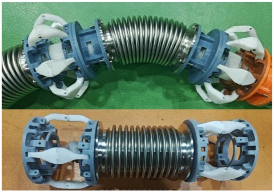
Prototype of flexible transmission mechanism.
The drilling mechanism is located at the front end of the robot, with the prototype manufactured using 3D printing technology from ABS material. The drill bit is connected to one end of the cylindrical cam via a coupling, allowing for synchronized rotation. Additionally, the drill bit is connected to the Sarrus linkage module through a thrust bearing, enabling relative rotational movement (Figure 21).

Prototype of drilling mechanism.
Prototype testing
Movement speed testing experiment
To evaluate the peristaltic forward motion performance of the robot, this section conducts tests to measure the robot’s movement speed on the ground. During the experiment, a laser distance sensor fixed on the ground is employed to track the robot’s forward displacement over time. An STM32 control board communicates via a serial port to record the motor torque variation over time. In the experiment, the motor operates at a constant angular velocity of ω = 2 rad/s.
During the test, the robot successfully crawled forward on the ground, as shown in Figure 22. The data collected from the motor torque variation over time reveals that the maximum torque is approximately 2.8 N m, and the minimum torque is 0.4 N m, exhibiting periodic fluctuations, as shown in Figure 23. The torque trend indicates that the cylindrical cam transmission works effectively during the robot’s crawling motion, further validating the feasibility of using the cylindrical cam as the driving unit in the peristaltic mechanism.
Prototype ground movement speed experiment.

Motor torque versus time during ground movement speed experiment.
The data collected from the laser distance sensor can be used to plot the displacement-time curve. The speed of the robot’s forward crawling on the ground is approximately 2.31 mm/s. As shown in Figure 24, the measurement results indicate that the robot moves the same distance during each cycle of its periodic crawling motion. This observation is consistent with the timing sequence planned for each cycle in this study.

Robot displacement versus time during ground movement speed experiment.
Flexible transmission mechanism test
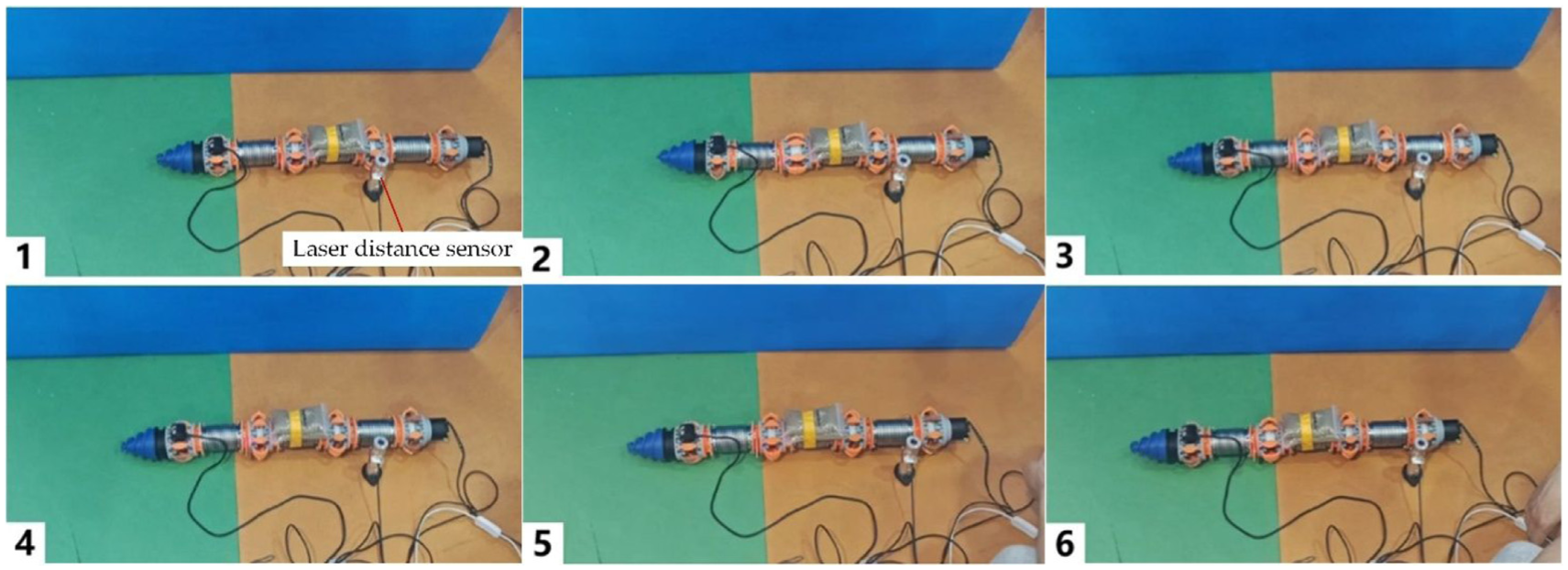
To evaluate the robot’s passive obstacle avoidance and passive steering capabilities, a transparent cylindrical object is used as an obstacle, as shown in Figure 25. The obstacle has a diameter of 160 mm, which is larger than the robot’s maximum diameter of 126 mm. Figure 25(1) illustrates the initial state of the experiment. Figures 25(2) and (3) show the robot engaging in passive steering upon contact with the obstacle. Figures 25(4), (5), and (6) depict the robot completing the steering maneuver and continuing forward. The results confirm that the robot successfully avoids the obstacle and maintains forward movement. This experiment verifies that the flexible transmission mechanism meets the required steering performance for passive obstacle avoidance and demonstrates that it functions properly during the passive steering process.

Flexible transmission test experiment.
This study further evaluates the prototype’s maximum bending angle. The robot’s head and tail are fixed with two clamps. The angle between the clamps, measured with an angular measurement tool, defines the robot’s bending angle, as shown in Figure 26. By varying this angle, the motor driving torques corresponding to different bending angles are measured. The results are shown in Figure 27.

Bending angle measurement for prototype.
Figure 27 indicates that the driving torque increases with the bending angle. When the driving torque reaches a certain threshold, the robot encounters difficulty in movement. The corresponding bending angle is defined as the maximum bending angle, measured to be approximately

Driving torque versus bending angle.
Burrowing experiment in simulated sandy soil
In this study, plastic pellets are used to simulate the sandy soil environment. The motor rotates at a constant angular velocity of

Particle environment drilling experiment.
In the experiment, the prototype tunnels downward through the pellets until it is completely buried. The motor continues to rotate normally during this process. The motor torque values recorded at this stage are shown in Figure 29. From the collected motor torque data, it can be observed that the maximum torque during the downward tunneling process is 2.8 N m, while the minimum torque is 0.26 N m.

Motor torque versus time in burrowing experiment.
Conclusions
This paper presents a novel peristaltic robot comprising a drilling mechanism, a peristaltic mechanism, and a transmission mechanism. A multi-segment, series-connected Sarrus linkage module is designed as the peristaltic mechanism. By undergoing radial and axial contraction and expansion, this mechanism mimics the contraction and relaxation functions of an earthworm’s circular and longitudinal muscles, enabling the robot to crawl forward. To achieve sequential motion of the Sarrus linkage modules using a single driving source, a cylindrical cam transmission mechanism is designed based on the calculated cam groove profile curve.
To minimize sliding resistance in the ring sliders of the Sarrus linkage modules and enhance the cam’s mechanical performance, an optimization scheme is proposed. This scheme incorporates a dual-roller follower configuration for each slider unit, along with the corresponding cam profile curve.
For passive steering, the cylindrical cam is divided into multiple segments connected by a flexible shaft, bellows, and compression springs. This design enables the robot to bend and steer passively while maintaining effective rotational motion and torque transmission during bending.
Static analysis of key components is conducted using simulation software to verify the rationality and reliability of the design. Finally, prototype experiments validate the robot’s crawling, passive steering, and tunneling capabilities.
Footnotes
Handling Editor: Lianjun Wu
Author contributions
All authors contributed to the study of a biomimetic earthworm-like peristaltic robot mechanism. DJZ wrote the manuscript and conducted experiments; BJQ designed and analyzed the mechanisms; BL provided the mechanism analysis; and YY contributed to the conceptualization, and supervision.
Funding
The authors disclosed receipt of the following financial support for the research, authorship, and/or publication of this article: This research was supported by the National Natural Science Foundation of China under Grant 52475023, and Natural Science Foundation of Shanghai Municipality under Grants 24ZR1424300, 23DZ2229032.
Declaration of conflicting interests
The authors declared no potential conflicts of interest with respect to the research, authorship, and/or publication of this article.
Data availability statement
All data generated or analyzed during this study are included in this published article.