
Abstract
This study presents the development and experimental application of a high-strength fiber cementitious composite (HSFCC) reinforced with steel fibers, aiming to improve structural efficiency in reinforced concrete beam members. The HSFCC exhibited excellent workability with a slump flow over 700 mm, compressive strength of 133.18 MPa, tensile strength of 10.97 MPa (strain 0.34%), and shear strength of 34.07 MPa. To verify the applicability, simply supported beam tests were conducted on non-rectangular reinforced HSFCC specimens designed to enhance bending and shear performance. Compared to conventional concrete beams, HSFCC beams achieved up to 75% higher bending capacity and 6.49 times higher shear capacity even without stirrups. These results highlight the structural advantages of HSFCC in minimizing reinforcement and cross-sectional area while maintaining high performance, suggesting its potential for application in high-rise or long-span buildings.
Keywords
Introduction
In the 21st century, buildings have become taller and larger accompanying with new launching of urban projects, especially in Middle East and Asia. The structural members in high-rise buildings require a large scale of the cross section accompanying with a long span in beam and column structural members.1,2 On the other hand, concrete has been most commonly used as one of structural materials in building structures. The demands of high-strength and high-performance characteristics of concrete are gradually rising according with the increase of high-rise building constructions. However, concrete has some disadvantages in its brittle fracture behavior due to the crack localization in tension because its tensile strength and deformation capacities are very poor to compare with the compressive strength and de fiber-reinforced beam formation capacities. 3 As the compressive strength increases, the tensile strength also increases, but the tensile strain performance is little effect on change.
In order to overcome the weakness of concrete in tension, high-performance fiber cementitious composites incorporating synthetic or steel fibers in the cementitious binder matrix had been actively attempted to develop by several researchers.4–10 Most of the high-performance fiber cement-based composite materials had a compressive strength of less than 60–80 MPa, as many studies had been reported.11–15 With the growing demand for high compressive strength of 100 MPa or more, many researchers have attempted to develop high-performance fiber cementitious composites and high-strength concrete.16–20 Concrete has also an advantage of being able to be freely creating shapes as long as the formwork is made, but most of structural columns or beams in concrete buildings are made with regular shapes as square and rectangular cross-sections. The reason is not only for the construction practice and structural design but also for the planning in the efficient design of plane space.21–23
Despite significant advancements in fiber-reinforced cementitious composites such as Engineered Cementitious Composites (ECC), Strain-Hardening Cementitious Composites (SHCC), and Ultra-High Performance Concrete (UHPC), these materials still present limitations. 24 ECC and SHCC exhibit excellent tensile strain capacity but typically show compressive strength below 60–80 MPa. UHPC achieves ultra-high compressive strength but suffers from limited ductility and high material and curing costs. 25 This study addresses the gap between these materials by developing a novel HSFCC that integrates both high compressive strength (over 130 MPa) and ductile tensile performance (strain ~0.34%). While previous studies have rarely applied such composites to non-rectangular structural elements, this work uniquely applies HSFCC to aesthetically and structurally optimized beam sections, thus contributing both to material development and application design. 26
In the current research, a high strength fiber cementitious composite (HSFCC) has been newly manufactured to have high compressive strength as well as high ductile tensile characteristics. To compare with normal concrete, it is intended that the HSFCC is suitable to use in design of bending and shear dominated building structural members accompanying with minimizations of longitudinal and transverse reinforcing steel bars as well as the cross-sectional area in beams and columns. In order to apply HSFCC in beams, non-rectangular cross-sections of reinforced HSFCC beams are newly designed and a series of simply supported beam tests are carried out. From experiments, bending and shear performances of the beams will be evaluated to compare with reinforced concrete beams varying with different amounts of longitudinal and transverse reinforcing steel bars. The contents of this research were summarized as follows; mixing and manufacturing methods, mechanical tests, and characteristics of HSFCC in Section “Materials and mechanical characteristics of HSFCC,” the design of beam cross-section, bending and shear dominated experimental methods, and manufacturing processes of reinforced HSFCC beams in Section “Experiments of reinforced HSFCC beams,” performances in bending and shear dominated beam loading tests and comparisons of HSFCC beams with conventional RC beams in section “Loading test results of beams and discussions,” and conclusions in the last section.
The major challenges addressed in this study include the difficulty in achieving both high compressive and ductile tensile behavior in a single cementitious material, and the lack of applications of such material in non-standard beam geometries. To overcome these, a balanced mix of zirconium silica, shrinkage-reducing agents, and hybrid steel fibers was optimized. The use of HSFCC in non-rectangular cross-section beams not only improves structural performance but also enhances material efficiency and design flexibility, which has rarely been achieved in previous studies.
Materials and mechanical characteristics of HSFCC
Materials
Ultra-high-strength concrete (UHPC) with compressive strength exceeding 180 MPa is difficult to place in on-site construction and entails high manufacturing and curing costs. Therefore, concrete with a compressive strength of 120–140 MPa is considered more reasonable for building structural members compared with UHPC, which has been widely applied in bridge and highway structures. For applications of structural members in low-rise and medium height buildings, this study intends to mix and manufacture a high-strength steel fiber cementitious composites (HSFCC) considering with the targeted compressive strength of 120–140 MPa.
The mixing composition of the HSFCC used in this study is shown in Table 1. As shown in the table, the binder was mainly mixed with ordinary Portland cement, zirconium silica fume, filler, and expansion material. Zirconium silica fume was used with the Blaine fineness of 80,000 cm2/g or more, and the filler was taken as an average particle size of 10 µm and a SiO2 component of 99% or more. Silica sand with a diameter of 0.5 mm or less was used as the fine aggregate. The steel fiber used in the HSFCC, as presented in Figure 1, had a modulus of elasticity of 200 GPa and a tensile strength of 2700 MPa. The selection of zirconium silica fume, shrinkage-reducing agent, and steel fibers was based on their contributions to the mechanical and rheological properties of the composite. Zirconium silica fume improves the packing density and strength due to its high pozzolanic activity. The shrinkage-reducing agent limits microcrack formation and long-term shrinkage. Steel fibers with lengths of 16 and 20 mm were combined at a ratio of 1:2 to balance crack-bridging capacity and fiber dispersion, thereby enhancing both tensile and shear performance.
Mixing proportion of HSFCC and normal concrete.

Super-plasticizer.
Shrinkage reducing agent.
Defoamer.

Measurement of a length of steel fiber.
The dimensions and the properties of steel fibers are shown in Table 2. The diameter of the steel fibers was 0.2 mm, and the lengths of 16 and 20 mm were mixed at a ratio of 1:2, respectively. In the mixing of the HSFCC, a water-to-binder ratio of 15.6% was used, and a polycarboxylic acid-based high-performance water reducing agent with 30% solid content was added to ensure homogeneous dispersion and material strength. A defoamer was used to minimize entrapped air during mixing, and a liquid-type shrinkage reducing agent was added to prevent early-age shrinkage of the matrix.
Properties of steel fibers.

The detailed stepwise mixing procedure of HSFCC was as follows:
(1) Dry mixing of premixed binder (OPC, zirconium silica fume, filler, and expansion material) and silica sand for 10 min.
(2) Addition of water mixed with high-performance superplasticizer (SP), shrinkage reducer admixture (SRA), and defoamer, followed by mixing for 8 min.
(3) Gradual addition of steel fibers (16 and 20 mm at a 1:2 ratio) and mixing for 2 min.
(4) Final low-speed mixing for 1 min to control air content.
After mixing, specimens were cast into molds, demolded after 24 h, and water-cured at 21°C–25°C until testing age (14 and 28 days). Figure 2 illustrates this step-by-step process. For comparison, the mix proportion of normal concrete is also shown in Table 1, in which the binder consisted of only ordinary Portland cement. Coarse aggregates with a maximum size of 25 mm and fine aggregates of 5 mm or less were used along with small amounts of superplasticizer and Air-Entraining (AE) agent. These processing parameters were determined from preliminary trial mixes and are consistent with procedures reported in recent studies on UHPC and fiber-reinforced mortars.27,28 The mixing was performed using a laboratory concrete pan mixer operating at a maximum speed of 50 revolutions per minute (rpm). In addition to the mechanistic rationale, the selection of zirconium silica, SRA, and hybrid fibers was supported by recent studies reporting improved shrinkage reduction, durability, and crack-bridging efficiency compared with conventional SCMs or single-length fibers.29,30

Mixing of HSFCC: (a) dry mixing, (b) add water and admixture, (c) fiber mixing, and (d) finish mixing.
Previous studies have also reported that fiber-reinforced cementitious composites with low water–binder ratios and dense matrices generally show reduced shrinkage and creep, enhanced resistance to freeze–thaw cycles and chloride ingress, and extended fatigue life. These findings suggest that HSFCC beams can be expected to provide favorable durability performance.8,31,32
Material and mechanical properties of HSFCC
As a result of the slump flow test on fresh HSFCC, 33 soon after finishing of mixing, the measured slump flow obtained from three samples of fresh HSFCC showed over 700 mm for all samples, as presented in Figure 3. It was shown that the condition of the fresh HSFCC was appropriate to minimize material separations and fiber ball phenomenon during mixing of the material.

Slump-flow test: (a) measurement of slump-flow and (b) slump-flow of 735 mm.
Mechanical properties of the hardened HSFCC were evaluated through uniaxial compression, direct tension, and shear tests. All specimens were demolded after 24 h and water-cured at 21°C–25°C until testing. 34 The uniaxial compressive test was conducted according to ASTM C39 using cylindrical specimens with a diameter of 100 mm and a height of 200 mm (Figure 4). 35 Compressive strengths were measured at 14 and 28 days for HSFCC, while normal concrete specimens were tested only at 28 days. As shown in Table 3 and Figure 5, twelve HSFCC specimens and seven normal concrete specimens were tested. The average compressive strength of HSFCC was 126.88 MPa at 14 days and 133.18 MPa at 28 days, indicating that approximately 95% of the 28-day strength had been achieved by day 14. Figure 4 shows the crack and failure patterns observed in both HSFCC and normal concrete specimens. The 28-day strength of HSFCC was approximately 3.9 times higher than that of normal concrete mixed with a water-binder ratio of 44%.

Failure of compressive specimens: (a) HSFCC and (b) normal concrete.
Measured compressive strength of specimens.


Test results of compressive strength for HSFCC and normal concrete.
For direct tensile and shear tests, five specimens were fabricated for each HSFCC test using custom-designed molds. Dog-bone-shaped specimens were prepared for the tensile test, and specimens for the shear test were cast according to the dimensions shown in Figure 9(b). For the shear test, four specimens of the Vectran fiber-reinforced composite and one specimen of normal concrete were used.
The direct tensile test was performed using a 100 kN universal tensile testing machine. As illustrated in Figure 6, the dog-bone specimen was precisely fitted into steel Zigs that matched the specimen’s geometry, preventing slippage during loading. The gripping sections were designed with a larger cross-sectional area than the gauge region to ensure that tensile cracks occurred in the measurement zone.

Uniaxial tensile test: (a) test setup and (b) specimen geometry.
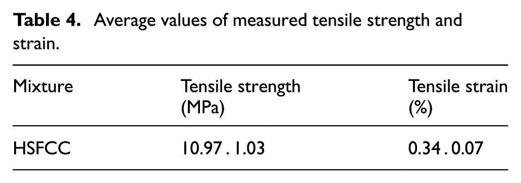
Tensile loading was applied using displacement control at a rate of 0.2 mm/min, which was adopted in accordance with ASTM C1609 36 and the JSCE HPFRCC 37 guidelines to ensure stable crack propagation in fiber-reinforced composites. A load cell measured the tensile force, and tensile strain was captured using two linear variable differential transformers (LVDTs) over a 150 mm gauge length. The tensile stress–strain relationships are shown in Figure 7. The tensile strength ranged from 9.67 to 12.30 MPa, and the corresponding strains ranged from 0.25% to 0.44% (Table 4). Multiple fine cracks were observed after initial cracking, attributed to the bridging action of steel fibers. After reaching peak strength, specimens exhibited strain-softening behavior, as the stress gradually decreased with increasing strain. Failure modes and crack patterns are shown in Figure 8. 13

Uniaxial tensile test results of HSFCC.
Average values of measured tensile strength and strain.

Crack patterns of HSFCC specimens: (a) HSFCC-4 and (b) HSFCC-5.
The direct shear test used a specially designed device (Figure 9) to apply load to both ends of the specimen, inducing shear stress in the central 80 mm × 60 mm area with notches on both sides. As noted above, five HSFCC specimens, four Vectran specimens, and one normal concrete specimen were tested, and their shear strength was compared. Vectran fibers had a tensile strength of 3200 MPa, with a length of 12 mm and a volume fraction of 1.5% (Figure 10).

Direct shear test: (a) test setup and (b) specimen geometry.
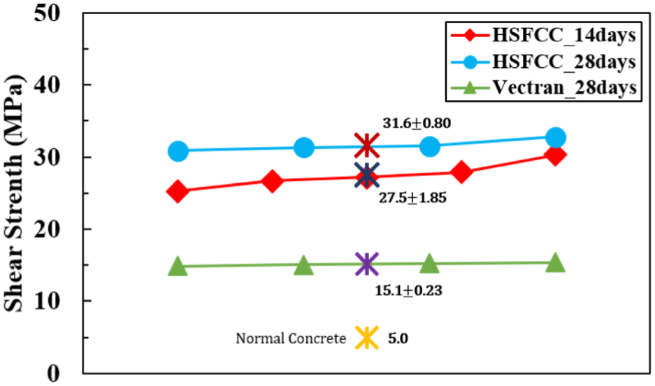
Results of direct shear test.
HSFCC shear strength was measured at 27.46 MPa (14 days) and 31.62 MPa (28 days), with a 15.15% increase over time. In contrast, normal concrete recorded 5.04 MPa and Vectran fiber-reinforced specimens 15.14 MPa at 28 days (Table 5). Thus, HSFCC demonstrated approximately 6.27 times higher shear strength than normal concrete and 2.08 times higher than Vectran-mixed specimens. As shown in Figure 11, steel fiber bridging significantly enhanced crack control and shear resistance, allowing specimens to sustain loads until sudden failure at peak stress.
Measured average shear strength for specimens.


Failure of shear specimens: (a) 14 days and (b) 28 days.
Experiments of reinforced HSFCC beams
Design and manufacture of beams
To investigate the bending and shear behavior of HSFCC beams, a series of reinforced specimens with non-rectangular cross-sections were designed and fabricated. As shown in Figure 12, from an aesthetic point of view, the cross-section of a non-rectangular beam was proposed by following a shape of traditional Korean ceramic pottery. This cross-sectional shape was optimized based on mechanical reasoning: the upper compression zone was enlarged to fully utilize the superior compressive strength of HSFCC, whereas the lower tension zone was minimized and primarily reinforced with steel bars that provide sufficient tensile capacity. This strategy leads to enhanced flexural capacity while minimizing the volume of expensive HSFCC, thereby achieving high structural performance with improved material efficiency. In addition, this distinctive form reduces the risk of brittle failure by distributing compressive stresses over a larger area. The lower portion of HSFCC in the cross-section will sustain tensile stresses along with tensile reinforcing steel bars. As shown in the Figure 12, for specimens of reinforced non-rectangular HSFCC beams, the upper width of the cross-section is 200 mm, the lower width is 130 mm, the height of the cross-section is 300 mm, the total length of the beam is 2100 mm, and the net span is 1800 mm.

Cross-section of non-rectangular beam: (a) a shape of Korean pottery and (b) a cross-sectional design of beam.
The longitudinal reinforcement configuration for each beam is detailed in Table 6. For all specimens, six tensile bars were placed at the bottom: either 6-D19 or 6-D22 depending on the specimen type. In addition, four compression bars of D10 were consistently arranged at the top for all beams. Stirrups were arranged either throughout the span or locally to induce bending or shear failure depending on the experimental objective. These reinforcement details, including bar sizes, stirrup spacing, and loading positions, are clearly illustrated in Figures 12 and 13.
Details of the non-rectangular beams.


Experimental method of structural beams: (a) bending failure beam, (b) shear failure beam, and (c) 3D of beam.
The reinforcement ratios were designed in accordance with the minimum and maximum requirements of ACI 318, 38 and compression bars were included to ensure section stability. For flexure-dominated specimens, the shear span-to-depth ratio (a/d) was set greater than 2.5, while for shear-dominated specimens it was less than 2.5, following established design principles to control the failure mode. Thus, the reinforcement and support conditions were determined on a rational code-based basis rather than arbitrarily.
All beam specimens are descripted in Table 6 with details of reinforcing steel bars as well as the compressive strength of HSFCC and normal concrete. For comparative studies of experiments, specimens of reinforced concrete beams, RC-B1, RC-B2, and RC-S1, were manufactured with the same cross-section as a non-rectangular shape. Specimens of HSFCC-B1, HSFCC-B2, HSFCC-S1, and HSFCC-S2 are reinforced non-rectangular HSFCC beams with different details of reinforcing steel bars. For all beam specimens, there are two types in the beam failure, a type in the bending failure beam, specimens of RC-B1, RC-B2, HSFCC-B1, and HSFCC-B2, and a type in the shear failure beam, specimens of RC-S1, RC-S2, HSFCC-S1, and HSFCC-S2. For bending failure beams, as shown in Figure 13, a transversely concentrated load is applied in the mid-span of the beam and stirrups are arranged with a spacing of 60 mm to ensure final bending failure before reaching shear failure. For shear failure beams, a reinforced concrete beam of RC-S1 was manufactured without stirrups, and reinforced HSFCC beams, HSFCC-S1 and HSFCC-S2, were manufactured with stirrups and without stirrups, respectively. In the case of HSFCC-S2, the stirrups were arranged with a spacing of 60 mm. For RC-S1 and HSFCC-S1, as shown in Figure 13(b), stirrups were placed with a spacing of 60 mm only at the loading point and support along the long span, thereby inducing a shear failure between the loading point and the support along the short span.
In order to facilitate placing of rebars as well as confining effect of concrete when placing transverse reinforcements on the cross section of the non-rectangular HSFCC beam, auxiliary two longitudinal steel bars of D10 were placed near the middle of the cross-section, as shown in Figure 12. The manufacturing process of non-uniform HSFCC beams was shown in Figure 14. Beams after casting of fresh HSFCC was wet-cured at 21°C–25°C for 28 days.

Manufacture and casting of HSFCC beam specimens: (a) form work, (b) assembling the bar, (c) mixing, (d) casting, (e) curing, and (f) removal of forms.
Experiments of beams
For a series of simply supported beam transverse loading tests, two types of 3-point loading were considered using a displacement control method on a 1000 kN capacity Universal Testing Machine (UTM) as shown in Figure 15. For the test method induced to a beam bending failure, a concentrated load was applied at the center of the beam at a pure span length of 1800 mm. For the test method induced to a beam shear failure, a concentrated load was applied at a distance of 650 mm from the left support in which the shear failure was occurred and there were no shear reinforcements. The transverse displacement of beams was measured by installing an LVDT with a maximum capacity of 100 mm at the loading position.

Loading setup of beams: (a) bending failure type, (b) shear failure type, (c) loading for bending failure, and (d) loading for shear failure.
Loading test results of beams and discussions
Loading tests of bending failure beams
For specimens of the bending failure beam, the transverse load-displacement and the bending moment-curvature responses at mid-span were measured as presented in Figure 16. The load and displacement responses at three points of loading stages, the initial cracking point, the yielding point of tensile bars, and the point of the maximum load, were also presented in Table 7. For a specimen of RC-B1 which had tensile reinforcements of 6-D19, initial cracks were occurred at a load of 31.66 kN, tensile steel bars were yielded at a load of 275.48 kN, and a displacement of 6.5 mm was measured at a maximum load of 299.86 kN. For a specimen of HSFCC-B1, the point of initial tensile cracks was measured at a load of 35.81 kN, a tensile steel bar was started to yield at a load of 393.13 kN, and a displacement of 9.1 mm was measured at a maximum load of 434.92 kN which was increased in the maximum load capacity by about 45% compared with a specimen of RC-B1. For a specimen of RC-B2 which had tensile reinforcements of 6-D22, cracks were initially taken place at a load of 39.47 kN, a tensile bar was yielded at a load of 313.45 kN, and a displacement of 6.2 mm was measured at a maximum load of 330.17 kN. For a specimen of HSFCC-B2, initial cracks were occurred at a load of 36.90 kN, a tensile steel bar was yielded at a load of 508.76 kN, and a maximum load of 577.40 kN was measured corresponding with a displacement of 5.8 mm, and the maximum load was increased about 75% compared with a specimen of RC-B2. It could be seen that specimens of HSFCC non-rectangular beams were efficient to improve bending capacities due to the characteristics of a high compressive strength as well as an excellent tensile strain behavior.

Responses of bending type failure beams: (a) load-displacement curve and (b) moment-curvature curve.
Experimental results of bending type failure beams.


Failure of bending type beams (unit: kN): (a) RC-B1, (b) RC-B2, (c) HSFCC-B1, and (d) HSFCC-B2.
The final failure patterns of specimens and crack patterns with occurring of cracks according to load levels were shown in Figure 17. In cases of RC beams, bending cracks with a maximum width of 0.1–0.12 mm occurred at a load level of the initial crack, but the maximum width of cracks was gradually extended to 0.16 mm at the yielding point of tensile reinforcing steel bars. After yielding of tensile bars shear cracks were increased and shear cracks remained with a maximum width of 0.22–0.24 mm near the maximum load. Exceeding the displacement at the maximum load, a single shear crack was expanded into the compression zone, leading to drastically increase in a crack width of above 0.5 mm and RC beams were reached failure. For HSFCC beams, after cracks were initiated, multiple cracks with a width of 0.03–0.05 mm occurred near the center before the tensile reinforcing steel bar reached to yield. After yielding, the number of cracks increased but crack widths were controlled to remain below 0.1 mm until the maximum load. Even after reaching the maximum load, HSFCC beams exhibited additional crack formations but sustain the width of crack. However, before reaching failure, widths of multiple cracks expanded beyond 0.5 mm and one crack was significantly opened and finally reach to failure. Figure 17 shows the crack propagation and final failure modes for the flexural specimens. In RC specimens, wider cracks formed at fewer locations and propagated diagonally after bar yielding. In contrast, HSFCC beams showed more distributed and finer cracks. The presence of both tensile (bottom) and compression (top) reinforcement helped to maintain section integrity, particularly in HSFCC beams where the multiple-cracking behavior contributed to improved ductility and energy absorption. As demonstrated in the direct tensile tests, the bridging action caused by fibers in HSFCC effectively contributed to the formation of multiple cracks and the control of crack widths during a series of bending tests of beams.
Loading tests of shear failure beams
For specimens of the shear failure beam, the transverse load-displacement curves at the concentrated loading point were measured as presented in Figure 18. The measured maximum loads and displacements as well as the maximum loads at a shear span were also presented in Table 8. For a reinforced concrete beam of RC-S1, there was no stirrups at a distance of 650 mm between the left support to the loading point in which the shear failure was occurred. As a result of the experiment, the beam was finally reached to failure by shear cracks at a displacement of 2.2 mm and the maximum load was measured to 80.34 kN. For a specimen of HSFCC-S1 where reinforcement details were same as a specimen of RC-S1 in longitudinal and transverse directions, the maximum load was reached up to 521.54 kN corresponding with a displacement of 10.3 mm and the failure was caused by shear cracks. For a specimen of HSFCC-S2 where stirrups were applied with a spacing of 60 mm, it was reached to bending failure caused by compressive crushing of HSFCC on the upper portion near the loading point at a displacement of 12.7 mm corresponding with a maximum load of 589.81 kN. The final failure patterns of shear failure beams were shown in Figure 19.

Measured transverse load and displacement results of shear type failure beams.
Maximum loads and corresponding displacements shear type failure beams.


Failure of shear type beams (unit: kN): (a) RC-S1, (b) HSFCC-S1, and (c) HSFCC-S2.
In a case of RC beam, a shear crack initiated near the support at a load of 23.33 kN and a crack width was below 0.1 mm. As increasing the load, new formations of cracks weren’t evident but the maximum width of crack gradually extended above 0.5 at a load level of 65.7 kN. Without yielding of tensile reinforcing steel bars, the opening of the shear crack ultimately led to shear failure with a crack width of above 6.0 mm. For cases of HSFCC beams, similar with beams of the bending failure test, multiple cracks with a maximum width of ranging from 0.03 to 0.05 mm were observed at a load level of the initial crack and the maximum width of cracks was sustained until the yielding of tensile reinforcing steel bars, but the number of multiple cracks was increased. In cases of HSFCC beams, the maximum crack width remained below 0.3 mm until the maximum load reached. In the specimen of HSFCC-S1, which had no stirrups, the failure finally occurred soon after the widely opening of shear cracks with a width of above 7.0 mm, and in the specimen of HSFCC-S2, which had stirrups, the failure occurred by bending cracks with a maximum crack width expanded beyond 5.0 mm.
As illustrated in Figure 19, shear failure patterns were influenced by stirrup placement and internal reinforcement. In HSFCC-S1 (no stirrups), sudden diagonal shear cracking led to brittle failure, whereas HSFCC-S2 (with stirrups) showed more gradual damage progression. The consistent presence of top and bottom longitudinal reinforcement helped delay crack widening and enhanced post-peak behavior.
From a series of experiments on specimens of a direct shear strength as shown in the previous chapters, the average shear strength of HSFCC was about 6.27 times higher than that of concrete. From a series of experiments on specimens of the shear failure beam, the HSFCC beam of HSFCC-S1 had about 74% higher in the maximum load capacity than the concrete beam of RC-B1 which had stirrups and same amount of tensile reinforcing steel bars, and about 58% higher in the maximum load capacity than the concrete beam of RC-B2 which had same stirrups but an increased amount of tensile reinforcing bars. It was shown from experiments that non-rectangular HSFCC beams were effective to sustain cracks induced by shear and improve to resist a shear failure of the beam, thus transverse reinforcements could be minimized as well as the shear strength of beams could be improved in HSFCC beams.
Interpretation and discussion of experimental results
The experimental results revealed clear performance differences between HSFCC and RC beams. In bending tests, HSFCC beams (e.g. HSFCC-B1, HSFCC-B2) exhibited higher stiffness and peak loads than their RC counterparts. For example, HSFCC-B2 had a secant stiffness of 113.1 kN/mm compared to 61.5 kN/mm for RC-B2, and its maximum load was approximately 75% greater. These improvements are attributed to the high compressive strength and fiber bridging effect of HSFCC.
In terms of failure mode, HSFCC beams showed more distributed and finer cracks compared to RC beams, where fewer but wider cracks were observed. Crack widths in HSFCC beams remained under 0.1 mm until peak load, while RC beams exhibited cracks exceeding 0.2 mm at yielding. The delayed crack widening in HSFCC indicates enhanced durability and crack control capacity.
Ductility was also assessed through displacement at yield and failure, and energy absorption. In bending, HSFCC-B2 reached yielding at 4.5 mm and failed at 5.8 mm, while RC-B2 yielded at 5.1 mm and failed at 6.2 mm. Although the ultimate deformation was comparable, the load-bearing capacity and post-yield behavior of HSFCC were significantly superior. Furthermore, HSFCC beams absorbed more energy prior to failure due to gradual crack propagation and strain distribution enabled by steel fibers.
In shear, HSFCC-S1 (no stirrups) reached a maximum load of 521.54 kN versus 80.34 kN for RC-S1, which failed suddenly. The presence of hybrid fibers in HSFCC effectively suppressed diagonal shear crack growth and maintained residual strength after peak loading. Overall, the combination of higher strength, fine cracking, and enhanced ductility confirms the effectiveness of HSFCC in improving structural performance and durability.
Based on the measured responses, the HSFCC beams consistently showed greater toughness than their RC counterparts, with higher peak load, delayed crack widening, and more sustained post-peak resistance in both flexure- and shear-dominant cases. 39 The experimental results further suggest that the enhanced shear resistance of HSFCC beams is mainly governed by the fiber bridging effect and the high matrix strength, whereas the non-rectangular cross-section improved flexural performance by increasing the efficiency of the compression zone.
Comparison with previous studies and codes of practice
The mechanical and structural performance of HSFCC beams in this study shows significant improvements compared to both conventional reinforced concrete and high-performance fiber-reinforced cementitious composites (HPFRCCs) reported in previous literature. For example, previous studies on ECC and SHCC typically report compressive strengths of 60–80 MPa and tensile strains up to 2%, while the HSFCC in this study achieved a compressive strength of 133.2 MPa and a tensile strain of 0.34%. These results are consistent with the latest findings by Zhang et al. and Huang et al., who noted that optimized mix design and hybrid fiber use can considerably enhance the strength and ductility of cementitious composites.
For beam performance, the maximum flexural and shear capacities of HSFCC beams in this study exceeded those of conventional RC beams by 45%–75% and up to 6.5 times, respectively. According to design codes such as ACI 318 and EN 1992-1-1 (Eurocode 2), 40 the required amount of shear reinforcement in high-strength concrete beams may be reduced if the material demonstrates sufficient shear capacity and crack control. Our experimental results confirm that HSFCC beams, even without stirrups, can satisfy or exceed the minimum shear capacity required by codes, mainly due to the efficient crack-bridging effect of steel fibers.
In addition to ACI 318 and ACI 440 guidelines, the provisions of the CEB-FIB Model Code 2010 41 were also reviewed to evaluate the applicability of HSFCC. While ACI 440 imposes conservative limits on the shear contribution of fibers and still requires minimum transverse reinforcement, the CEB-FIB Model Code 2010 acknowledges fiber bridging as a contributor to shear resistance but emphasizes that it cannot fully substitute for other shear transfer mechanisms such as aggregate interlock and dowel action. This integrated perspective cautions against relying solely on fiber effects, particularly in high-strength concretes with low w/b ratios. In our experiments, HSFCC beams without stirrups (HSFCC-S1) exceeded the minimum shear strength requirements prescribed in both ACI 440 42 and CEB-FIB while maintaining multiple fine cracks with widths below 0.3 mm up to peak load. These results demonstrate that HSFCC not only complies with international code provisions but also addresses the serviceability concerns raised in these codes.
The experimental results were further compared with the allowable limits specified in international codes. According to ACI 318, the maximum crack width under service loads should not exceed 0.41 mm, and all measured values in HSFCC beams remained below this threshold until peak load. Moreover, the flexural and shear capacities of HSFCC beams exceeded the nominal strengths calculated by ACI 318 and CEB-FIB Model Code 2010. These comparisons confirm that the proposed HSFCC beams not only satisfy but also surpass the minimum requirements established by international codes.
The shear behavior of non-rectangular HSFCC beams can also be interpreted through analytical models. The strut-and-tie model explains the diagonal compression struts developed between the loading and support points, while the softened truss model considers tension stiffening and shear transfer through fiber bridging. These frameworks are consistent with the multiple fine diagonal cracks and enhanced shear resistance observed in the HSFCC beams without stirrups. In addition, recent analytical and FEM-based studies43–47 have demonstrated the ability of numerical and strut-and-tie modeling approaches to reproduce crack propagation, load–displacement responses, and shear transfer mechanisms in fiber-reinforced concretes. These references support that both analytical and FEM approaches are aligned with the experimental findings of HSFCC beams and provide useful directions for extending future research.
In summary, the superior performance of HSFCC beams found in this study, as well as the alignment with recent research and international codes, demonstrates that HSFCC is a promising material for high-performance structural applications demanding both strength and durability.
Conclusions
The aim of this study was to utilize the mechanical properties of high-strength fiber cementitious composite (HSFCC) and apply it to reinforced non-rectangular beams to achieve efficiency in bending and shear performance compared with conventional reinforced concrete beams. For this purpose, HSFCC was newly mixed and manufactured, and its mechanical and structural characteristics were evaluated through material property tests and a series of beam loading tests governed by bending and shear. The conclusions are as follows.
(1) HSFCC was mixed with a water–binder ratio of 15.6% and a steel fiber volume ratio of 1.5 vol.%. Despite this low ratio, it exhibited excellent workability with a slump flow of over 700 mm. At 28 days, the compressive strength reached 133 MPa, the tensile strength 10.97 MPa, and the tensile strain 0.34%, attributed to multiple microcracks formed by the fiber bridging effect. The direct shear strength was 31.6 MPa, which was about 6.3 times higher than that of normal concrete with 34 MPa compressive strength, confirming the outstanding matrix-fiber synergy of HSFCC.
(2) In beam bending tests, the maximum flexural failure load of HSFCC beams improved by approximately 45% and 75% for beams with 6-D19 and 6-D22 tensile reinforcement, respectively, compared with RC beams. In shear-dominant tests, the maximum shear failure load of HSFCC beams was about 6.5 times higher than RC beams without stirrups and 58%–74% higher in beams with stirrups. Fine crack development and bridging action allowed HSFCC beams to resist shear crack propagation effectively, thereby minimizing the need for transverse reinforcement while achieving high shear strength.
(3) Although the bending-type beam HSFCC-B2 had 35% more tensile reinforcement than the shear-type HSFCC-S2, the flexural moment capacities were similar (259.8 kN m vs 244.9 kN m, only 6.1% difference). This indicates that HSFCC enables structural efficiency by reducing required reinforcement and optimizing the tensile zone area. Moreover, toughness analysis showed that HSFCC beams consistently exhibited superior energy absorption and post-peak resistance compared with RC beams, confirming their enhanced ductility and crack control performance.
(4) The non-rectangular cross-section, inspired by Korean pottery forms, was designed to enlarge the compressive zone while minimizing the tensile zone to achieve material-efficient design, considering the higher cost of HSFCC. This design, combined with the superior mechanical properties of HSFCC, resulted in improved flexural and shear performance. Comparisons with international codes (ACI 318, CEB-FIB Model Code 2010, ACI 440) confirmed that HSFCC beams not only satisfy but exceed code requirements. Furthermore, interpretations using strut-and-tie and softened truss models were consistent with experimental results, highlighting that HSFCC provides a robust and code-compliant solution bridging the gap between ECC/SHCC and UHPC.
Footnotes
Handling Editor: Divyam Semwal
Funding
The author(s) disclosed receipt of the following financial support for the research, authorship, and/or publication of this article: This research was supported by Basic Science Research Program through the National Research Foundation of Korea (NRF) funded by the Ministry of Education Science and Technology (No.2023R1A2C2003175) and Chosun University (2022).
Declaration of conflicting interests
The authors declared no potential conflicts of interest with respect to the research, authorship, and/or publication of this article.