
Abstract
In this article, the enriched degree of freedom locking that can occur in a crack analysis with the extended finite element method is described. The discontinuous displacement field formulated by the enriched degree of freedom in the extended finite element method does not activate due to the enriched degree of freedom locking. Using the phantom node method, the occurrence of locking when two adjacent elements are simultaneously cracked in a loading step was verified. Two adjacent cracks can be determined to have developed simultaneously when an analysis model reveals a relatively uniform stress distribution on two adjacent elements. Numerical examples of a simply tensioned bar and a reinforced concrete beam are presented to demonstrate the erroneous analysis result due to the enriched degree of freedom locking. As a simple method to circumvent the enriched degree of freedom locking, the tensile strength of the neighboring elements was slightly increased in the numerical examples, and the effectiveness of the method was demonstrated. The proposed method is simple and easy for practicing engineers, and it can be easily applied to the three-dimensional crack propagation analysis.
Keywords
Introduction
The fracture or cracking of concrete is a significant nonlinear phenomenon that dominates the overall behavior of the structural members. Owing to the development of the finite element method, analysis methods for the cracking of concrete have been available since late 1960s. The discrete crack method, which was introduced by Ngo and Scordelis, 1 is aimed at predicting the initiation and propagation of dominant cracks by separating the pre-assumed cracks. One clear difficulty with such an approach is that the locations and orientations of the cracks are not known in advance. This drawback could be overcome by remeshing and refinement;2,3 however, these approaches are extremely complex and computationally expensive. The smeared crack method, which was proposed by Rashid, 4 is based on the assumption that the cracked concrete remains a continuum, and cracks are smeared out over the continuum. 5 However, such continuum models are mesh-dependent, given that a finer discretization leads to a decrease in the fracture energy. 6
Effective numerical methods to overcome the drawbacks of the early solutions to the crack problems were developed, such as mesh-free methods,7–9 boundary element methods,10,11 extended finite element methods (XFEMs),12,13 and generalized finite element methods.14,15 The mesh-free method can simplify the crack analysis by extending the crack surface, as it does not use a structured mesh, but a scattered set of nodal points in the domain of interest. The boundary element method was used to solve crack problems, as it only requires a boundary and crack surface. It is more efficient, particularly in solving mixed mode crack propagation problems, due to its efficiency in stress concentration modeling and cohesive crack growth. 16 The generalized finite element method incorporates the analytically known or numerically computed handbook functions to enhance the local and global accuracies of the computed solution. 17
The XFEM, which was proposed by Belytschko and Black, 18 uses a partition of unity method 19 and an enriched function to calculate the discontinuous displacement field, without complex numerical computations. In addition, level set methods are used to track the shape and propagation direction of the cracks, so that the shape of the cracks, independent of the size or shape of the element, can be visualized.20,21 Furthermore, given that the shape of the crack is expressed by a line or a surface inside the element, a remesh process due to crack propagation is not required. Therefore, the computation time due to crack propagation can be greatly reduced; furthermore, the method is effective in expressing multiple cracks. The XFEM describes the discontinuity of the displacement field using Heaviside functions and branch functions. The most important feature is that these enriched functions are multiplied by the shape functions of finite elements to easily describe the discontinuity. Thereafter, the cohesive crack method22–24 was developed to improve the description of crack tip characteristics without the calculation of complex branch functions and stress intensity factors. The phantom node method proposed by Song et al. 25 and Rabczuk et al. 26 contributed to simplifying the calculation of the discontinuity displacement field of a fully cracked element. This method simplifies the calculation by adding a phantom node or phantom degree of freedom (DOF) to implement the additional displacement.
The XFEM proposed for solving simple discontinuity problems was used for arbitrary three-dimensional cracks. 27 A study of cracks in various materials such as composite materials, 28 incompressible solids, 29 and metallic materials using a ductile damage model 30 was then carried out. In addition, the application range of cracked plates, including holes, inclusions, minor cracks, 31 and multiple cracks of reinforced concrete flexural members, 32 is gradually expanding. Therefore, XFEM was developed by several researchers and is currently used as a means of crack analysis in various fields. For example, Abaqus, which is a popular commercial finite element analysis program, has provided XFEM functionality since 2009. 33
However, problems with XFEM were observed in cases in which excessive stress is concentrated in the localized region, due to the unusual shape of the model, or the analysis of interaction behavior using two or more materials. In these cases, cracks occur simultaneously in adjacent elements, and the discontinuous behavior due to the cracks is not visible. This problem was reported by Yoo and Kim 34 and was termed enriched DOF locking. When the load is increased excessively in a loading step, or interactions between different materials such as concrete and reinforcements are applied to the model, adjacent elements can simultaneously satisfy the crack initiation criterion. Under these circumstances, the XFEM determines and displays the cracks in all the elements satisfying the failure criterion. However, although the cracks are determined and displayed by the XFEM, the cracks are not actually open, and the stresses of the cracked elements are not released. Figure 1(a) presents an example of the enriched DOF locking phenomenon in the flexural analysis of a reinforced concrete beam. Adjacent cracks developed at the center of beam and the cracks would not propagate upward. Although the beam with the enriched DOF locking shows cracks, it behaves like a linear elastic beam. Figure 1(b) presents the deformed shape of beam without the locking. The crack at the center initiated at the bottom of the beam and propagated upward.

Example of the enriched DOF locking in the XFEM analysis: (a) reinforced concrete beam with the enriched DOF locking and (b) reinforced concrete beam without the enriched DOF locking.
In this study, the characteristics of enriched DOF locking, where cracks occur simultaneously in two adjacent elements, were investigated. The XFEM formulation is described in section “XFEM.” Based on this, in section “Enriched DOF locking,” the verification of the continuity of the displacement field of the cracked element during the occurrence of the enriched DOF locking using two-node truss elements and four-node quadrilateral elements is described. In section “Numerical examples,” numerical examples are presented to demonstrate the effect of the enriched DOF locking. Methods to circumvent the locking are also presented considering these examples. Finally, the conclusions are presented.
XFEM
The discontinuous displacement field is specified using the enrichment functions, as given in equation (1), in the original XFEM
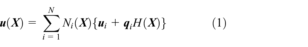
where

However, the approximation given in equation (1) does not yield
The XFEM with the phantom node method was used for the basic formulation, to demonstrate the enriched DOF locking. The discontinuous displacement field
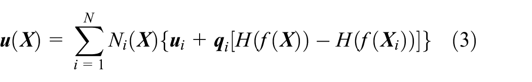
where

Representation of a discontinuity in a truss element for XFEM with the phantom node method.
The truss element with two nodes is first discussed to illustrate the process of applying the phantom node method to XFEM. Equation (4) is obtained by expanding equation (3) for the truss element. In this case,

When a crack occurs in element

As shown in Figure 2, phantom element
where

The region within the element in the range of
This process can be applied to quadrilateral elements with four nodes. Using the same method as before, the following equation is developed for the quadrangle element, by substituting

When a crack occurs in an element, a phantom node is added as shown in Figure 3, and a phantom element is formed according to the crack. Thereafter, the DOF of each phantom element is as follows
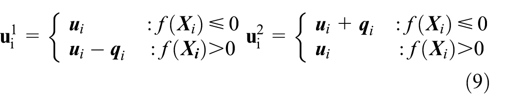
Representation of phantom nodes in a quadrilateral element by crack type: (a) completely cracked elements and (b) partially cracked elements.
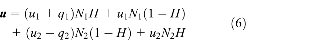
Equation (7) was then further expanded by duplicating it with the multipliers

The aforementioned equation is then rewritten as
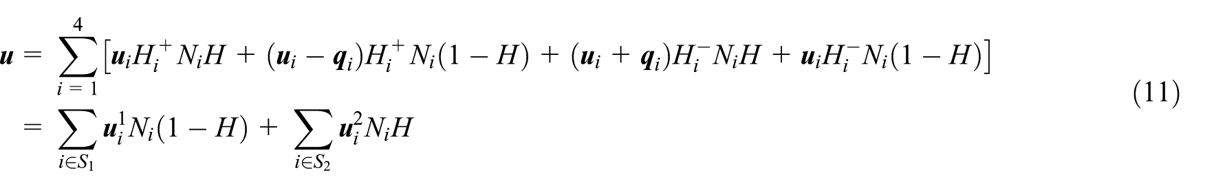
where
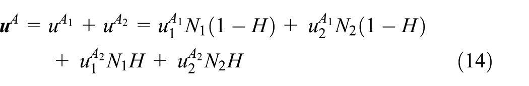
In equation (11), the two terms in the second equation represent the displacement fields of phantom elements
Enriched DOF locking
Two-node truss elements
Figure 4 presents the relationship between the elements and cracks when two adjacent elements are cracked. When two neighboring elements A and B are cracked, the locations of the two cracks are given by


The arrangement of phantom nodes when the enriched DOF locking occurs in truss elements.
The enriched DOFs added to each real node are denoted by

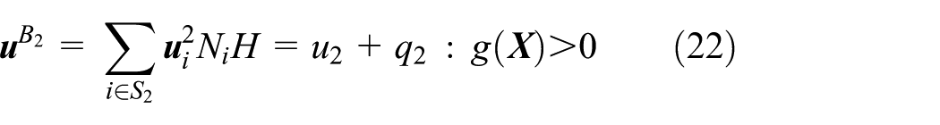
The displacement field of phantom elements


where
Using


As mentioned earlier, nodes 5 and 5′ are identical, and

It can be said that phantom node 5 does not exist and that no cracks are present if two cracks develop on adjacent elements.
Figure 5 illustrates various cracking scenarios on the one-dimensional element mesh. Figure 5(a) presents the mesh before cracking, and Figure 5(b) presents the separated elements

Various cracking scenarios: (a) before cracking, (b) an unlocked crack on element A, (c) two locked cracks on elements A and B, (d) three locked cracks on elements A, B, and C, and (e) two unlocked cracks on elements A and C.
Four-node quadrilateral elements
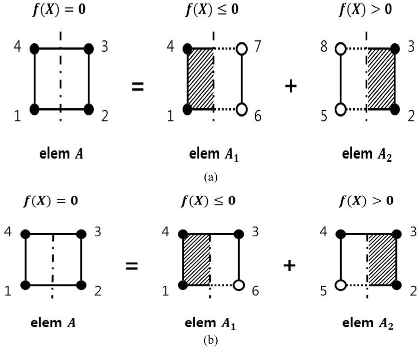
To represent and interpret the cracks of the actual material, four-node quadrilateral elements were used rather than two-node truss elements. As shown in Figure 6, it was assumed that two cracks developed simultaneously on the adjacent elements

The arrangement of phantom nodes when the enriched DOF locking occurs in quadrilateral elements.
Equation (10) or (11) was also used to demonstrate how the enriched DOF locking occurs in the quadrilateral element. Similar to the truss element, the aforementioned equation is developed for phantom elements

Likewise, the displacement at phantom node 8′ in the phantom element
As can be seen in equations (18) and (19),
Numerical examples
Simply tensioned bar
It was verified that the enriched DOF locking develops when two cracks occur simultaneously on the adjacent elements. In this section, the effect of the enriched DOF locking is demonstrated using Abaqus,
36
which is a commercial finite element analysis program implementing the XFEM feature. First, three 10 mm × 10 mm elements were arranged adjacent to each other, and a pinned boundary condition was applied at nodes 1 and 5, as shown in Figure 7(a). The material is assumed to be linear elastic with the Young’s modulus
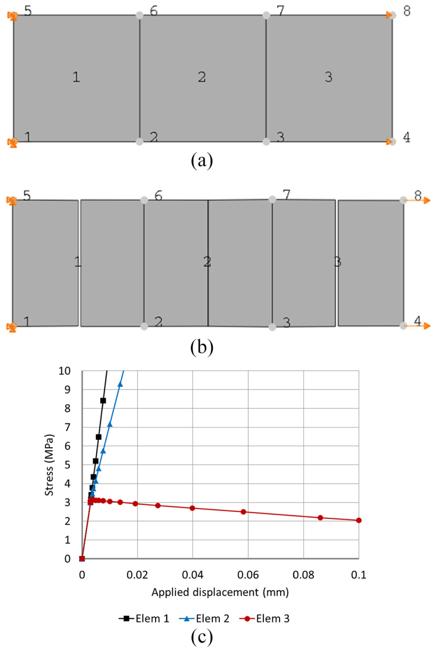
Analysis of a simply tensioned bar with the enriched DOF locking: (a) the undeformed shape, and boundary and loading conditions, (b) the deformed shape where the enriched DOF locking occurred, and (c) the principal stress–displacement graphs.
The deformed shape of the case with the enriched DOF locking is presented in Figure 7(b). Although the deformed shape had full penetrated cracks in all elements, the analysis continued like a linear elastic analysis. Figure 7(c) presents the principal stress at the center of each element, according to the magnitude of the applied displacement. Even after reaching a tensile strength of 3 MPa, the stress of elements 1 and 2 increases. The reason for this is that the discontinuity of the displacement field is not correctly calculated due to the locking of the phantom node. The calculated stress of element 3 gradually decreases because it represents the stress of one of the overlapped elements with a free edge, as shown in Figure 5(d). The stresses shown in Figure 7(c) correspond to the stresses in elements A1, B1, and C1 shown in Figure 5(d).
To solve the enriched DOF locking problem, it is necessary to ensure that the stresses or strains of adjacent elements do not simultaneously satisfy the crack initiation criterion. To achieve this, it is proposed that the tensile strength of the neighboring elements should be slightly increased. The tensile strength of the dark-shaded elements shown in Figure 8(a) is increased from 3 to 3.1 MPa. The tensile strength of the light-shaded element is retained as 3 MPa. Considering the heterogeneity of concrete, the suggested method to evade the enriched DOF locking is acceptable. Figure 8 presents the result of the case without the locking, which was solved using the proposed method. Due to the slightly increased tensile strength of elements 1 and 3 to circumvent the enriched DOF locking, only one crack developed in element 2, as shown in Figure 8(b). The locking did not occur at the phantom node between the adjacent elements. Thus, the discontinuous displacement in element 2 was calculated correctly. Moreover, as the applied displacement increased, the principal stress in element 2 decreased and reached zero after reaching the tensile strength. The stresses in elements 1 and 3 were also released since the entire structure was completely separated after cracking as shown in Figure 8(c).

The results of a simply tensioned bar where the enriched DOF locking is circumvented: (a) assigning slightly higher tensile strength to the neighboring elements, (b) the deformed shape without the enriched DOF locking, and (c) the principal stress–displacement graphs.
Reinforced concrete beam
Next, the effect of the enriched DOF locking on the actual reinforced concrete structure was investigated. The shape of this specimen is presented in Figure 9. The material properties of the concrete were as follows: Young’s modulus = 33.1 GPa, Poisson’s ratio = 0.18, tensile strength = 3.67 MPa, and fracture energy
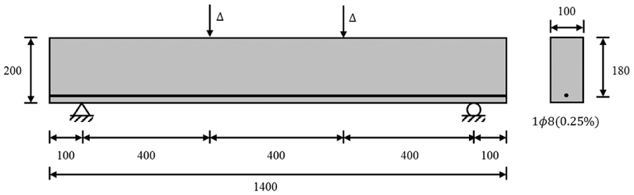
Dimensions of reinforced concrete beam (mm).
When the displacement was applied to the reinforced concrete beam, several cracks simultaneously developed at the center one-third portion of the beam because the concrete elements on the bottom side in this region were subjected to uniform tensile stress. As shown in Figure 10(a), the locking occurred because the cracks developed simultaneously in the adjacent elements located in this region. Figure 10(d) shows that the tensile stress at the bottom center element linearly increases as the applied displacement increases when the enriched DOF locking occurs. To evade the locking, the proposed method of assigning slightly higher tensile strength to the neighboring elements was also applied for this case as in the simply tensioned bar. By assigning slightly different material properties such as tensile strength, it is possible to ensure that the stresses or strains of adjacent elements do not simultaneously satisfy the crack initiation criterion. The location for the element with higher tensile strength can be easily determined by observing the crack pattern of the beam with locking as shown in Figure 10(a).

The results of the reinforced concrete beam: (a) crack pattern of the reinforced concrete (RC) beam with locking, (b) analysis mesh to evade the enriched DOF locking, (c) crack pattern of the RC beam without locking, and (d) principal stress at the bottom center element versus applied vertical displacement.
Figure 10(b) shows the analysis mesh in which the tensile strength of the dark shaded elements was modified from 3.67 to 3.8 MPa. Only two elements—in the bottom layer at the center one-third portion—were modified because the cracks will propagate without locking once the initial locking is evaded. A trial was also conducted by modifying one element, but the enriched DOF locking still occurred. As a result, cracks initiated at the unmodified bottom elements and propagated upward as shown in Figure 10(c). The tensile principal stress at the bottom center element of the case without the locking is also shown in Figure 10(d). When the locking occurred, the stress in the locked element linearly increased beyond the tensile strength. On the contrary, the model analyzed without the locking revealed that the stresses were released after the tensile strength was reached. However, the stress did not drop to zero because the cracked concrete was completely constrained to the reinforcement.
Conclusion
In this study, the enriched DOF locking that can occur in XFEM analysis was investigated. It was verified that the inactivated discontinuous displacement field was due to the enriched DOF locking, which occurred when two adjacent elements shared the enriched DOF. Although the phantom node method was used in the verification, the enriched DOF locking could occur in all versions of the XFEM, unless another set of enriched DOFs was provided. The enriched DOF locking occurs when two adjacent elements are cracked simultaneously according to the crack initiation criterion. The crack initiation criterion determines the given element cracked if the analysis result of the element, such as the principal stress, exceeds the user-defined value. The analysis results can exceed the criterion at a load increment when the analysis model has a relatively uniform stress distribution over a certain range, due to the geometric characteristics or the stress transfer through the interconnected elements such as the reinforcing bars. Numerical examples of a simply tensioned bar and a reinforced concrete beam were presented to demonstrate the two structures prone to enriched DOF locking. Moreover, a simple method of increasing the tensile strength of the neighboring elements to circumvent the enriched DOF locking was proposed. By modifying the tensile strength of the neighboring elements, the simultaneous cracking of two adjacent elements can be evaded. Applying these methods to prevent enriched DOF locking enabled the achievement of appropriate cracking analyses, which revealed the discontinuous displacement fields and the release of the stress in the cracked elements after cracking. The number of modified elements can be minimized because the cracks will propagate properly once the initial locking is evaded. Considering the heterogeneity and variability of concrete, the proposed method of modifying the tensile strength by less than 5% is acceptable. The proposed method is simple and easy for practicing engineers since it does not involve computer programming, such as user subroutines, or complicated combination of model parameters. This method can be easily applied to the three-dimensional crack propagation analysis.
Footnotes
Handling Editor: James Baldwin
Declaration of conflicting interests
The author(s) declared no potential conflicts of interest with respect to the research, authorship, and/or publication of this article.
Funding
The author(s) disclosed receipt of the following financial support for the research, authorship, and/or publication of this article: This work was supported by Konkuk University in 2016.