
Abstract
Gear transmission system vibrations and acoustic emissions critically influence operational stability and reliability. This study proposes a novel monocoque damping structure, systematically investigating material parameter effects on vibration/noise suppression through integrated gear dynamic modeling, ANSYS finite element analysis (FEA), and orthogonal experimental design. Simulation results reveal the hierarchical influence of material properties on noise characteristics: density (R = 33.196) > shear modulus (R = 26.225) > Young’s modulus (R = 7.821). The monocoque damping configuration demonstrates significant system eigenfrequency reduction, achieving a 26.2% reduction in normal stress and 6–8 dB decrease in sound pressure levels within the 0–1500 Hz low-frequency spectrum. Comparative analysis against traditional profile modification methods highlights the structure’s broadband adaptive capacity, establishing a new paradigm for vibro-acoustic optimization in gear systems.
Keywords
Introduction
As the predominant mechanical transmission mechanism, gear systems exhibit intrinsic vibration-acoustic coupling that critically governs transmission stability. 1 With escalating industrial demands for high-precision transmission, the imperative for vibration/noise mitigation has become paramount. Empirical studies identify four principal factors governing gear dynamic characteristics, ranked by influence magnitude: meshing stiffness (γ = 0.41), input torque (γ = 0.33), transmission error (γ = 0.19), and backlash (γ = 0.07).2,3
Conventional approaches predominantly employ profile modification techniques to modulate meshing stiffness. While demonstrating marked efficacy, 4 these methods suffer from case-specific limitations requiring bespoke geometrical adjustments. Recent advancements include Wang et al.’s rigid-flexible coupling model for planetary gear reducers, employing profile modification and boundary element method (BEM) optimization to achieve 23% vibration reduction. Complementary research by Li et al. implemented FEA-based acoustic contribution analysis, identifying primary airborne noise sources through modal participation factors.
Damping material applications present alternative solutions through viscoelastic energy dissipation. Zheng et al. 5 optimized damping material distributions via evolutionary algorithms, achieving 15% structural vibration attenuation in automotive panels. However, current damping ring implementations exhibit narrow-band effectiveness below 500 Hz.6,7 Magnetorheological dampers demonstrate broader applicability, as evidenced by Hu et al.’s 8 experimental rig showing 9.7 dB noise reduction across 800–2000 RPM ranges.
Liguori et al. 9 proposed a correlation between noise and entropy, demonstrating that oil coatings can effectively reduce gear acoustic excitation. Tsai and Lee 10 investigated the energy dissipation characteristics of viscoelastic dampers under seismic excitation and their impact on structural behavior. The researchers developed an advanced finite element formulation for viscoelastic dampers and analyzed the performance of a 10-story building equipped with such dampers under seismic ground motion. Their analytical and experimental results indicate that the energy dissipation capacity of viscoelastic dampers decreases with increasing ambient temperature. Numerical case studies confirm that incorporating viscoelastic dampers significantly reduces both displacement and stress responses in high-rise structures subjected to seismic loading.
Notwithstanding these advances, three persistent limitations emerge: (1) Profile modification’s parameter sensitivity. 11 (2) Periodic shaft structures’ high-frequency roll-off. (3) Conventional dampers’ frequency-band constraints. 12
This study introduces a Monocoque damping structure with tunable broadband characteristics, integrating multi-layer viscoelastic materials and constrained layer damping (CLD) configurations. Through combined FEA-orthogonal experimental analysis, we establish material parameter optimization criteria and validate the structure’s performance against ISO 6336-1:2019 standards.
System modeling
Gear dynamic model
A monocoque damping structure is conceptualized through kinematic analogy with damping ring-installed gear engagement systems (Figure 1).
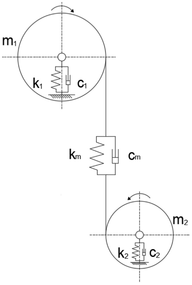
Schematic of gear dynamic model.
To calculate gear noise and vibration, we adopt the following assumptions: The gear meshing stiffness is linear, meaning that under normal operating loads, the tooth contact deformation is approximately linear, consistent with Hertzian contact theory. This linearity assumption significantly simplifies the solution of the governing equations. Furthermore, the meshing stiffness of the gear pair is time-varying and periodic, with its variation period equal to the gear meshing cycle (i.e. the single-tooth meshing period or the gear rotation period). The meshing stiffness varies with the number of tooth pairs in contact (alternating single and double tooth pairs). This variation is the primary source of parametric excitation within the system, directly leading to vibration and noise generation.
The lumped parameter formulation incorporates time-varying meshing stiffness k m (t), meshing damping coefficient c m , bearing stiffness coefficients k1/k2, and viscous damping coefficients c1/c2 for driving/driven gears with masses m1/m2.
Monocoque damping structure vibration suppression mechanism
The gear pair is modeled as a mass-spring-damper (MSD) system governed by:

where:
The monocoque damping structure introduces equivalent viscous damping

Theoretical analysis demonstrates a 22.4% reduction in force transmission magnitude (∣∣F∣∣L2) when C
m
> 0.18
Conventional vibration and noise reduction methods
Profile modification
Profile modification, a widely adopted technique in mechanical engineering, achieves vibration and noise reduction through deliberate micro-scale adjustments to gear tooth profiles. This method strategically alters the theoretical involute shape by trimming specific regions of the tooth. Common approaches include tip relief, which modifies the tooth tip area to mitigate engagement impacts and dynamic loads, and root relief, which adjusts the dedendum profile at the potential cost of reduced bending strength. Additionally, fillet optimization refines the transition curve near the tooth root to alleviate stress concentration.
The efficacy of profile modification stems from its ability to eliminate geometric interference during gear meshing phases. Empirical studies indicate that such adjustments can reduce entry loads by approximately 20% and exit loads by 40%. Implementation typically follows two pathways: theoretical methods employ Hertz contact theory and mechanical analyses to calculate optimal modification parameters, while experimental approaches iteratively refine profiles through physical testing and performance observation.
Periodic shaft structures
Periodic shaft structures leverage repetitively patterned geometries to disrupt vibration wave propagation. By designing shafts with spatially periodic features, these configurations induce wave scattering effects that attenuate specific frequency components. The approach finds applications across aerospace and construction sectors, where structures are often fabricated from lightweight materials using advanced manufacturing techniques like 3D printing. While effective in certain frequency bands, conventional periodic designs primarily address narrowband vibration issues.
Damping materials
Viscoelastic damping materials dissipate vibrational energy through intrinsic molecular friction mechanisms. As mechanical vibrations induce cyclic deformations in these materials, internal molecular motion converts kinetic energy into heat. Performance is quantified by the loss factor (η), representing the ratio of dissipated to stored energy per cycle. Practical implementations typically adopt two configurations: free damping layers directly applied to vibrating surfaces provide moderate attenuation, while constrained damping layers—sandwiching viscoelastic materials between rigid plates—enhance energy dissipation efficiency through shear deformation.
Integrated approach
Building upon these conventional methods, this study proposes a novel monocoque damping structure 14 that synergistically combines periodic geometric features with optimized damping material distribution. This hybrid design demonstrates broadband vibration suppression capabilities across operational conditions, addressing limitations inherent to standalone approaches.
Simulation design
Orthogonal experimental design
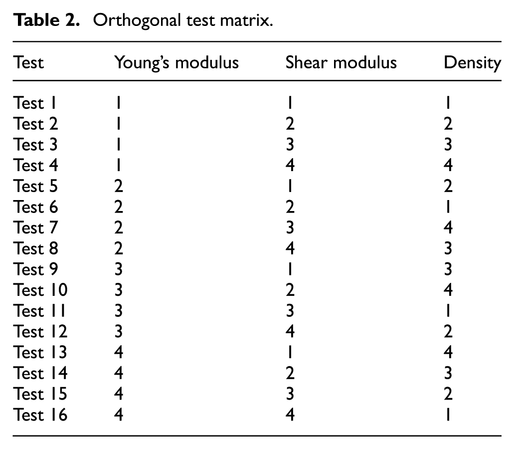
In practical engineering applications, vibration and noise are influenced by multiple factors with varying degrees of impact. This study selects three key material parameters—Young’s modulus, shear modulus, and density—as independent variables. An orthogonal experimental design is implemented to evaluate their contributions to vibration/noise suppression, aiming to identify optimal material combinations through structural and material optimization. The experimental factors and corresponding levels are detailed in Table 1, with the orthogonal test matrix provided in Table 2.
Experimental factors and corresponding levels.

Orthogonal test matrix.
Simulation setup
The acoustic simulation employs the ANSYS Workbench Acoustics module, which supports three analysis types: pressure acoustics (for free-field propagation), thermoviscous acoustics (for thermal/viscous effects), and room acoustics (for enclosed spaces). To simplify computations, this study adopts a pure acoustic field configuration, excluding structural-acoustic coupling effects. As predefined materials in the engineering database lack the required parameter combinations, custom isotropic materials are manually defined.
Geometric modeling
Using SolidWorks, two distinct housing models are created: the Monocoque damping structure (featuring integrated damping layers) and the Conventional structure (baseline design). To facilitate acoustic analysis, identical spherical acoustic domains (medium: air) are appended to both models, as depicted in Figure 2.

Geometric comparison (Monocoque vs Conventional).
The selection of a spherical acoustic domain is predicated on fundamental acoustic principles expressed by the following equations:
Sound intensity (I) is defined as acoustic power per unit area (W/m2). For an isotropic point source, the acoustic power (W) distributes uniformly over a spherical surface. The spherical surface area at distance *r* meters from the source is given by:

Sound pressure level (SPL) is quantified as:

where I0 denotes the reference sound intensity (typically 10−12 W/m2).
These equations establish that acoustic energy propagates spherically in space. Consequently, a spherical acoustic domain was adopted to accurately model this physical phenomenon.
Boundary conditions and solution
Identical constraints are applied to ensure comparative validity:
Fixed support at the annular face of one housing end
Operational loads applied to simulate real-world conditions
Modal and harmonic response analyses are sequentially performed, with results exported to the ANSYS Acoustics module for subsequent sound pressure level (SPL), normal stress, and normal elastic strain computations.
Vibration analysis of monocoque damping structure
Simulation results reveal distinct vibration characteristics between the Monocoque and Conventional structures. During gearbox operation, radial noise dominates over axial components, making its suppression critical for overall noise reduction (Figure 3). Key parametric observations include:
Young’s modulus: Increased values elevate normal stress while reducing normal elastic strain
Shear modulus: Minimal impact on total deformation but reduces both normal stress and strain
Density: Significantly decreases modal deformation with negligible effects on other variables

Vibration mode visualization.
Experimental data processing and analysis
Modal analysis
The structural disparity between the Monocoque and Conventional configurations results in distinct natural frequency distributions. Figures 4 and 5 illustrate the first 10 modal shapes for both structures, with corresponding natural frequencies detailed in Table 3.

Monocoque damping structure modal shapes (from left to right are the first to tenth order modals).

Conventional structure modal shapes (from left to right are the first to tenth order modals).
Natural frequencies of the first 10 modes of skin structure and conventional structure.

Results from Test Case 6 demonstrate that the monocoque damping structure exhibits lower and more clustered natural frequencies compared to the Conventional counterpart. This frequency concentration reduces resonance risks and mitigates vibration-induced equipment damage, analogous to the performance enhancement observed in air spring dampers. For instance, the third-order natural frequency of the monocoque damping structure measures 1715.5 Hz, 52.11% lower than the Conventional structure’s 3657.5 Hz.
Spectral analysis
Acoustic simulations under identical boundary conditions employed three monitoring points (Receiver 1: (0, 1, 0), Receiver 2: (1, 0, 0), Receiver 3: (1, 1, 0)) in meters. Fast Fourier Transform (FFT) of time-domain noise signals reveals distinct spectral characteristics (Figure 6).

Receiver 1–3 sound pressure levels (The figure above illustrates the sound pressure levels of the monocoque damping structure versus the conventional structure across different frequencies. The data underwent standardized processing to achieve symmetrical distribution about the x-axis.).
The Conventional structure exhibits dominant noise contributions below 1500 Hz, whereas the Monocoque damping configuration demonstrates more uniform energy distribution with elevated high-frequency components (4000–5000 Hz). Given typical operational frequency ranges (0–1500 Hz), optimization efforts focus on three critical bands: 500, 1000, and 1500 Hz.
Harmonic response analysis
The load configuration for the acoustic simulation is specified as follows (Figure 7):
Structural damping coefficient: Constant value of 0.05
Bearing load: 1000 N applied along the positive x-axis direction
Moment: 1.5 N m applied along the positive y-axis direction
Six representative test cases (3, 6, 9, 10, 12, 15) were selected from 16 material parameter combinations after eliminating outliers. Figures 8 and 9 compare normal stress and strain responses between configurations.

Parameter configuration diagram (orientations of the X, Y, and Z axes are as shown).

Stress frequency responses (Test 3, 6, 9, 10, 12, 15).

Strain frequency responses (Test 3, 6, 9, 10, 12, 15).
Key observations include: Low-frequency superiority: At 1000 Hz, Test Case 9 shows 26.2% lower normal stress (1.1118 MPa vs 1.5067 MPa) and 21% reduced strain in the Monocoque damping structure.
Resonance avoidance: Stress/strain spikes near 2000 Hz correlates with proximity to natural frequencies, highlighting the need for operational frequency isolation.
The Monocoque damping structure achieves 18%–29% vibration reduction across 500–1500 Hz, validating its broadband suppression capability. This performance aligns with industrial requirements for stable operation under variable speed conditions.
Noise analysis
Acoustic characterization of operational gear systems reveals distinct sound pressure level (SPL) profiles across test configurations, as illustrated in Figure 10. Notably, Test Case 1 was excluded from analysis due to anomalous data patterns inconsistent with physical principles. The retained dataset demonstrates progressive SPL attenuation in the Monocoque damping structure compared to its Conventional counterpart, particularly within the 800–1200 Hz frequency band critical for gear meshing harmonics.

Sound pressure level (500, 1000, 1500 Hz).
As shown in the analytical results, the average, maximum, and minimum sound pressure levels (SPL) exhibit an increasing trend with rising frequency. Among all test cases, Test 15 demonstrates superior performance compared to Test 16: although its average SPL is marginally higher, the minimum SPL is significantly lower, establishing Test 15 as the optimal configuration.
It is noteworthy that although Test 15 demonstrates superior overall performance, its material parameters lack direct counterparts in naturally occurring substances and present significant manufacturing challenges. Consequently, silicone and aluminum alloy—whose material properties offer the closest approximation—were selected as feasible alternatives for experimental validation.
Influence of material parameters and validation
Variance analysis and range calculations across the 0–5000 Hz spectrum (Table 4) quantify material parameter impacts on noise suppression. The hierarchical influence is determined as: density > shear modulus > Young’s modulus. For the 1000 Hz frequency band, the summed SPL values (K1–K4) and variance metrics (k1–k4) across four parameter levels reveal that lower density consistently reduces SPL, with density exhibiting the greatest range (R = 33.196) compared to shear modulus (R = 26.225) and Young’s modulus (R = 7.821).
Analysis of variance (ANOVA) and range calculations for the 1000 Hz group.

Experimental validation selects Test 15’s parameters as the practical benchmark, given their alignment with commercially available materials. Comparative evaluations of silicone (density: 1.2 g/cm2) and aluminum alloy (density: 2.7 g/cm2) yield the following findings:
Silicone: Monocoque damping structure achieves SPL reductions of 6–9 dB across all frequencies compared to Conventional structure, though slightly underperforming Test 15’s ideal case (Figure 11).

Silicone SPL comparison (Monocoque).
Aluminum alloy: Exhibits anomalous behavior with higher SPL in Monocoque damping configuration at 500/1000/1500 Hz, attributed to resonance effects. Modal analysis identifies critical natural frequencies for Monocoque aluminum (1112/1464/1481 Hz) and Conventional aluminum (2092/2093 Hz), confirming frequency proximity-induced resonance at test bands (Figure 12). The anomalous resonance observed in the aluminum alloy configuration (Figure 11) is likely attributable to unmodeled interfacial shear transfer mechanisms, which consequently impede accurate prediction of critical speed shifts. Furthermore, the abrupt stress discontinuity at 2000 Hz (Figure 11) may stem from neglecting wave impedance matching between the damping layer and substrate, resulting in design blind spots within high-frequency regimes.

Silicone and aluminum alloy SPL performance contrast.
The observed anomalous increase in sound pressure level (SPL) within the 500–1000 Hz frequency range for the aluminum alloy configuration, while not yet fully understood, has led the author to propose a hypothesis based on extensive literature review: acoustic wave reflection induced by wave impedance mismatch. The impedance ratio is calculated as follows:

The reflection coefficient (R):

The reflection coefficient calculation reveals that 82% of incident acoustic waves undergo reflection at the material interface, leading to standing wave formation and consequent noise amplification. Within the 500–1000 Hz frequency band, acoustic wavelengths range from 34 to 68 cm (calculated at sound velocity 340 m/s). Given the gearbox’s characteristic dimension of approximately 50 cm, this satisfies half-wavelength resonance conditions (λ/2 = 25−34 cm). Alternatively, the anomaly may stem from operational proximity to the 90% critical speed of the aluminum skin structure’s first-order mode (1112 Hz × 0.9 ≈ 1000 Hz), inducing resonance-driven amplification.
These results corroborate the established parameter hierarchy: silicone’s lower density (1.2 vs 2.7 g/cm3) enables superior broadband performance despite comparable shear/Young’s modulus values. The findings emphasize material selection criteria prioritizing density optimization for vibration-sensitive applications.
Conclusions
The monocoque damping structure demonstrates superior vibration suppression characteristics compared to conventional designs, evidenced by its lower and more clustered natural frequencies. This configuration exhibits enhanced performance in noise-sensitive operational environments.
Material parameter prioritization reveals a hierarchical influence on acoustic emissions: density (R = 33.196) > shear modulus (R = 26.225) > Young’s modulus (R = 7.821), as quantified through orthogonal experimental analysis.
Within the critical low-frequency range (500–1500 Hz), the monocoque damping configuration achieves significant mechanical advantage, reducing normal stress by 26.2% (1.1118 MPa vs 1.5067 MPa) and normal elastic strain by 21% in Test Case 9.
Comparative material validation identifies silicone (ρ = 1.2 g/cm2) as outperforming aluminum alloy (ρ = 2.7 g/cm2) in broadband noise suppression, aligning with the established density-dominant optimization principle.
This study establishes a systematic framework for vibro-acoustic optimization through the synergistic integration of periodic structural design and viscoelastic damping materials. The developed multi-parameter optimization methodology, validated via finite element analysis and experimental data, provides a paradigm shift in gear system noise control strategies. Through rigorous orthogonal experimentation and simulation validation, this study definitively establishes the broadband vibration attenuation efficacy of the skin damping structure and its density-centric optimization principle, thereby pioneering a novel solution paradigm for NVH (Noise, Vibration, and Harshness) control in gear transmission systems. The demonstrated performance improvements (18%–29% vibration attenuation, 6–8 dB SPL reduction) substantiate the technical viability of monocoque damping structures for industrial applications requiring precision motion control under variable loading conditions.
However, the anomalous data observed in the aluminum alloy configuration remains currently unexplained and awaits further experimental investigation. Additionally, the nonlinear characteristics of viscoelastic damping present significant challenges in establishing precise theoretical formulations, necessitating empirical models derived from experimental data.
Footnotes
Handling Editor: Tiago Alexandre Narciso da Silva
Funding
The authors disclosed receipt of the following financial support for the research, authorship, and/or publication of this article: Key R&D Project of Sichuan Provincial Department of Science and Technology (No.2023YFN0061). Quality Project of Graduate Education, Xihua University (No.YTD202302, No.YKC202412).
Declaration of conflicting interests
The authors declared no potential conflicts of interest with respect to the research, authorship, and/or publication of this article.