
Abstract
The assembly parameters of bearings are critical to the operational performance of rolling bearings. However, the relationship between these assembly parameters and service performance indicators remains unclear. To address this significant issue, this paper innovatively establishes a quasi-static model for paired tapered roller bearings. First, it establishes the correlation between assembly process parameters, such as preload and interference, and the clearance. Secondly, this study examines the differences in contact stress distribution and oil film thickness between the bearing rollers, raceways, and flanges under varying assembly parameters. Additionally, the influence of assembly process parameters on bearing performance metrics, including bearing stiffness, friction torque, and service life, is discussed. Finally, the validity of the simulation model is verified by the service performance test bench of the tapered roller bearing, and the influence of the assembly and adjustment process parameters on the service performance parameters of the matched tapered roller bearing is determined, so as to provide theoretical guidance for the bearing assembly and adjustment site.
Introduction
Bearings are essential components in rotating machinery, providing support and facilitating motion. Among these, tapered roller bearings (TRBs), as representative separable bearings, exhibit not only higher load-carrying capacity but also certain self-aligning capabilities. Consequently, they are extensively employed in large-scale equipment applications such as wind turbines, 1 helicopter gearboxes, and high-speed trains. 2
As separable bearings, TRBs are typically installed in pairs, requiring precise adjustment during installation to ensure optimal performance and life. Preload and clearance are two key parameters in this adjustment process. Unfortunately, in current engineering practice, the quality of bearing adjustment is often evaluated solely based on operational smoothness; only rarely are the individual service characteristics of the bearing considered during parameter setting or adjustment. Consequently, improper configuration of bearing assembly parameters can lead to bearing wear and fatigue failure, significantly reducing operational performance and service life. This not only causes economic losses but can also pose safety risks (as shown in Figure 1).

Bearing damage caused by poor setting parameters.
The primary reason for these issues is that the bearing adjustment parameters significantly affect bearing service performance, and the mechanisms underlying their influence are complex. To meet the performance requirements of high-precision applications such as differentials, wind power, and aerospace, bearings must exhibit extended service life, higher reliability, and greater stability. This prerequisite requires that bearings maintain optimal performance throughout their lifecycle. However, installation quality and parameter setting adjustments directly affect bearing clearance, leading to significant fluctuations in service performance. This demonstrates the importance of studying the impact of assembly parameters on the performance of paired tapered roller bearings.
In terms of bearing preload and friction and wear, Jain et al. 3 studied the relationship between preload and friction and wear of tapered roller bearings, and gave the limit value of preload loss of tapered roller bearings. Laderou et al. 4 developed a dynamic model to determine its influence on bearing friction loss and overall efficiency. Bercea et al. 5 based on the automobile drive axle. Considering the influence of the initial axial preload, Therefore, a method for selecting the appropriate axial preload was proposed.
Concerning preload and bearing stiffness, Wang et al. 6 analyzed the process of applying preload to the bearing and revealed the principles of two preload mechanisms. Guo et al. 7 considering the meshing stiffness, axial dynamic stiffness, and axial preload of the system, a new transient dynamic model of multi-bearing electric vehicle reducer suitable for transient conditions was established. Zhang et al. 8 proposed the temperature rise of the bearing, the deformation of the bearing and the spindle, and the actual preload are discussed. They are nonlinear and positively correlated with the speed and the initial preload. In terms of preload and clearance changes, Yu et al. 9 analyzed the influence of installation radial clearance, outer raceway waveform value, radial load, and rotational speed on the maximum contact load and preload of the bearing by taking the three-lobe raceway cylindrical roller bearing as an example. Sun et al. 10 studied the vibration of a kind of centrifugal pump with the bearing clearance and preload of deep groove ball bearing as the key parameters. The results show that the pump’s vibration will not decrease continuously with the increase of the bearing preload. Regarding preload and bearing vibration, Bal et al. 11 studied the vibration of the shaft in the rotating mechanical system supported by angular contact ball bearings under various preloads and proposed a dynamic bearing model. Finally, in the aspect of reasonable selection of preload, Dong et al. 12 proposed a structure based on a fiber Bragg grating gated sensor to identify the preload of thermal induction bearing.
Regarding interference and bearing service life, Kim et al. 13 analyzed the thermal expansion behavior of double-row tapered roller bearings. The results confirm that the fatigue life decreases rapidly due to the interference fit at a very high speed or meager oil supply flow rate. The thermal expansion of bearing components causes this interference fit phenomenon. Regarding interference and bearing stiffness, Lambert et al. 14 studied tapered roller bearings with interference fit. The main parameters of the study are the influence of preload, temperature, lubricant viscosity, excitation frequency, excitation amplitude, and rotational speed on the stiffness of the bearing. Jiang et al. 15 comprehensively analyzed the stiffness and fatigue life of deep groove ball bearings and determined the optimal matching of interference fit, preload and overturning moment. Liu et al. 16 discussed the influence mechanism of interference fit on the spindle bearing system and used it to modify the analytical model of the spindle bearing. In terms of the change of interference with working conditions: Wang et al. 17 studied the change of interference of bearing inner rings under different working conditions and established a fitting model of bearing interference considering centrifugal displacement and thermal displacement. In terms of interference and bearing contact load: Wang and Yuan 18 proposed a calculation model considering radial interference, analyzed the relationship between radial interference and contact force distribution, established a static bearing capacity curve, and analyzed the influence of radial interference, raceway groove curvature radius coefficient and initial contact angle on static bearing capacity. Corina-Mihaela et al. 19 used finite element analysis to verify the pressure and bearing capacity under simple loads with different proportions of axial load for a given interference pressure. Barmanov and Ortiko 20 studied the influence of interference on the radial displacement and axial displacement of rolling bearing rings. The calculation methods and mathematical models of bearings were reviewed and analyzed.
In summary, most of the existing researchers have studied the influence of axial preload on bearing contact load and fatigue life and studied the mapping relationship between contact characteristics and service characteristics of single-row bearings with constant pressure preload. The multi-parameter characteristics of paired tapered roller bearings under positioning preload should be systematically discussed. For the amount of interference, most scholars have studied its influence on the parameters such as stiffness and life of the spindle. It is a rare example to focus on the bearing, and the bearing analysis involves less comprehensive influence on the parameters such as bearing contact load, stiffness, oil film change, and friction torque. Therefore, in order to provide the actual bearing assembly site with the influence of different preload and interference on the multi-parameter characteristics of the bearing, it is urgent to study the influence of assembly and adjustment process parameters on the contact characteristics, stiffness, friction torque, oil film thickness, and service life of the bearing.
In this paper, taking the paired tapered roller bearing as the object, the influence of the paired tapered roller bearing on the contact characteristics, stiffness, friction torque, oil film thickness, and service life of the bearing under different preload and interference is established. The theoretical model and simulation model are established, respectively, and the verification test of the specific parameters is carried out on the performance test bench of the paired tapered roller bearing.
Modeling the mapping relationship between assembly parameters and bearing service performance
As illustrated in Figure 2, this represents a perspective view of a cylindrical roller bearing. With reference to Figure 3, the four components of a cone roller bearing primarily include an outer ring, an inner ring, rolling elements, and retainers. Please refer to Figure 4 for the specific structural parameters of a roller cone bearing. As shown in Figure 5, a diagram illustrating the structure of a cylindrical roller bearing arranged in a “back-to-back” configuration is categorized into “back-to-back,”“face-to-face,” and “series” arrangements based on the orientation of the rolling elements at both the large and small ends.

Perspective view of tapered roller bearings.

Four components of tapered roller bearing.
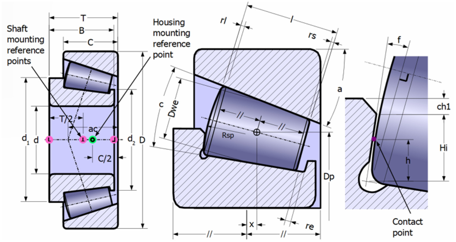
Structure parameters of tapered roller bearing.

“Back-to-back” arranged tapered roller bearings.
d is diameter of the bearing inner ring, D is outer diameter of the bearing, T is width of the bearing, C is outer width of the bearing, B is inner width of the bearing, Dp is radius of the shaft Based on the diameter of the central circular surface of the roller, Dwe is diameter of the bearing roller, I is total length of the bearing roller, rl is radius of the chamfer on the large end of the roller, rs is radius of the chamfer on the small end of the bearing roller, c is cone angle of the bearing roller. d1 is diameter of the large inner lip of the bearing, d2 is diameter of the small inner lip of the bearing, ch1 is chamfering of the edge of the large inner lip of the bearing. re is radius of curvature of the floating surface on the cylindrical bearing body, Rsp is radius of the spherical surface at the large end of the bearing, f is the angle formed between the rolling body and the lip, a is effective center distance, h is the contact height between the roller and the edge band, Hi is the height of the bearing shoulder, ac is edge angle, x is the radial displacement of the rolling element from the center of the bearing column.
Calculation of assembly and adjustment parameters-bearing clearance relationship
When under different working conditions, the appropriate assembly and adjustment parameters will be adopted according to the different weights of the performance parameters required by the bearing. At this time, the bearing will be in an optimal operating working clearance, making the comprehensive service performance optimal. Therefore, it is necessary to establish a theoretical model for the assembly and adjustment process parameters and clearance. When the clearance change caused by temperature deformation is not considered, the relationship between the clearance and the assembly clearance in the working state is obtained 21 :

In the formula, Δe is the working clearance and Δr is the assembly clearance:

In the formula, Δo is the initial clearance, Δa is the reduction of the downstream clearance under the action of axial preload, δf0 is the reduction of the interference fit clearance.
In the actual working conditions, the locking nut is generally used to preload the bearing. The tightening torque of the nut is M0, the diameter of the nut is d, and the theoretical deformation of the bearing (clearance reduction) is:

In the formula,
The bearing is preloaded according to the customer’s requirements when leaving the factory. The clearance measured before leaving the factory is the assembly clearance. During the assembly process of the bearing, the outer ring clearance fits and the inner ring interference fits:

In the formula, Δ D is the interference between the outer diameter and the shaft, D is the outer diameter of the bearing, De is the average inner diameter of the outer ring, and Dh is the outer diameter of the hub of the bearing seat.
Calculation of preload-bearing stiffness relationship
The deformation calculation of the bearing is based on the Hertz contact theory. Under the load, the contact between the rolling element and the ring produces elastic deformation, which in turn causes the relative elastic displacement of the inner and outer rings of the bearing in the load direction. This relative displacement is also called the deformation of the bearing, and the bearing stiffness is defined as the load required for the unit relative deformation of the inner and outer rings of the bearing in the load direction. Thus, calculating the bearing deformation under only preload, it is considered to be no radial load 22 :

In the formula, α is the external contact angle of the bearing (°); Qmax is the maximum load of the rolling element (N); l is the effective length of the roller (mm).
The bearing stiffness can be expressed as:
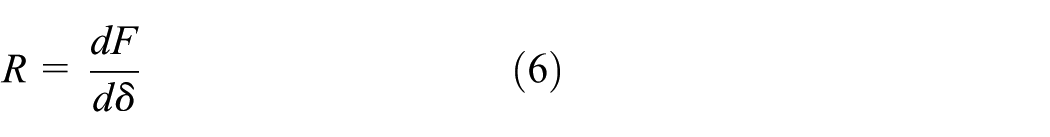
In the formula, F is the load of the bearing, that is, axial load, radial load, and torque; δ is the elastic deformation of the inner and outer rings of the bearing in the corresponding load direction.
According to the different directions of load and deformation, the bearing radial stiffness is expressed as:

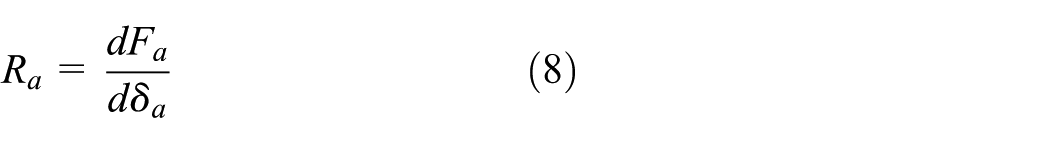
The axial stiffness of the bearing is expressed as:
The angular stiffness of the bearing is expressed as:

In the formula, Fr, Fa, and M are the bearing’s radial load, axial load, and torque, respectively. δ r , δ a , and δθ are expressed as radial deformation, axial deformation, and angular deformation, respectively.
Calculation of minimum oil film thickness of bearing
The maximum Hertz contact stress between the rolling element and the ring in the rolling bearing is generally between 1500 and 4000 MPa, and the lubrication state of the contact area should be considered according to the elastohydrodynamic lubrication.
According to the calculation method of line contact elastohydrodynamic oil film thickness under isothermal conditions, the minimum oil film thickness between the roller and the ring can be calculated by the following formula 23 :

In the formula: α is the viscosity of the pressure index; η is the dynamic viscosity under normal pressure; θ is the average surface velocity; K is the equivalent radius of curvature; E0 is equivalent to elastic modulus; q is the load per unit contact length.
The following formula calculates the average surface velocity:

In the formula, n is the inner ring or outer ring speed (r/min); γ is a dimensionless geometric parameter; dm is the pitch diameter (mm).
The equivalent radius of curvature is expressed as:

In the formula, the upper symbol applies to the inner ring, and the lower symbol applies to the outer ring, in which R1 is the radius of the roller; R2 is the raceway radius; RW is the roller diameter.
Bring equations (11) and (12) into equation (10) to get the following formula:
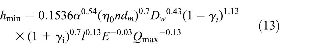
The minimum oil film thickness of the roller and inner raceway:
The minimum oil film thickness of the roller and outer raceway:
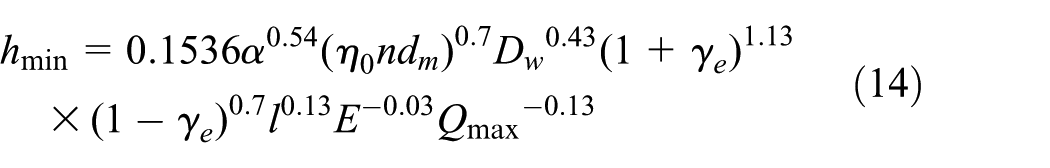
In the formula, the unit of hmin, Dw, dm, l is min, and the unit of α is Pa−1; the unit of η0 is Pa s; the unit of n is r/min; the unit of E is Pa; the unit of Qmax is N.
Calculation of friction torque
The primary source of friction torque caused by external load is the friction power consumption caused by differential sliding and elastic hysteresis. The expression is 23 :

Friction torque caused by lubricant viscosity, its size is related to the maximum speed of the bearing, the use of the lubricant and the viscosity coefficient of the lubricant. The formula is expressed as:

In the formula: f0 and f1 represent two calculation coefficients, respectively; Fβ represents the equivalent dynamic load of the bearing; dm represents the diameter of the bearing pitch circle.
Calculation of bearing service life
The life calculation method of L-P is based on ordinary bearing steel and general working conditions to determine the life reliability of 90%. Taking into account the influence of materials and conditions of use, as well as the requirements of high reliability, the International Organization for Standardization has made the following corrections to the life equation:
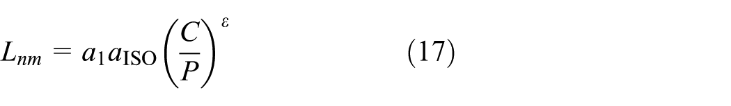
In the formula, Lnm is the fatigue life corresponding to the use probability (reliability); a1 is the reliability life correction coefficient; aISO is the correction coefficient of bearing life; C is the rated dynamic load; and P is the equivalent dynamic load.
Simulation analysis of the influence of assembly and adjustment parameters on bearing service performance
Simulation modeling
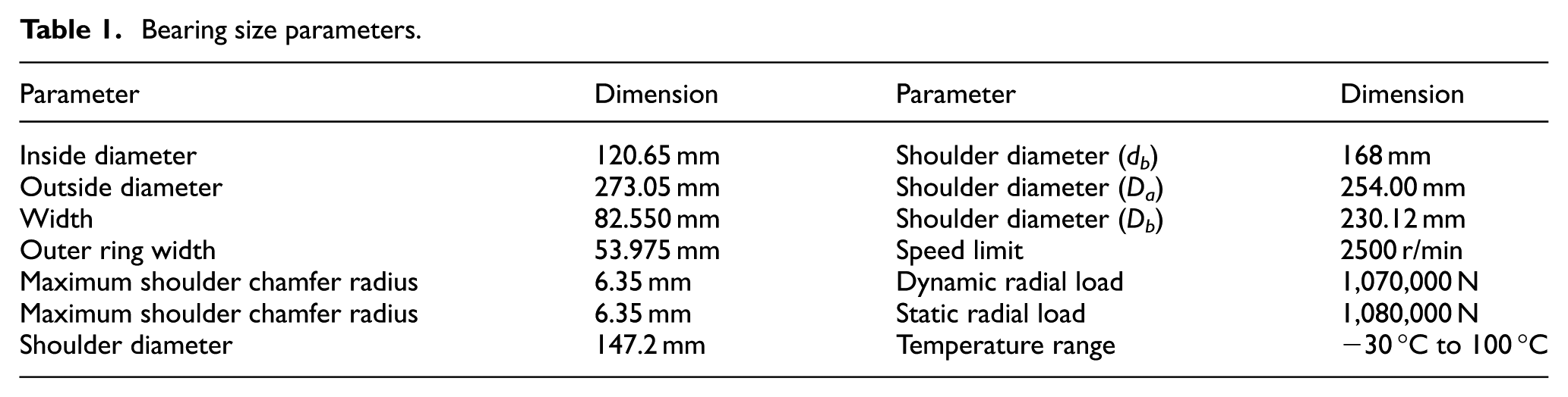
The size parameters of the tapered roller bearing are shown in Table 1 below. As shown in Figure 6, the Romax simulation model of the paired tapered roller bearing is defined. The roller row with increased load under axial load is defined as the first row, and the roller row with reduced load is defined as the second row. The three-dimensional coordinate system is the global coordinate system, the direction of modeling positioning and load loading is all based on this coordinate system. In addition, the centrifugal effect of the bearing under dynamic conditions is taken into account in the simulation analysis. The static analysis solver type is MKL sparse direct solution method, the bearing friction model is Palmgren model. The minimum stiffness ratio of the bearing in the non-load direction is established at 1 × 10⁻⁵, with the force convergence accuracy set to 1 N, the displacement convergence accuracy set to 5 × 10⁻² μm, and the velocity convergence accuracy set to 0.1 rpm. The lubrication type is oil lubrication, the lubricating oil is ISO VG 150 PAG Synthetic, and the ISO 4406 particle size code is –/17/14. When the temperature is 30 °C–100 °C, the kinematic viscosity is 235.005–26.678 mm2/s. The surface of the spindle is set to be treated by nitriding heat treatment and polishing.
Bearing size parameters.

Romax paired tapered roller bearing model. (a) Modeling diagram. (b) Force diagram.
The influence of preload on the service characteristics of bearings
The back-to-back pairing of two single-row tapered roller bearings is used as a paired tapered roller bearing. Set the amount of interference to zero, the external radial load FX = −50,000 N, the axial load FY = 10,000 N, the speed n = 500 r/min, and the ambient temperature T = 30 °C, the preload is adjusted from 3000 to 30,000 N, and the interval is 3000 N, that is, the contact load, stiffness, oil film thickness, friction torque, and modified life characteristics of the bearing are analyzed and studied under 10 preload conditions.
The influence of pre-tightening force on clearance
This article implements preload on the bearings in a fixed clearance manner by directly establishing the clearance value, which corresponds one-to-one with the bearing preload and is reflected in the bearing analysis results. As illustrated in Table 2, an increase in bearing preload leads to compression between the inner and outer rings of the bearing and the rolling elements, resulting in a negative change in clearance. In other words, as the bearing preload increases, the absolute value of the clearance gradually rises, although the rate of increment diminishes. During the transition of the bearing clearance from −27.60 to −91.00 µm, the variation amplitude of the clearance decreases from 37.3% to 6%. This suggests that the diminishing amplitude of clearance variation is primarily attributed to the constraints imposed by the hardness and tensile strength of the bearing material. As the preload increases, it approaches the tensile strength limit of the bearing material, rendering elastic deformation of the bearing increasingly challenging (Figure 7).
The percentage change of gap amplitude.


Relationship between pre-tightening force and clearance change.
Effect of preload on the full-circle contact characteristics of bearings
The contact load of the rollers in a tapered roller bearing serves as a fundamental basis for the analysis of bearing lubrication, friction, lifespan, and load capacity. A precise analysis and understanding of the internal load conditions of the bearing are essential for further evaluating the contact and friction performance of each component of the bearing. As shown in Figure 8, as the axial preload of the bearing linearly increases, the normal contact load between the rolling elements and the raceway of the first column bearing shows a gradually increasing pattern. Furthermore, under the same preload condition, the normal load between the inner ring and the rolling elements is nearly identical to the normal load between the outer ring and the rolling elements, showing a consistent load distribution pattern.

Relationship between preload and contact load. (a) Contact load of first row rolling element-raceway. (b) Contact load of second row rolling element-raceway.
At the same time, it can be seen from the figure that the load distribution of the bearing is symmetrically distributed with respect to the connecting line of the rolling elements at 0° and 180° positions. Furthermore, within the angle range from 0° to 180°, the normal load of the rolling elements on the raceway exhibits a gradually decreasing trend. At this time, the contact load of the paired tapered roller bearing is such that half of the rolling elements carry heavy loads while the other half carry light loads, which maximizes the service life of the paired tapered roller bearings and reduces the probability of bearing failure caused by fatigue damage or spalling in a specific area. The normal contact load of the rolling elements of the second column bearing is significantly smaller than that of the first column under the same preloading condition. Additionally, the load distribution of the second column bearing is also symmetrically distributed with respect to the connecting line of the rolling elements at 0° and 180° positions, and the normal contact load of the rolling elements on the raceway shows a gradually decreasing trend within the angle range from 0° to 180°. Unlike the first column bearing, the second column bearing has a normal contact load of 0 N for half of its rolling elements with the inner ring when the preloading is set at 3000 N, and the load condition of the seven rolling elements within the angle range from 102.857° to 257.143° consistently experiences low loads.
Effect of preload on bearing stiffness
As shown in Figure 9(a) below, the stiffness of the bearing is the stiffness of the bearing under the combination of contact stiffness and oil film stiffness, which is expressed as the ratio of axial or radial load to the relative displacement of the inner and outer rings. It can be seen from the following figure that the axial and radial stiffness of the first and second rows of the paired tapered roller bearings gradually increase with the linear preload increase. The specific stiffness changes are shown in Table 3 below. This shows that under the same working conditions, with the increase of the preload in the first row, the amplitude of the radial stiffness of the bearing is 7% higher than that of the axial stiffness. Similarly, the radial stiffness of the second column support has increased by 74 percentage points in comparison to the axial stiffness, indicating that it rises with the tightening force. However, the relative displacement between the inner and outer rings becomes more intricate, as the radial stiffness increases at a faster rate than the axial stiffness. Furthermore, the magnitude of change in the second row is more pronounced.

Relationship between preload and stiffness change. (a) Axial and radial stiffness variation trend with preload. (b) Angular stiffness variation trend with preload.
The stiffness of paired bearing changes with preload.

As shown in Table 4 and Figure 9(b), the angular stiffness increases gradually with the increase of preload. Because the angular stiffness of the second row bearing is opposite to that of the first row bearing, the overall angular stiffness of the bearing decreases gradually with the preload. As a result, the actual load of the second row bearing increases faster with the change of preload, resulting in a greater change in its angular stiffness.
Sensor parameters.

The influence of preload on bearing friction torque
As illustrated in Figure 10, the friction torque of the paired tapered roller bearings increases progressively with the augmentation of bearing preload. Furthermore, the friction torque of the second column of bearings consistently remains lower than that of the first column. Specifically, the friction torque of the first column bearing at a preload of 3000 N is 9.60 N m, and when the preload escalates to 30,000 N, the friction torque rises to 15.80 N m. Notably, the friction torque of the first column bearing at a preload of 30,000 N is 1.65 times that at 3000 N. In contrast, the friction torque of the second column bearing at a preload of 3000 N is 5.3 N m, and as the preload increases to 30,000 N, the friction torque reaches 11.50 N m. The friction torque of the second column bearing at a preload of 30,000 N is 2.17 times that at 3000 N. This phenomenon occurs because, as the preload increases linearly, the load carried by the first column bearing is consistently greater than that of the second column bearing. However, the variation in the load supported by the second column bearing is more pronounced with the increase in preload, leading to a more substantial percentage change in the friction torque of the second column bearing.

Relationship between preload and friction torque.
Effect of preload on oil film thickness of bearing
As illustrated in Figure 11, the minimum oil film thickness of both the inner ring and raceway of the first row of bearings, as well as that of the outer ring and raceway, exhibits a decreasing trend as the preload increases linearly. The minimum oil film thickness remains ∼1 µm. During the process of increasing the bearing preload from 3000 to 30,000 N, the minimum oil film thickness of the inner ring raceway of the first row of bearings decreased from 0.83 to 0.81 µm, reflecting a percentage change of 2.4%. Similarly, the minimum oil film thickness of the outer ring raceway decreased from 1.02 to 0.99 µm, corresponding to a percentage change of 2.9%. In contrast, the minimum oil film thickness of both the inner and outer ring raceways of the second row of bearings displays a trend of initially increasing followed by a decrease. Specifically, as the bearing preload was increased from 3000 to 30,000 N, the minimum oil film thickness of the inner ring raceway rose from 0.83 to 0.86 µm before returning to 0.83 µm, with a maximum percentage change of 3.6%. The minimum oil film thickness of the outer ring raceway increased from 1.02 to 1.04 µm and subsequently decreased back to 1.02 µm, with a maximum percentage change of 1.9%. This phenomenon is attributed to the continuous increase in the load borne by the first row of bearings, which results in an expanded actual contact area between the rolling elements and the inner ring, accompanied by a reduction in clearance.

Relationship between preload and oil film thickness.
Effect of preload on bearing life correction
As illustrated in Figure 12, given that the bearing operates under light load conditions, the primary focus of this analysis is on the variation of bearing service life in relation to linear increases in preload. In the first column, the bearing service life exhibits a linear decrease with increasing preload, diminishing from 2.56 × 10⁸ to 7.80 × 10⁷ h, reflecting a percentage change of 70%. In the second column, the service life initially increases before subsequently decreasing as preload increases. Specifically, when the preload ranges from 3000 to 15,000 N, the service life gradually increases from 3.61 × 10⁸ to 4.44 × 10⁸ h, representing a 12.3-fold increase. However, when the preload ranges from 15,000 to 30,000 N, the service life gradually declines from 4.44 × 10⁸ to 1.85 × 10⁷ h, indicating a reduction by a factor of 24. This phenomenon occurs because, as the bearing preload increases linearly, the absolute value of the bearing clearance in the first column gradually decreases, leading to an increase in the full contact load on the bearing, thereby heightening the stress on it. In the second column, the absolute value of the clearance initially increases and then gradually decreases, mirroring the behavior of the axial force. Consequently, the full contact load of the bearing also demonstrates a trend of first increasing and then decreasing, resulting in a parabolic distribution pattern for the corrected service life in the second column.

Relationship between pre-tightening force and modified life.
The influence of interference on the service characteristics of bearings
Similarly, the paired tapered roller bearing model mentioned above was used to study the bearing. When the preload is zero, the external radial load FX = −50,000 N, the axial load FY = 10,000 N, the speed is n = 500 r/min, and the ambient temperature T = 30 °C, the paired tapered roller bearing is used to study the bearing contact load, stiffness, oil film thickness, friction torque and modified life characteristics under six interference conditions when the interference is 50, 100, 150, 200, 250, and 300 µm, respectively.
The influence of interference on the full-circle contact characteristics of the bearing
As shown in Figure 13, the schematic diagram of the full-circle contact load of the paired tapered roller bearing under the five working conditions of the interference amount of 50 to 250 µm is listed here. It can be seen that with the linear increase of the interference amount, the full-circle contact load of the first row shows an apple-shaped distribution, and the maximum contact load between the roller and the raceway shows a decreasing trend. Respectively, the second row of the full-cycle contact load performance is concentrated in a pear-shaped distribution. The angular positions of the seven rolling elements that are mainly loaded are 0°, 25.714°, 51.429°, 257.143°, 282.847°, 308.571°, and 334.286°.

Relationship between interference and contact load (N). (a) The first row of bearing full-cycle contact load. (b) The second row of bearing full-cycle contact load.
The remaining seven rolling elements only have a load of 25 N in the average direction of the outer ring raceway, while the normal upward load of the inner ring raceway is 0 N. This is because considering the influence of the rolling element’s centrifugal force, at the speed of 500 r/min, the centrifugal force of the rolling element is 27.5 N, which causes the rolling element to squeeze the outer ring raceway and separate from the inner ring raceway.
At the same time, the rolling bodies at 0°, 205.714°, and 334.286° were selected as the reference for analysis. The maximum contact load between the rolling body and the outer ring decreased from 7992.9, 1460.1, and 8284.7 N to 7692.4, 1544.6, and 6519 N, respectively. From this, the contact load variation law of the rolling body and the inner and outer rings at the same position is consistent.
Effect of interference on bearing stiffness
As shown in Figure 14 below, with the linear increase in interference, the axial stiffness and radial stiffness of the first row show a decreasing trend. It can be seen that the radial stiffness decreases more significantly, while the axial stiffness of the second row increases gradually. The absolute value of angular stiffness shows a trend of increasing with the increase of interference, which is completely different from the change law of angular stiffness under the preload mentioned above.

The relationship between the magnitude of interference and the change of stiffness. (a) The change trend of axial and radial stiffness with interference. (b) The change trend of angular stiffness with interference.
Influence of interference on bearing friction torque
As shown in Figure 15 below, the friction torque of the paired tapered roller bearing increases gradually with the linear increase of the amount of interference. Among them, the amount of interference increases from 50 to 300 µm. It can be seen that the friction torque of the right side changes significantly faster than that of the left side, However, the friction torque of the second row is always smaller than that of the first row, which is because the load of the second row is always smaller than that of the first row.

The relationship between interference and friction torque.
The influence of interference on the thickness of bearing oil film
As shown in Figure 16, the minimum oil film thickness of the inner ring and the raceway in the first row and the minimum oil film thickness of the outer ring and the raceway decrease gradually with the increase of the interference. The minimum oil film thickness of the inner ring and the raceway in the second row and the minimum oil film thickness of the outer ring and the raceway increase first and then decrease.

Relationship between interference and oil film thickness.
Influence of interference on bearing life
As shown in Figure 17, the corrected life of the first row shows a trend of gradual shortening with the linear increase in the amount of interference, With the increase of the amount of interference, the speed of life-shortening is faster, In contrast, the corrected life of the second row increases first and then decreases with the increase of the amount of interference, This is because as the amount of interference increases, the absolute value of the first row clearance gradually decreases, resulting in a continuous increase in the friction torque, while the absolute value of the second row clearance will increase slightly at the initial stage and then gradually decrease with the axial component force, which makes the corrected life of the second row present an arched distribution law.

Te relationship between the amount of interference and the corrected life.
Experimental test of the influence of assembly and adjustment parameters on bearing service performance
Test bench and measuring point arrangement
The test bench is mainly composed of eight modules, including (1) drive system module, (2) spindle system module, (3) lubrication system, (4) loading module, (5) specimen module, (6) test system, (7) heating system, and (8) bearing test chambers. The system and modules are placed on the T-type table and fixed by bolts, The bearing performance testing platform, along with the installation process of the test bearing, is illustrated in the following Figure 18.

Paired tapered roller bearing performance test bench. (a) Three-dimensional structure of bearing performance test rig. (b) Bearing performance test rig. (c) Bearing installation process.
Figure 19 illustrates the physical diagram of the sensor arrangement and data acquisition system utilized for the performance testing rig of paired tapered roller bearings. Two eddy current sensors are strategically positioned at two locations on the spindle, with a phase angle difference of 90° to effectively monitor the spindle’s axial trajectory. Additionally, an eddy current sensor is radially installed on the bearing housing to measure the radial displacement of the bearing. Furthermore, two eddy current sensors are positioned axially 180° apart on the bearing housing, penetrating the end cap to assess the axial displacement of the bearing. The specifications of the eddy current sensors are detailed in Table 2, and the data acquisition frequency is set at 5120 Hz.

Sensor layout and acquisition system diagram.
Stiffness and friction torque test verification
Three different radial loads of FX = 10,000 N, FX = 12,000 N, and FX = 14,000 N are applied to the tested bearing. Under each radial load condition, the variation law of the stiffness of the bearing under five different axial preloads is discussed. The friction torque is measured by using the speed torque sensor to measure the overall torque of the test bench to verify the validity of the simulation model.
As shown in Table 5, when the radial load FX = 10,000 N, with the linear increase of the preload from 3000 to 11,000 N, the axial stiffness and radial stiffness of the first row of the paired tapered roller bearing show a significant increase trend. The second row’s axial stiffness and radial stiffness show a significant decrease. However, the total axial stiffness and total radial stiffness of the paired tapered roller bearings show an increasing trend.
Simulation of bearing stiffness under different preloads (FX = 10,000 N).

As shown in Figure 20, This shows that although the axial stiffness and radial stiffness of the first and second rows have their changes, the total axial stiffness and total radial stiffness of the paired tapered roller bearings show an increasing trend.

Bearing stiffness under different preload (FX = 10,000 N). (a) schematic diagram of stiffness change of each row of paired bearings. (b) schematic diagram of total stiffness change of paired bearings.
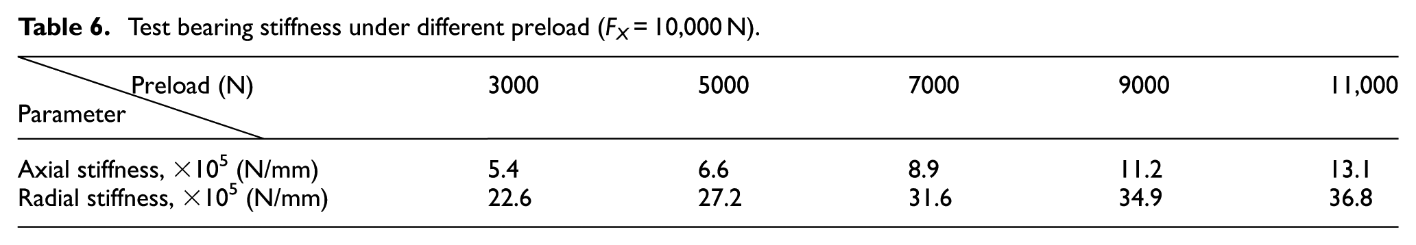
As shown in Table 6 and Figure 21, when the radial load FX = 10,000 N, with the linear increase of the preload from 3000 to 11,000 N, the total axial stiffness and total radial stiffness of the paired tapered roller bearings show a significant increase trend. which is consistent with the trend of the simulation results.
Test bearing stiffness under different preload (FX = 10,000 N).
Bearing stiffness under different preloads (FX = 10,000 N).
As shown in Table 7, when the radial load FX = 12,000 N, with the linear increase of the preload from 3000 to 11,000 N, the axial stiffness and radial stiffness of the first row of the paired tapered roller bearing show a significant increase trend. The axial stiffness and radial stiffness of the second row showed a significant decreasing trend. However, the total axial stiffness and total radial stiffness of the paired tapered roller bearing show an increasing trend, as shown in Figure 22, this shows that the axial stiffness and radial stiffness of the first and second rows have changed. However, the total axial stiffness and total radial stiffness of the paired tapered roller bearings show an increasing trend.
Simulation of bearing stiffness under different preloads (FX = 12,000 N).

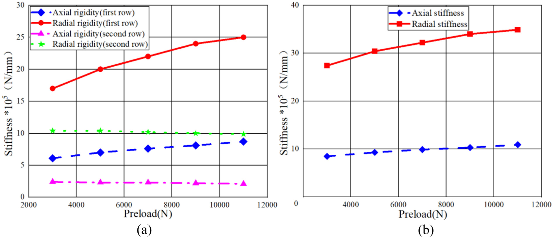
Bearing stiffness under different preloads (FX = 12,000 N). (a) Schematic diagram of stiffness change of each row of paired bearings. (b) Schematic diagram of total stiffness change of paired bearings.
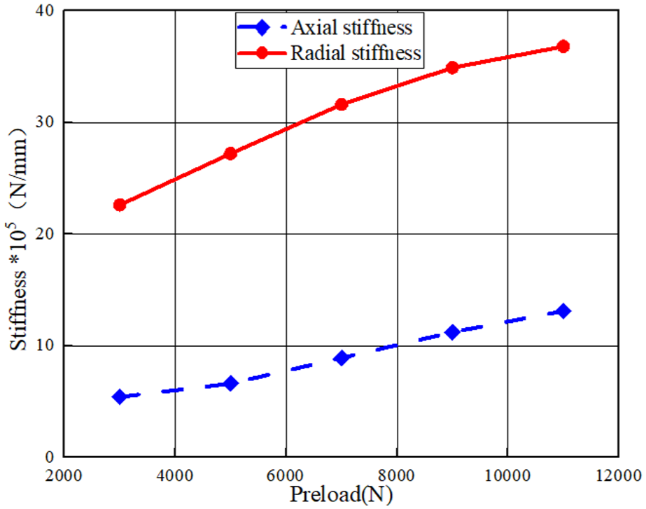
As shown in Table 8 and Figure 23, when the radial load FX = 12,000 N, with the linear increase of the preload from 3000 to 11,000 N, the total axial stiffness and total radial stiffness of the paired tapered roller bearings show a significant increase trend. which is consistent with the trend of the simulation results.
Bearing stiffness under different preloads (FX = 12,000 N).
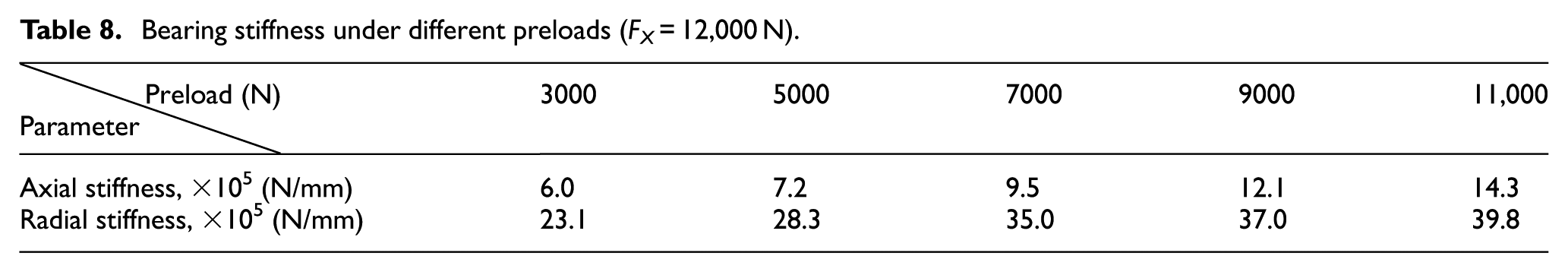

Bearing stiffness under different preloads (FX = 12,000 N).
As shown in Table 9, when the radial load FX = 14,000 N, with the linear increase of the preload from 3000 to 11,000 N, the axial stiffness and radial stiffness of the first row of the paired tapered roller bearing show a significant increase trend. The axial stiffness and radial stiffness of the second row show a decreasing trend. However, the total axial stiffness and total radial stiffness of the paired tapered roller bearings show an increasing trend. As shown in Figure 24, this shows that although the axial stiffness and radial stiffness of the first and second rows have their changes, the total axial stiffness and total radial stiffness of the paired tapered roller bearings show an increasing trend.
Simulation of bearing stiffness under different preloads (FX = 14,000 N).


Bearing stiffness under different preloads (FX = 14,000 N). (a) Schematic diagram of stiffness change of each row of paired bearings. (b) Schematic diagram of total stiffness change of paired bearings.
As shown in Table 10 and Figure 25, when the radial load FX = 14,000 N, with the linear increase of the preload from 3000 to 11,000 N, the total axial stiffness and total radial stiffness of the paired tapered roller bearings show a significant increase trend. which is consistent with the trend of the simulation results.
Bearing stiffness under different preloads (FX = 14,000 N).


Bearing stiffness under different preloads (FX = 14,000 N).
It can be seen from the simulation data that the axial stiffness and radial stiffness of the first row increase with the increase of axial preload from 3000 to 11,000 N when the radial load of the paired tapered roller bearing is constant. However, due to the face-to-face installation of the bearing, the force of the second row is small, so the axial stiffness and radial stiffness of the second row have a slight downward trend, and the stiffness of the second row is lower than that of the first row. However, the overall stiffness of the paired tapered roller bearing is bound to increase gradually.
From the above diagram, it can be seen that the bearing’s axial and radial stiffness still show a gradual increase when the load is applied to the rolling bearing’s dynamic stiffness test bench under the same working conditions as the simulation. The axial stiffness is always smaller than the radial stiffness, which is consistent with the actual working conditions. At the same time, it can also verify the correctness of the simulation model.
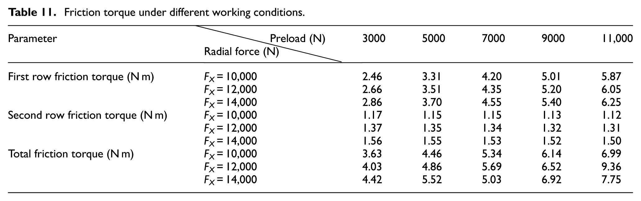
As shown in Tables 11, 12, and Figure 26, it can be seen from the above figure that the load of the same working condition as the simulation is applied on the dynamic stiffness test bench of the rolling bearing. When the other conditions of the test bench remain unchanged, and only the axial preload is changed, the friction torque of the whole machine still shows a gradual increase with the increase of the axial preload. The variation law and the torque of the whole machine under three different radial loads are almost the same, which proves that the variation amplitude of the friction torque of the whole machine caused by the load change is small, which is consistent with the actual working conditions and can also verify the correctness of the simulation model.
Friction torque under different working conditions.
The torque of the whole test bench under different working conditions.

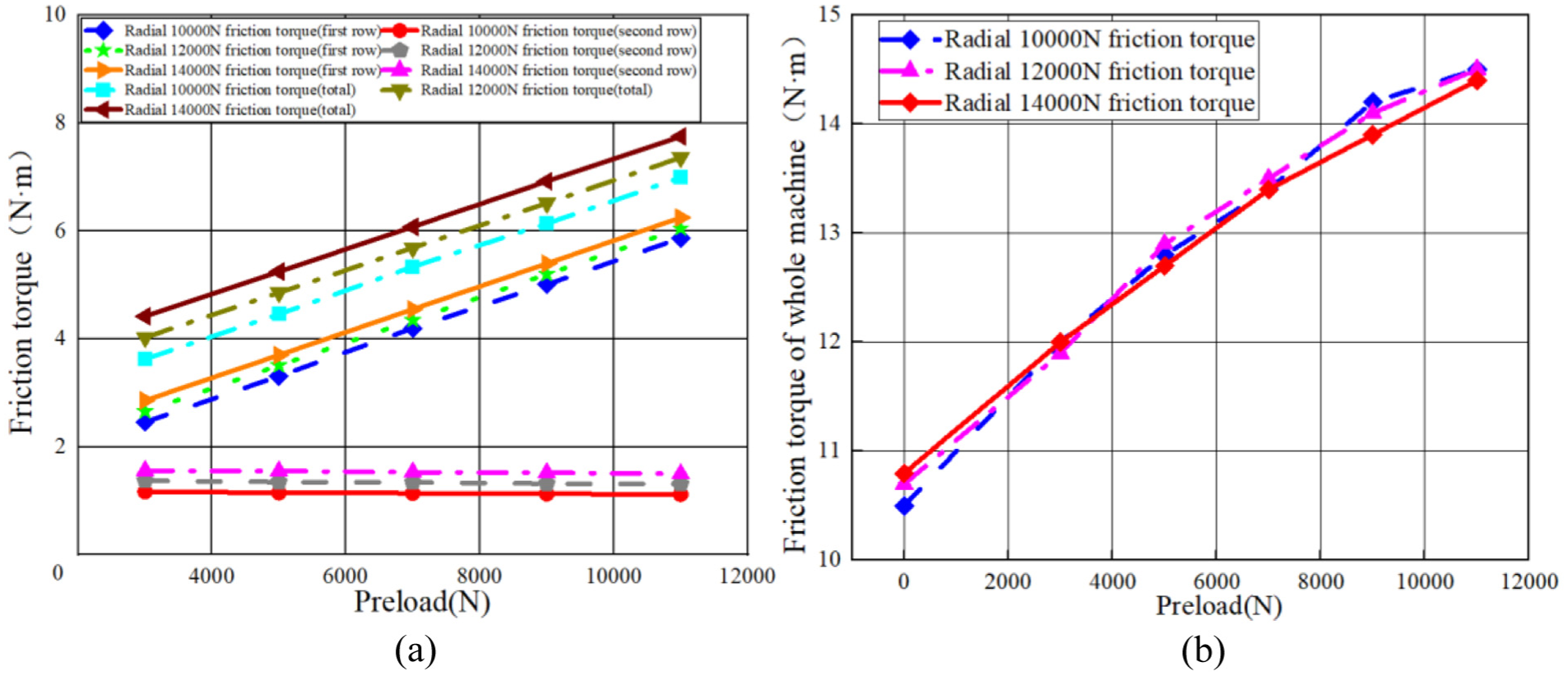
Simulation under different working conditions and friction torque of test bench. (a) The simulation relationship of the friction torque of the paired bearing. (b) The experimental relationship of the friction torque of the whole machine.
Conclusion
In this paper, the influence of assembly and adjustment parameters on the service characteristics of paired tapered roller bearings is studied. The law of multi-assembly and adjustment conditions from light preload to heavy preload and small interference to large interference is studied with the determined working conditions and speed. From theoretical calculation and simulation analysis to final experimental verification, the service performance of the bearing is fully explained. The change law of the adjustment parameters is as follows:
As the preload increases, the absolute value of the bearing clearance gradually rises, although the rate of increase progressively diminishes. The contact force between the rolling elements and both the raceway and the shoulder remains nearly uniform. Furthermore, the stiffness and friction torque of the bearing also steadily increase with the rising preload, while the friction torque of the second row of bearings consistently remains lower than that of the first row.
As the preload increases, the minimum oil film thickness of both the inner ring and raceway of the first column bearing, as well as that of the outer ring and raceway, gradually decreases. However, for the second column bearing, the minimum oil film thickness of the inner ring and raceway initially increases before subsequently decreasing. Regarding lifespan, the corrected lifespan of the first column bearing diminishes with increasing preload, whereas the corrected lifespan of the second column bearing exhibits a trend of first increasing and then continuously decreasing as preload increases.
With the increase in the interference, the radar chart formed by the full-cycle contact load shows a flat trend, and the maximum contact load between the roller and the raceway shows a decreasing trend. The stiffness of the first row of the bearing shows a decreasing trend, but the axial stiffness decreases significantly. The axial stiffness of the second row shows a slight increase trend, the radial stiffness shows a decreasing trend, and the change amplitude is small. The friction torque shows a gradual increase trend, and the friction torque of the second row is always smaller than that of the first row.
As the interference increases, the minimum oil film thickness of the inner ring and raceway of the first row of bearings, as well as that of the outer ring and raceway, progressively decreases. In contrast, the minimum oil film thickness of the inner ring and raceway of the second row initially increases before subsequently decreasing. Regarding bearing life, the corrected lifespan of the first row of bearings gradually diminishes with increasing interference. Conversely, the lifespan of the second row of bearings first increases and then decreases as the interference rises.
Footnotes
Handling Editor: Hui Ma
Funding
The authors disclosed receipt of the following financial support for the research, authorship, and/or publication of this article: We acknowledge the support of the Guangdong Basic and Applied Basic Research Foundation grant number (2021A1515110038) and Ji Hua Laboratory Program grant number (X220951UZ230). Our sincere gratitude goes to the reviewers for their insightful and constructive feedback, which has significantly enhanced the quality of this paper.
Declaration of conflicting interests
The authors declared no potential conflicts of interest with respect to the research, authorship, and/or publication of this article.