
Abstract
Efficient measurement of linear motion axes’ angular error is an important way for machine tool processing error traceability and accuracy improvement, and inertial measurement technology provides a new means for efficient measurement of machine tools’ angular error. At present, the commonly used test piece processing, optical measurement, level measurement, and other angular error measurement methods, there are problems such as long measurement time, complex installation and debugging, in-complete measurement of angular error items. For this reason, this paper introduces the efficient on-machine measurement method and device for linear motion angular error of CNC machine tools. Using a three-axis gyroscope to measure the angular velocity data in the three directions of linear motion, the angular error in the time domain is obtained by band reject filtering, one-time time integration, and integral cumulative deviation removal. The device is applied to two vertical machining centers to measure the angular error of linear feed axis in this paper. The results show that the three angular errors of each linear feed axis can be obtained within 4 min from the installation and commissioning of the device to the completion of the test, while it takes more than 30 min to use a laser interferometer under the same test conditions. In terms of measurement accuracy, the deviation of the measurement results of the Inertial Measuring Equipment compared with the laser interferometer is controlled within 1 arcsec.
Introduction
Linear motion axes are used to position machine components carrying tools and workpieces to a desired position. 1 Geometric errors in the linear axes affect the accuracy of the linear motion of these machine components, which in turn affects the quality and productivity of the workpiece. Geometric errors in the linear axes of a machine tool include three angular errors (pitch angle error, yaw angle error, roll angle error) and three linear errors (positioning error, straightness error in the horizontal plane, straightness error in the lead plane).
The superposition of machine tool angular and linear errors can easily cause different positioning accuracy, straightness, and squareness of the same linear axis at different positions in the machine tool workspace. As shown in Figure 1(a), due to the yaw angle error of the linear axis under test, the positioning error measured at position A of this linear axis is different from the positioning error measured at position B. This will result in the positioning accuracy of the Y motion axis being unqualified at position B even after the positioning accuracy of the Y motion axis has been qualified at position A by pitch compensation. As shown in Figure 1(b), the measured straightness at different positions is different due to the roll angular error of the linear axis guideway under test. It can be seen that the superposition of angular and linear errors can lead to difficulties in meeting the geometric accuracy requirements of linear axes at all spatial positions.

(a) Pitch angle affects positioning accuracy and b) roll angle affects straightness.
At present, there are a number of machine tool geometric error measurement technology and devices that can synchronize the measurement of angular error and linearity error in the world. 2 The American API company’s XD Laser 3 and the British Renishaw company’s XM-60 4 are both multi-beam laser interferometers, can realize the machine tool linear axis positioning error, straightness error, and angular error six geometric error measurement synchronization based on the laser interference principle. Compared to laser interferometers for single error measurements, multi-beam laser interferometers are much less complex to set up and adjust to light. Laser tracking instrument can dynamically track the receiver’s spatial three-dimensional position changes,5,6 its measurement efficiency and long-term stability is better than the laser interferometer, but the laser tracking instrument measurement accuracy is not as good as the laser interferometer. For example, the system accuracy (MPE) of the AT960-SR laser tracker from Leica, Switzerland, is 15 μm + 6 μm/m. 7 To further improve the measurement accuracy, multiple laser trackers are required for multilateral measurement. 8 Specimen machining test is a low-cost machine tool accuracy testing program 9 but the machining error reflects a combination of geometric error, process error, control error, and other types of errors, and it is necessary to use the typical characteristics of the part to identify individual errors one by one, such as the Chengfei “S” specimen, 10 and the angular error of the test efficiency and identification accuracy is low.
Inertial measurement provides a new way for the simultaneous measurement of angular error and linear error of machine tools. Inertial measurement mainly uses inertial sensors (including acceleration, angular velocity sensors, and their multi-axis combination of inertial measurement unit (IMU), etc.) to realize the target quantity measurement. 11 The precise full-degree-of-freedom position of the target is obtained by integrating the measured acceleration and angular velocity. This technique is often used in the fields of weapon guidance, aerospace, vehicle-mounted mobile mapping, bridge detection, and pedestrian navigation.12–15 Sato et al.16,17 from Kobe University, Japan, used acceleration sensors to measure the spindle trajectory of a CNC machine tool, and compared with the reference values to prove that acceleration sensors are good for elliptical trajectory measurement on machine tools. Vogl et al.18–20 measured the acceleration and angular velocity signals of the carrier based on the inertial measurement unit, and then integrated to calculate the linear and angular error information. Vogl et al. realized the simultaneous measurement of micro meter-level straightness error and arcsecond angular error based on the fusion of multi-frequency band data by repeatedly measuring the spatial low-frequency error under high-speed motion, the spatial medium frequency error under medium-speed motion, and the spatial high-frequency error under low-speed motion of the machine tool. Wang et al. 21 formed the inertial data spatiotemporal consistency guarantee technology for machine tool error measurement. However, inertial measurement technology has not begun to be widely used in the geometric error measurement of CNC machine tools. Machining accuracy of high-end CNC machine tools is usually in the μm and arcsec level at present,22–24 and the reason why this technology stays in the laboratory research stage is that the inertial measurement accuracy does not satisfy the conditions of the high accuracy of CNC machine tools.
For this reason, this paper introduces an efficient on-machine measurement device for linear motion angular error of CNC machine tools, which measures the angular velocity data in three directions of the linear motion of the motion axis by means of a three-axis gyroscope, and obtains the angular error in the time domain through band reject filtering (A filtering method that allows most frequency components to pass through while attenuating certain ranges of frequency components to extremely low levels), one-time integration of time, and removal of the cumulative deviation of integration. In this paper, the device is applied to the angular error measurement of linear feed axis of two vertical machining centers and compared with the laser interferometer measurement results. The results show that the method proposed in this paper obtains sufficient measurement accuracy in a very small amount of time and greatly improves the measurement efficiency.
Inertial measurement principle for angular errors in linear motion
The linear motion axis has angular errors in three directions, that is, pitch, yaw, and roll angular errors. According to the basic idea of Fourier transform, the angular error signal can be expressed as the sum of n kinds of sinusoidal signals with different amplitudes and frequencies.

where x is the coordinate position of the linear motion axis,
The angular velocity measured by the gyroscope is in the time domain and can be expressed as the sum of m sinusoidal signals of different amplitudes and frequencies:
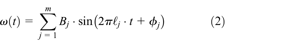
Where t is the measurement time,
Angular error inertial measurement is the measured

where
According to equations (1)–(3), the simplest way to convert the time-domain angular data
Linear motion of the coordinate position x and time t is a one-to-one correspondence, according to the formula (3), can be integrated after the time domain of the angular data, converted to the spatial dimension of the angular data

where K is the conversion factor from time frequency to space frequency.
The angular velocity signal measured under a certain uniform motion has both high frequency and low frequency signals, therefore, a band-pass filter is used to filter out the noise signal.
Item

The upper and lower cutoff frequencies
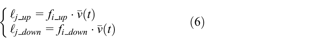
This cutoff frequency changes dynamically with the linear motion feed rate.
Integrating once for the angular velocity gives the angular error in the time domain:

where
The trend term where the cumulative deviation of integration is nonlinear can be expressed as

Highly efficient on-machine measurement device for angular errors in linear motion
Hardware system development
To accurately and efficiently obtain the machine tool linear axis angular error, the performance parameters and external dimensions of gyroscope need to be given particular attention. Since the angular error of a linear axis of a machine tool is a spatial error with a small amplitude that changes frequently, and since the angular velocity signal generated by the angular error has a very small amplitude, the choice of gyroscope should be used when selecting high-sensitivity, high-precision, low-noise, and high sampling frequency gyroscope. Part of the parameters of the gyroscope as shown in Table 1.
Gyroscope partial parameters.

In order to facilitate the collection of machine tool linear axis motion data, the three gyroscopes are assembled orthogonally in an aluminum alloy box, the side of the heat sink holes to reduce the impact of temperature on the gyroscope data drift, the bottom of the open ellipse in order to be fixed in the machine tool table with T-slot bolts, the three-dimensional diagram of the on-machine measurement device and the assembly of the physical drawing shown in Figure 2.

(a) Three-dimensional drawing and (b) actual assembly figure.
Software system development
This article uses MATLAB’s App Designer function to develop a data collection module. MATLAB has significant advantages in the field of signal processing: it provides rich built-in functions and toolboxes (such as Signal Processing Toolbox), supporting fast algorithm development and simulation; The MATLAB App Designer feature is a new generation of interactive application development tool that integrates visual interface design and MATLAB script programming functions, supporting the quick construction of user interfaces through drag and drop components. The software interface development of the experimental system mainly consists of two parts: The interface of the data acquisition module is shown in Figure 3(a), which mainly involves the configuration of sensor parameters and the input of experimental information, as well as sending a gating signal to the gyroscope, that is, communicating with the gyroscope and reading the original hexadecimal data; The interface of the data processing module is shown in Figure 3(b). This module is mainly responsible for converting the gyroscope angular velocity into measurement angle error, including data preprocessing, integration accuracy guarantee algorithm, measurement error image visualization and processing, and other functions.

(a) Data acquisition interface and (b) data processing interface.
Efficient on-machine measurement test for linear motion angular error
Test-related information
Test verification in the two vertical machining center machine tool X, Y linear feed axis, the comparison instrument selection of British Renishaw laser interferometer XM-60, the test machine specific information shown in Table 2, the comparison test instrument information shown in Table 3, the test site shown in Figure 4.
Test machine information.

Test equipment information.

A: displayed error reading; M: distance measurement in meters

The on-machine measurement site consists of two machines: (a) machine 1 and (b) machine 2.
Test flow
Before the test, ensure that the machine is shut down for more than 5 h, to ensure that the machine is in a state of uniform temperature distribution, to avoid the impact of thermal errors. The specific test process is as follows:
(1) Instrument installation and commissioning: install and commission the laser interferometer XM-60 and inertial measurement device, to ensure that the two measurement axes coincide, respectively, to measure the X, and Y axes of the two machine tools, as shown in Figure 5;
(2) Measure the angular accuracy of the machine tool linear axis in a uniform state round trip once again, the laser interferometer XM-60 data acquisition mode is set to time sampling, in this movement process, XM-60 and inertial measurement device automatically feedback measurement data;
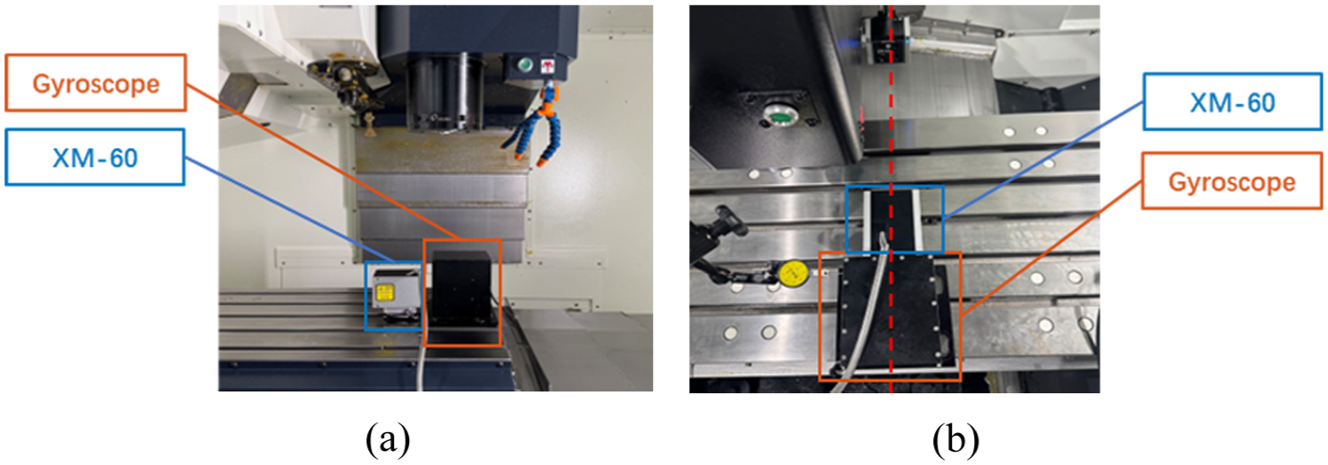
Two inertial measurement unit and XM-60 mounting positions include: (a) X-axis test and (b) Y-axis test.
Measurement results
The X and Y axes of two vertical machining centers were tested according to the test procedure in section “Test flow,” and the test comparison results are as follows:
Machine tool 1
(1) X-axis test results:
(2) Y-axis test results:
(3) Time taken from installation to completion of measurement:
Machine tool 2
(1) X-axis test results:
(2) Y-axis test results:
(3) Time taken from installation to completion of measurement:
Analysis of test results
As can be seen from Figures 6 to 9, the trend of change in the measurement data and amplitude size of the inertial measurement device and the laser interferometer XM-60 are basically the same. The sampling frequency of the new measurement method is 100 times that of the laser interferometer, and the measurement data contain more information about the change, which is especially advantageous in the measurement of high-frequency errors. From Tables 4 and 5, it can be seen that, in terms of the time used to measure an axis, the laser interferometer measurement needs to calibrate the laser and mirror position, the difficulty of debugging the instrument depends on the proficiency and luck of the test personnel, so the laser interferometer measurement of each axis requires at least 30 min. While the inertial measurement device has no operation threshold, the installation and measurement process is easier. The time to measure each axis can be controlled within 4 min, which effectively improves the measurement efficiency.

Comparison of three angular error measurements in the X-axis of machine 1: (a) roll angle, (b) pitch angle, and (c) yaw angle.

Comparison of three angular error measurements in the Y-axis of machine 1: (a) roll angle, (b) pitch angle, and (c) yaw angle.

Comparison of three angular error measurements in the X-axis of machine 2: (a) roll angle, (b) pitch angle, and (c) yaw angle.

Comparison of three angular error measurements in the Y-axis of machine 2: (a) roll angle, (b) pitch angle, and (c) yaw angle.
Machine 1 measurement time.

Machine 2 measurement time.

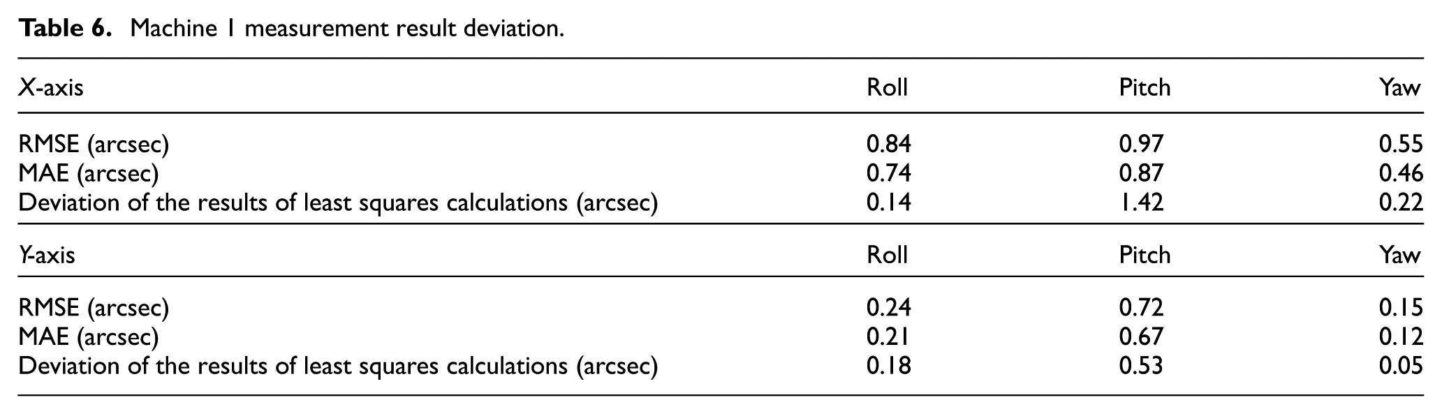
In order to further illustrate the measurement accuracy of the inertial measurement device, this paper adopts the root mean square error (RMSE), the mean absolute error (MAE), and the deviation of the measurement results calculated by the least squares method to quantify the difference between the measurement data of the inertial measurement device and the laser interferometer. The quantitative deviation degree of the two measurements is shown in Tables 6 and 7.
Machine 1 measurement result deviation.
Machine 2 measurement result deviation.

Analysis of Tables 6 and 7 shows that the MAE and RMSE between the measurement data of the gyroscope and the laser interferometer are basically within 1 arcsec, of which only in the measurement of the X-axis of machine tool 2 when the measurement results are unsatisfactory. From Figure 7, it can be seen that the X-axis angular error data of machine tool 2 has a stronger degree of oscillation and a faster rate of change, which leads to a large difference in the repeated measurement results of the two measuring instruments (more data are not shown in this paper), but the overall trend and size are consistent. This further verifies that the accuracy of the new measurement method proposed in this paper meets the requirements of machine tool accuracy testing, and has a higher sampling frequency compared with the laser interferometer measurement method, which is more capable of restoring the detailed components of the machine tool angular error. In addition, due to the large gap between the sampling frequency of the two measuring instruments, the two produce large differences locally, the RMSE and MAE are affected by the residuals of the outliers. This paper also adopts the least squares method to calculate the deviation of the angular error results of the laser interferometer and gyroscope measurements. Analyzing Tables 6 and 7 shows that using the least squares method to calculate the angular error measurement results of the gyroscope and the laser interferometer shows that the two measurement results are very close. In the 12 groups of angular data measured, there are 3 groups of data deviation more than 0.5 arcsec, of which only 1 group of data deviation more than 1.0 arcsec, and the rest of the 9 groups of data deviation are within 0.5 arcsec. Therefore, it can be concluded that the new method of inertial measurement of angular error proposed in this paper fully meets the demand for linear axis measurement accuracy of machine tools.
Conclusions
Aiming at the low efficiency and high cost of the existing machine tool linear axis angular error measurement methods, this paper proposes a new measurement method based on the integration of angular velocity, and develops inertial measurement device hardware and software system. Test trials are conducted on a total of four linear motion axes of two machine tools and compared with Renishaw XM-60 measurement results. In 12 groups of test results, inertial measurement device and XM-60 measurement results are basically within 0.5 arcsec deviation, fully meet the needs of machine tool linear axis angle accuracy measurement, and more advantageous in terms of efficiency and cost.
The main contributions of this paper are as follows: (a) provide new ideas for machine tool accuracy measurement (b) provide a new quality production tools, reduce the technical threshold of machine tool accuracy testing, improve the testing efficiency. The new measurement method proposed in this paper provides the possibility of online measurement in machine tool processing, and provides a convenient means for the implementation of CNC machine tool accuracy maintenance and error compensation.
Although this study has achieved the above results and verified the feasibility of the measurement method studied in this paper through experiments, there are still areas that need improvement:
(1) Further consideration needs to be given to the impact of temperature on the measurement accuracy of in machine measuring devices. The measurement method proposed in this article can obtain machine tool errors in a short period of time, but the influence of environmental temperature changes on accuracy in long-term measurements still needs to be considered.
(2) The accelerometer can be integrated into the in machine measurement device to study the method of converting acceleration into linear positioning error and straightness error of the machine tool. By installing and measuring all six geometric errors of the linear axis at once, the testing efficiency can be further improved.
(3) The accuracy of inertial navigation systems involves many factors, such as the impact of pose changes during device movement on measurement results, which requires further research to reduce the influence of experimental conditions on measurement accuracy.
Footnotes
Handling Editor: Chenhui Liang
Author contributions
All authors participated in writing and reviewing, editing the manuscript, analyzing the data, obtaining resources, data curation, and reviewing drafts of the paper. All authors have read and agreed to the published version of the manuscript.
Funding
The author(s) disclosed receipt of the following financial support for the research, authorship, and/or publication of this article: The authors gratefully acknowledge the support from two programs of the National Natural Science Foundation of China (U24B6006 and U22B2085).
Declaration of conflicting interests
The author(s) declared no potential conflicts of interest with respect to the research, authorship, and/or publication of this article.