
Abstract
During motor operation, variations in motor parameters lead to model mismatch, while unknown internal and external disturbances degrade control performance, resulting in poor disturbance rejection and robustness. To address this issue, this study analyzes the impact of parameter variations on current tracking performance and proposes a single-degree-of-freedom active disturbance rejection control (SDF-ADRC) method incorporating dual filters for current regulation. The approach extends the total disturbance of the error dynamic equation into a new state, constructs an extended state observer and control law, and evaluates the disturbance rejection capability of the model through frequency-domain analysis. Furthermore, to reduce the steady-state error in disturbance estimation, an adaptive notch filter and a first-order low-pass filter are designed, along with a parameter tuning procedure. Experimental results demonstrate that compared with PID method and SDF-ADRC method, the proposed method averagely reduces 55.13%, 26.97%, 30.02% and 35.29%, 20.24%, 20.08% respectively in the speed absolute deviation, THD of d, q axis current, which exhibits superior disturbance rejection, enhanced robustness, reduced output pulsation, and improved dynamic performance.
Keywords
Introduction
As a core component of modern high-energy propulsion systems such as aircraft catapults and high-speed trains, electromagnetic launch systems require driving devices with high power density, fast transient response, and operational stability. The permanent magnet synchronous motor (PMSM), known for its high torque density, superior efficiency, and outstanding dynamic performance, has become a key technology in electromagnetic launch applications.1,2 The current loop, serving as the inner control loop of the PMSM, forms the foundation of the control system. However, the PMSM is a complex system characterized by multivariable coupling, strong nonlinearity, and time-varying parameters. In missile electromagnetic launch scenarios, harsh environmental conditions and complex operating modes further exacerbate parameter variations, degrading control performance. Thus, advanced control strategies are essential to enhance motor stability and operational efficiency.3,4
Traditional PMSM current control methods primarily fall into two categories: vector control and direct torque control (DTC). Vector control decouples the three-phase stator current into two orthogonal components—the torque-generating current (q-axis) and the flux-generating current (d-axis)—enabling independent control of torque and magnetic flux. Its key advantage lies in precise coordinate transformation and closed-loop regulation, which grants the motor dynamic response capabilities comparable to those of DC motors. However, vector control heavily depends on motor parameters and requires complex coordinate transformations and PI regulator design, increasing system complexity and tuning difficulty. 5 Direct torque control, on the other hand, bypasses coordinate transformations by directly regulating stator flux linkage and electromagnetic torque. It selects optimal voltage vectors to rapidly adjust torque and flux, simplifying control structure and improving dynamic response. Since it eliminates current decoupling, DTC exhibits lower sensitivity to motor parameter variations and maintains superior torque control performance even at low speeds. However, DTC suffers from relatively high torque ripple, and its flux observation accuracy at low speeds is susceptible to stator resistance variations. Consequently, supplementary compensation techniques are often required in practical applications to enhance steady-state performance.6,7
For the interference problems of external and internal disturbances, many scholars adopt nonlinear controllers to solve them, such as adaptive robust control, neural network control, and robust control based on estimating the upper bound of interference, etc. Dong et al. 8 studies the high-performance motion control of valve-controlled hydraulic actuators under input saturation and modeling uncertainty. A continuous differentiable static friction model is constructed, and an adaptive robust design is adopted to deal with modeling uncertainties. To address the issue of input saturation, an embedded anti-saturation module optimization controller with a dual regulation mechanism was designed to ensure the stability and performance of the system. The relevant conclusions were analyzed and verified by Lyapunov, and the effectiveness of the method was confirmed through simulation. The actual control system is confronted with internal and external interferences as well as various types of constraints, and it is difficult for the existing controllers to take them all into account. Yang et al. 9 proposes a neural adaptive learning algorithm for constrained nonlinear systems that require interference suppression. By designing performance functions and time-varying barrier Lyapunov functions, output performance specifications and state constraints are achieved. Combined with neural networks and observers, interference and uncertainty are estimated and compensated online. The filter is introduced to estimate the virtual control law, and the controller is synthesized based on the filter values. The auxiliary system is utilized to compensate for the filter error and input saturation. Ultimately, the closed-loop stability was strictly guaranteed, and the performance of the algorithm was verified by practical applications.
In recent years, to enhance the control performance of PMSMs and address issues such as dependency on mathematical motor models, sensitivity to disturbances, and parameter variations, researchers worldwide have proposed various advanced control strategies, including sliding mode control, proportional resonant control, model predictive control, and active disturbance rejection control.
In the field of PMSM current control, Active Disturbance Rejection Control (ADRC) has been widely recognized as an efficient solution due to its outstanding disturbance rejection capability and simplified parameter tuning. It effectively handles complex disturbances such as parameter perturbations, abrupt load variations, and nonlinear friction. The core of ADRC lies in its Extended State Observer (ESO), which provides real-time and accurate estimation of the total system disturbances. By incorporating a nonlinear feedback law, ADRC dynamically optimizes the control input, thereby overcoming inherent limitations of conventional control methods—including integral saturation and parameter sensitivity. To address the resonance issues induced by LC filters between voltage source inverters and cables—which degrade dynamic response and reduce system stability when control gains increase—Li et al. 10 proposes a cascaded model-assisted ADRC strategy with fast and robust dynamic performance. The proposed strategy leverages a Modified ESO to treat known system resonance characteristics as the derivative of total disturbances for compensation, significantly reducing reliance on high bandwidth requirements while accelerating settling time. Furthermore, control parameters are systematically designed based on precise transfer function derivations and frequency-domain specifications to ensure robust performance. Experimental results demonstrate that this method enhances PMSM current control dynamics substantially, achieving over 72% reduction in settling time compared to existing approaches while exhibiting markedly improved robustness. To address the stringent requirements for safety, stability, and dynamic performance of PMSMs under complex operating conditions, as well as the limitations of conventional ADRC (including parameter sensitivity and insufficient disturbance rejection capability caused by nonlinear error attenuation functions), Wang et al. 11 proposes a novel deep reinforcement learning (DRL)-based ADRC strategy. The proposed approach first establishes a flux-weakening control model to adapt to the high-speed flux-weakening region characteristics of PMSMs. Subsequently, a DRL-based ADRC framework is constructed, where a deep neural network replaces the traditional control law and integrates a Markov decision process. Combined with the twin delayed deep deterministic policy gradient algorithm, the DNN parameters are optimized to effectively reduce the number of control parameters and suppress jitter. Simulation and experimental results demonstrate that this method achieves 50% reduction in control law complexity, significant improvement in system dynamic performance, and enhanced robustness under varying operating conditions. To address critical limitations of conventional ADRC – including slow disturbance observation, significant speed fluctuations under load variations, and steady-state accuracy degradation caused by unmodeled periodic current disturbances – Guo et al. 12 proposes a multi-dimensional enhancement strategy: A third-order ESO with proportional-integral disturbance update law is designed to accelerate disturbance estimation, significantly improving both tracking performance and disturbance rejection capability; Real-time q-axis current measurements are utilized as feed forward compensation terms, effectively suppressing speed fluctuations induced by abrupt load changes; A nonlinear switching function with bounded gain and IIR low-pass filter are developed to precisely attenuate unmodeled dynamic disturbances, particularly periodic components. The proposed method demonstrates superior performance and robustness in complex operating conditions through comprehensive simulation and experimental validation. To address the inherent trade-off between disturbance robustness and measurement noise sensitivity in conventional ESO-ADRC, Cao et al. 13 proposes a novel variable-structure ADRC framework with dual-layer interconnected observers. This method effectively strikes a balance between disturbance rejection performance and noise suppression by designing a variable-structure extended state observer with two-stage interconnected observers and adding extended disturbance differentials to achieve a higher level of disturbance estimation. The results show that the strategy has significant advantages in both interference suppression and noise robustness, and its feasibility and effectiveness have been verified through experiments.
Currently, both academia and industry predominantly focus on feedback signal-based ADRC, typically classified as a two-degree-of-freedom (TDF) ADRC architecture. In recent years, an innovative single-degree-of-freedom (SDF) ADRC architecture has emerged, demonstrating the following distinctive advantages compared to conventional TDF ADRC: (1) It integrates the differential information of the reference signal into total disturbance estimation, effectively eliminating the need for explicit differentiation; (2) Its control mechanism is driven by the error between the reference signal and feedback signal, resulting in stronger compatibility with existing industrial controllers and greater potential for widespread practical deployment. Through comparative analysis, Liu et al. 14 confirmed that while inheriting the advantages of TDF ADRC, the SDF architecture also features simpler structure and more straightforward analysis. However, constrained by the bandwidth limitations of the ESO, when observing disturbances such as inverter dead-time effects, permanent magnet flux harmonics, and current sampling errors, non-negligible steady-state errors persist between the estimated and actual disturbance values in SDF ADRC. This limitation partially restricts its ability to achieve perfect tracking of the reference speed.
To enhance the robustness of PMSM current against parameter variations and improve disturbance rejection for both known and unknown disturbances, this paper proposes a dual-filter-based SDF ADRC method. First, the sensitivity of PMSM current to parameter changes (e.g. resistance, inductance, and flux linkage) is analyzed. Then, the total system disturbance is extended into the error dynamic equation as a new state variable, establishing a SDF ADRC control model with frequency-domain-based anti-disturbance performance analysis. Subsequently, to reduce steady-state errors, an adaptive notch filter and a low-pass filter are designed, along with a detailed gain parameter tuning process. Finally, simulation and experimental results demonstrate that the proposed method achieves strong robustness and disturbance rejection, enabling fast dynamic response while reducing speed pulsation, current ripple, and buffeting.
The paper is structured as follows: Section “PMSM current loop parameter sensitivity analysis” analyzes the sensitivity of PMSM current to parameter variations. Section “Single-degree-of-freedom active disturbance rejection control model” develops the SDF-ADRC framework, including ESO and control law design, along with anti-disturbance performance analysis. Section “Single-degree-of-freedom ADRC control model with two filter” presents the adaptive notch filter and low-pass filter design, including gain parameter tuning. Section “Experimental verification” provides simulation and experimental validation. Section “Conclusion” concludes the paper.
PMSM current loop parameter sensitivity analysis
The mathematical model of the current inner loop of PMSM in the d-q rotating coordinate system is15–17


In the equation: u d and u q , i d and i q , ψ d and ψ q , L d and L q are the d-q axis voltage, current, flux linkage, and inductance respectively; R is the stator resistance; ω e is the electrical angular velocity; ψ f is the flux linkage of the permanent magnet. For the surface mount PMSM, L d = L q = L0.
Substituting equation (2) into (1) yields

According to equation (3), the stator current is selected as the state variable, resulting in

Rewrite equation (4) as


The continuous-time model equation (5) is discretized to obtain the state space model of the discrete-time system

In the equation:

In the actual algorithm, the parameters used in the model are the nominal values on the motor nameplate, and the predicted current is

In the equation: R0, L0, and ψ f 0 are the nominal values of the stator resistance, stator inductance, and permanent magnet flux linkage on the motor nameplate, respectively.
But in the actual control process, as the motor runs, the parameters of the motor will change, and the predicted current is

In the equation: R1, L1, and ψ f 1 are the actual values of the stator resistance, stator inductance, and permanent magnet flux linkage, respectively, when the motor is running.
Due to the influence of factors such as temperature rise and flux saturation, the nominal values on the motor nameplate may deviate from the actual values. Therefore, make the control voltage equation (11) equal, and obtain the relationship equation (12) between the actual predicted current and the nominal predicted current.


In the equation: ΔL = L1−L0;ΔR = R1−R0;Δψ f = ψ f 1−ψ f 0.
Since the sampling time T s is small enough, equation (12) is obtained by the z-transform
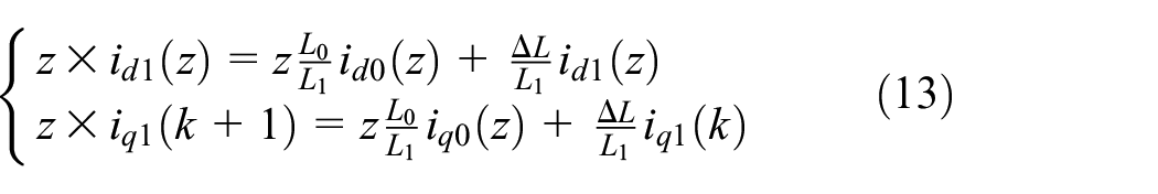
The transfer function between the actual value and the nominal value of the predicted current obtained from equation (14) is

In order to maintain the stability of the discrete system, the poles of the discrete system are all on the unit circle, that is, ∣L0/L−1∣ ≤ 1. When 0 ≤ L0 ≤ 2L, the system is in a stable state, but when the inductance value on the motor nameplate is greater than twice the actual inductance value, the system becomes unstable, generating oscillations and current statics.
As can be seen from equation (12), the d-axis current and q-axis current are symmetrical for the effect of parameter resistance and inductance mismatch. And the flux linkage mismatch only affects the q-axis current. As can be seen from Figure 1, the resistance mismatch has a smaller effect on the current, while the inductance and flux linkage mismatch have a larger effect. Figure 1 shows the relationship between current errors in the d-axis current, q-axis and resistance, inductance, and flux linkage mismatch at rated speed.

The relationship between d-q axis current error and the mismatch of resistance, inductance, and flux: (a) the relationship between d-q axis current error and the mismatch of resistance and inductance and (b) the relationship between q-axis current error and flux mismatch.
Single-degree-of-freedom active disturbance rejection control model
When considering parameter variations, the PMSM mathematical model becomes

Equation (15) is simplified to

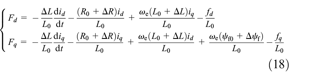
Taking the currents of the d, q-axis as the system output, the voltages of the d, q-axis as the system input, and the remaining terms as the sum of the known and unknown interference terms of the system, according to equation (16), the current control model of PMSM is obtained as18–20

In the equation: α d and α q are controller gains; F d and F q are the total disturbance of the system of the system on the d, q axis current, respectively; f d and f q are unknown disturbance on the d, q axis current, respectively.
Taking the design of the single-degree-of-freedom active disturbance rejection control (SDF-ADRC) for the d-axis current of the current loop as an example, the d-axis current error e d is defined:

Then:

Here, i dref represents the d-axis current reference value, F d represents the total disturbance of the d-axis current system, and f ed represents the total disturbance of the error dynamic equation, which consists of two parts: the total disturbance of the d-axis current system and the differential value of d-axis reference current.
For the error dynamic equation, the error e d reference value can be regarded as zero, so its control objective is to force the tracking error to approach zero by adjusting the stator voltage under disturbance conditions.
Expand the f ed to the new state, then:

In the equation, z ed is the differential value of the total disturbance of the error dynamic equation f ed , which is bounded.
The SDF-ADRC control model consists of two parts: one is the extended state observer design (ESO) and the other is the control law design.21–24
Extended state observer design
According to equation (21), the extended state observer of SDF-ADRC is designed as:

Where

In the equation, ω0 is the bandwidth of the ESO, and its value determines the response speed at which ESO estimates the disturbance.
Control law design
The control law of the SDF-ADRC model can be designed as25–27:
Here, K e is the bandwidth of the control law, whose magnitude directly determines the speed of the current dynamic response. Substitute equation (24) into equation (22).

It can be seen that if the ESO can accurately estimate the total disturbance, the current tracking error and its first derivative are zero, and then the output current loop controls the target: the output current accurately tracks the reference current.
Analysis of the anti-interference performance of the SDF-ADRC
Transfer function from actual disturbance to estimated disturbance according to equations (21)–(25):

and

It can be obtained:

It can be seen that the SDF-ADRC observes disturbance, which can detect disturbance in the current loop (such as in the form of parameter changes, load torque changes, etc.).
Further analysis of the anti-interference performance of the SDF-ADRC based on the Bode plot. According to equations (21)–(24), the transfer function of the SDF-ADRC is:

The disturbance transfer function of the SDF-ADRC current loop closed-loop system can be obtained as:

Figure 2 shows the Bode diagram of the disturbance transfer function of a SDF-ADRC current-loop closed-loop system. Here, K e is set to 50, and ω0 is set to 3K e , 5K e , and 7K e respectively to observe the filtering effect of the Bode plot. According to the Bode plot, the system has a strong attenuation effect on zero frequency, very low frequency, and high frequency attenuation signals, but a weak attenuation effect on medium and low frequency attenuation signals. While increasing the ESO bandwidth ω0 can improve the attenuation of medium and low frequencies disturbance to some extent, excessive ω0 may cause instability in the system.

The Bode diagram of the disturbance transfer function of SDF-ADRC.
Single-degree-of-freedom ADRC control model with two filter
Due to bandwidth limitations, there is a certain steady-state error between the estimated disturbance and the actual disturbance when ESO observes periodic disturbance (such as inverter dead time, magnet flux linkage harmonics, current sampling error in the form of sine waves), which means that the output speed cannot fully track the reference speed.1,28–30 To further improve the observation performance, a filtering processing module is introduced in the feedback loop of the current loop.

Here, i d represents the filtered d-axis current and i fd represents the unfiltered d-axis feedback current. k1 and k2 are adjustment factors, 0 ≤ k1, k2 ≤ 1, and to ensure that the feedback amplitude remains unchanged, k1 + k2 = 1.
Adaptive filters and low-pass filters
Due to the high harmonic generated by disturbances such as the dead zone of the PMSM inverter and the flux linkage of the motor’s permanent magnets, large tracking errors occur in the d, q-axis currents. In order to suppress the tracking error caused by the higher harmonics, an adaptive notch filter is used to suppress specific frequency components in the signal. N(s) represents the basic second-order notch with the gain parameter, and the basic second-order notch transfer function with e as input and y as output is:

Among them, í is the basic second-order notch filter gain parameter, adjusting the gain parameter will affect the notch filter bandwidth, thus changing the frequency selection characteristics of the notch filter. ω1 is the central frequency.
The output y of basic second-order notch filter is tracked to the input signal x in the form of unit negative feedback. The difference between the two is taken, and the error quantity δ is used as the input of the adaptive notch filter. Adaptive notch G trap (s) transfer function with δ as output and x as input.

In practical applications, there are certain fluctuations and interferences in speed and current. To improve the suppression performance and adaptability of the notch filter, the gain coefficient η can be dynamically adjusted according to the information of the error signal to adjust the bandwidth and convergence speed of the notch filter in real time.
The normalized least mean square (NLMS) algorithm is applied to the iterative update of the gain coefficient in the adaptive notch filter to achieve the purpose of normalizing the step size by the input signal power, avoiding the situation where the step size iteration is too large or too small under different power input signals. The influence of step size on the performance of the algorithm has been reduced, the stability and robustness of the algorithm have been improved, and the convergence speed is faster. Under the NLMS algorithm, the iterative rules of the gain coefficient are as follows:
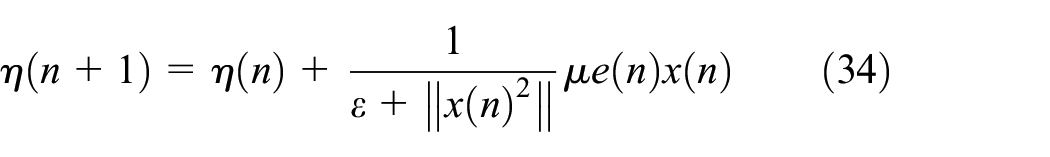
Among them: Where η(n) is the gain coefficient of the notch filter at the current moment; μ is the step size of the algorithm, that is, the learning rate; x(n) is the input signal of the notch filter at the current moment; e(n) represents the error signal of the unit feedback, e(n) = x(n)−y(n); ‖x(n) 2 ‖ is the power of the input signal x(n). The introduction of the normalization term 1/‖x(n) 2 ‖ reduces the influence of the learning rate μ on the algorithm under different power conditions. ε is taken as a positive constant to avoid zero in the denominator and ensure the stability of the algorithm.
The frequency-domain characteristic of the adaptive notch filter is shown in Figure 3. There is only a large amplitude attenuation at the notch frequency, and the amplitude remains largely unchanged in other frequency intervals.

The frequency-domain characteristics of the adaptive notch filter.
The low-pass filter G lpf (s) is used to filter out the higher harmonics in the current and the harmonics caused by the application error. In this section, the low-pass filter is used, and its transfer function is:

Where ω2 represents the cut-off frequency of the low-pass filter.
The k1 and k2 adjustment factors are determined
Combining the adaptive notch filter and the low-pass filter, the close-loop transfer function of the filter module is obtained as
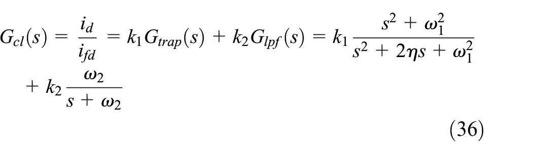
Considering that the current loop can track the current reference signal well under SDF-ADRC control. The close-loop transfer function of the d-axis current loop can be obtained:

Figure 4 shows the Bode diagram of the frequency-domain analysis of the control system. The adjustment factors k1 were set to 0.6, 0.7, 0.8, and 0.9 respectively to observe the filtering effect of the controller. As can be seen from Figure 4, this control system retains the unique advantages of the adaptive notch filter, generating significant attenuation at the center frequency, effectively suppressing the signal of this frequency, while maintaining the integrity of other signals. Due to bandwidth limitations, when ESO estimates disturbances, steady-state errors will occur at specific frequencies. Therefore, the setting of this control can effectively attenuate signals at specific frequencies, improve the observation performance of ESO, and reduce steady-state errors.

The Bode diagram of integrated two filters.
According to equation (37), plot the root trajectory of the parameters of k1 as shown in Figure 5. It shows that when k1 approaches 0, the system tends to be stable. Therefore, to improve the robustness of the system, it is recommended that k1 be around 0.8.

The root trajectory of the parameter k1.
The control structure of the SDF-ADRC with two filters method proposed in this paper is shown in Figure 6.

Control diagram of PMSM drive system integrating SDF-ADRC with two filters.
Experimental verification
The PMSM experimental platform mainly includes a real-time simulator, a research and development driver, a universal driver, a multi-functional acquisition card, and a motor-to-drag platform, as shown in Figure 7. The experimental platform is based on MATLAB/Simulink for designing the algorithm model of the servo control system, which can design the full loop controller for the outer loop of the speed, the inner loop of the current and the position loop of the controlled motor, providing support for the algorithm model to control the motor experiment. During the experiment, the dynamic characteristics, static characteristics, and nonlinear factors of the controller can be truly reflected, providing a verification environment for the development and debugging of the servo control system. The value of α d and α q can be set 4000.

The PMSM experimental platform.
The principle of the experimental platform is shown in Figure 8. First, on the development host side, the servo motor control algorithm was modeled using MATLAB/Simulink. After successful compilation, the embedded code was generated and downloaded to the real-time simulator for operation. The real-time simulator runs the real-time code of the servo motor algorithm model and is connected to the R&D driver through a multi-functional acquisition card to collect the phase current, bus voltage, and encoder signals of the driver in real time, and output three groups (a total of six channels) of inverter signals to directly control the conduction or cut-off of the insulated gate bipolar transistor in the circuit bridge of the R&D driver to achieve control of the servo motor. Meanwhile, the analog output card of the real-time simulator controls the general-purpose driver, allowing the load motor to apply torque to the servo motor, and the torque sensor collects the magnitude of the torque to test the control effect of the servo motor under constant or variable load conditions. PMSM test parameters are shown in Table 1.

PMSM experimental platform configuration and principle diagram.
PMSM parameters.

To verify the control performance of the method proposed in this paper, the PID method, the SDF-ADRC method, and the SDF-ADRC method with two filters are compared. The experiment is carried out under four working conditions:
Under the condition of adding the rated load, the speed varies in 1000 rpm→3000 rpm→1000 rpm. The speed tracking and the d, q-axis current tracking effects of the three methods are compared.
At the rated speed, the load torque varies in 0→3.18 N m→0. Compare the speed tracking and the d, q-axis current tracking effects of the three methods.
At the rated speed, the load torque variation and inductance variation are added, among which the inductance has become two times its original value. The speed tracking and the d, q-axis current tracking effects of the three methods are compared.
At the rated speed, add the load torque variation and flux linkage variation, among which the flux linkage becomes 0.5 times the original. Compare the speed tracking and the d, q-axis current tracking effects of the three methods.
Under the condition of speed variation
Figure 9 shows the comparison results of the speeds tracking of the three methods under the condition of speed variation. It can be known from the results in Figure 9 that when the rated load torque is added, the speeds of all three methods decrease. However, the speed decrease of the method proposed in this paper (SDF-ADRC + Two filters) is relatively small, while the speed decrease of the SDF-ADRC method and the traditional PID method is relatively large. When the speed changes from 1000 to 3000 rpm, the method proposed in this paper hardly causes overshoot and can track the speed change quickly. The other two methods cause a certain degree of overshoot and have a slower dynamic response in tracking the speed change. When the speed changes from 3000 to 1000 rpm, the method proposed in this paper can track the speed change quickly. In terms of tracking effect, the other two methods both show certain delays. Under the condition of speed variation, compared with the other two methods, the method proposed in this paper is less affected by interference when the rated load torque is added, has a smaller speed reduction, has strong robustness and anti-interference ability, and can quickly track the speed change with a faster dynamic response characteristic.
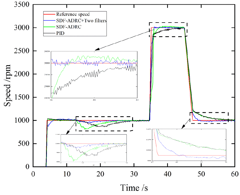
Under speed variation conditions, comparison of the speed tracking effects of three methods.
Figure 10 shows the comparison results of d-axis currents tracking of the three methods under the condition of speed variation. It can be known from the results in Figure 10 that certain ripple occurs in the d-axis current tracking of the three methods, and certain distortion occurs in the d-axis current of the traditional PID method. However, the total harmonic distortion (THD) of the method proposed in this paper is relatively small, reducing by 14.39% compared with the SDF-ADRC method and by 25.58% compared with the traditional PID method.
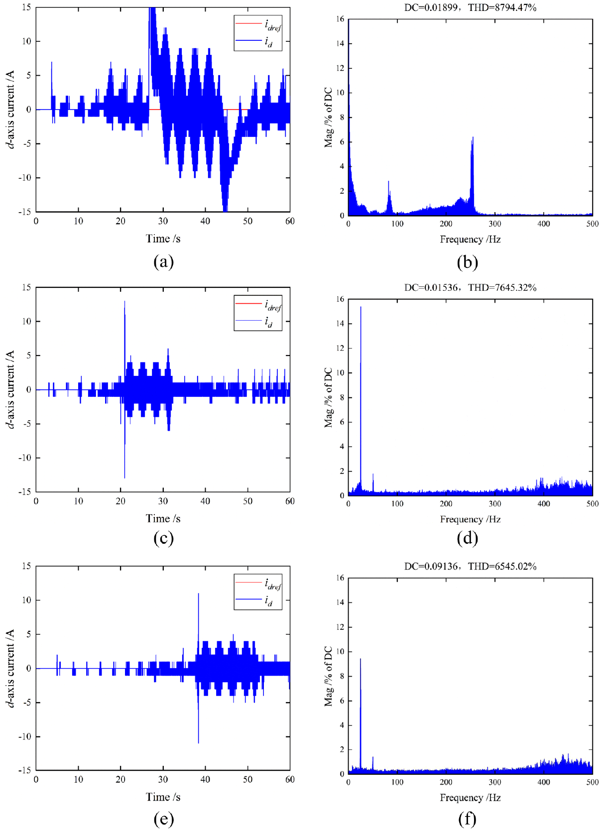
Under speed variation conditions, comparison of the d-axis current tracking effects of three methods: (a) the d-axis current tracking of PID method, (b) the d-axis current THD of PID method, (c) the d-axis current tracking of SDF-ADRC method, (d) the d-axis current THD of SDF-ADRC method, (e) the d-axis current tracking of SDF-ADRC with two filters method, and (f) the d-axis current THD of SDF-ADRC with two filters method.
Figure 11 shows the comparison results of the q-axis currents of the three methods under the condition of speed variation. It can be known from the results in Figure 11 that THD of the method proposed in this paper is relatively small, reducing by 9.26% compared with the SDF-ADRC method and by 16.18% compared with the traditional PID method. Under the condition of speed variation, compared with the other two methods, the current dynamic response of the d, q-axis proposed in this paper is faster, the current ripple and THD are smaller, and it has certain robustness and anti-interference ability.

Under speed variation conditions, comparison of the q-axis current tracking effects of three methods: (a) the q-axis current tracking of PID method, (b) the q-axis current THD of PID method, (c) the q-axis current tracking of SDF-ADRC method, (d) the q-axis current THD of SDF-ADRC method, (e) the q-axis current tracking of SDF-ADRC with two filters method, and (f) the q-axis current THD of SDF-ADRC with two filters method.
Under the condition of load torque variation
Figure 12 shows the speed tracking comparison results of the three methods under the condition of load torque variation. It can be known from the results in Figure 12 that when the load torque is added or removed, the speeds of all three methods fluctuate. However, the speed offset and overshoot of the method proposed in this paper are relatively small, while the speed changes of the SDF-ADRC method and the traditional PID method are relatively large. Moreover, the method proposed in this paper can quickly track the speed changes, while the dynamic responses of the other two methods in tracking speed changes are relatively slow. Compared with the other two methods, the method proposed in this paper has certain robustness and anti-interference ability under the influence of the dynamic change of load torque, with smaller speed fluctuation, capable of quickly tracking speed changes and having a faster dynamic response.

Under load torque variation conditions, comparison of the speed tracking effects of three methods.
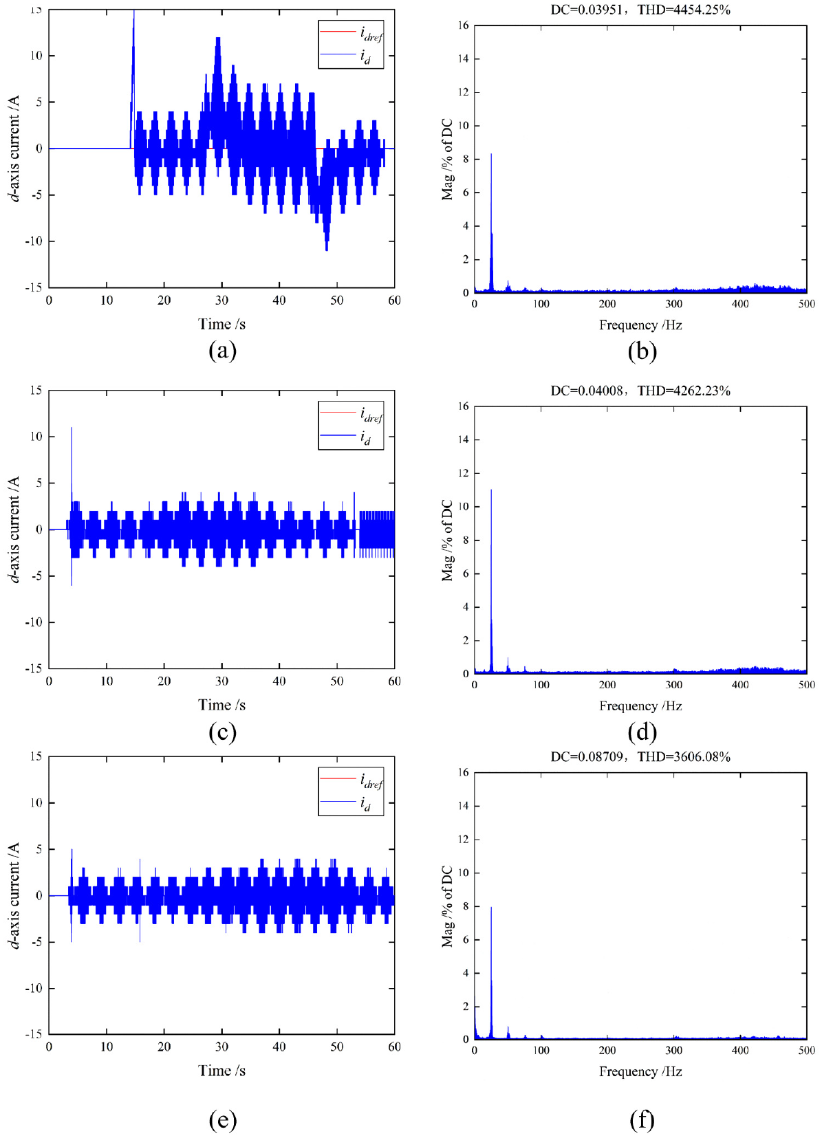
Figure 13 shows the comparison results of d-axis currents tracking of the three methods under the condition of load torque variation. It can be known from the results in Figure 13 that the d-axis current of the traditional PID method shows certain distortion, while THD of the method proposed in this paper is relatively small, reducing by 26.02% compared with the SDF-ADRC method and by 32.80% compared with the traditional PID method.

Under load torque variation conditions, comparison of the d-axis current tracking effects of three methods: (a) the d-axis current tracking of PID method, (b) the d-axis current THD of PID method, (c) the d-axis current tracking of SDF-ADRC method, (d) the d-axis current THD of SDF-ADRC method, (e) the d-axis current tracking of SDF-ADRC with two filters method, and (f) the d-axis current THD of SDF-ADRC with two filters method.
Figure 14 shows the comparison results of the q-axis currents tracking of the three methods under the condition of load torque variation. It can be known from the results in Figure 14 that THD of the method proposed in this paper is relatively small. Compared with the SDF-ADRC method, it is reduced by 11.42%, and compared with the traditional PID method, it is reduced by 17.88%. Under the condition of load torque variation, compared with the other two methods, the current ripple and THD of the method proposed in this paper are smaller, and the current dynamic response is faster.

Under load torque variation conditions, comparison of the d-axis current tracking effects of three methods: (a) the q-axis current tracking of PID method, (b) the q-axis current THD of PID method, (c) the q-axis current tracking of SDF-ADRC method, (d) the q-axis current THD of SDF-ADRC method, (e) the q-axis current tracking of SDF-ADRC with two filters method, and (f) the q-axis current THD of SDF-ADRC with two filters method.
Under the condition of inductance parameter variation
Figure 15 shows the comparison results of the speed tracking of the three methods under the condition of inductance parameter variation. It can be known from the results in Figure 15 that the traditional PID method has the largest overloading and offset, followed by the SDF-ADRC method. The method proposed in this paper has smaller speed pulsation, smaller overloading and offset, and can quickly track the speed changes and restore to a stable state.

Under inductance parameter variation conditions, comparison of the speed tracking effects of three methods.
Figure 16 shows the comparison results of d-axis currents tracking of the three methods under the condition of inductance parameter variation. It can be known from the results in Figure 16 that the d-axis current of the traditional PID method shows certain distortion, while THD of the method proposed in this paper is relatively small, reducing by 30.49% compared with the SDF-ADRC method and by 31.55% compared with the traditional PID method.

Under inductance parameter variation conditions, comparison of the d-axis current tracking effects of three methods, (a) the d-axis current tracking of PID method, (b) the d-axis current THD of PID method, (c) the d-axis current tracking of SDF-ADRC method, (d) the d-axis current THD of SDF-ADRC method, (e) the d-axis current tracking of SDF-ADRC with two filters method, and (f) the d-axis current THD of SDF-ADRC with two filters method.
Figure 17 shows the comparison results of the q-axis currents of the three methods under the condition of inductance parameter variation. It can be known from the results in Figure 17 that THD of the method proposed in this paper is relatively small. Compared with the SDF-ADRC method, it is reduced by 18.13%, and compared with the traditional PID method, it is reduced by 25.40%.

Under inductance parameter variation conditions, comparison of the d-axis current tracking effects of three methods: (a) the q-axis current tracking of PID method, (b) the q-axis current THD of PID method, (c) the q-axis current tracking of SDF-ADRC method, (d) the q-axis current THD of SDF-ADRC method, (e) the q-axis current tracking of SDF-ADRC with two filters method, and (f) the q-axis current THD of SDF-ADRC with two filters method.
Under the condition of inductance parameter variation, compared with the other two methods, the current ripple and THD of the method proposed in this paper are smaller, and the current dynamic response is faster.
Under the condition of flux linkage parameter variation
Figure 18 shows the comparison results of the speed tracking of the three methods under the condition of flux linkage parameter variation. It can be known from the results in Figure 18 that the traditional PID method and the SDF-ADRC method show large overloading and offsetting, and have relatively slow dynamic response characteristics. However, the method proposed in this paper can quickly track the speed changes, restore to a stable state, has smaller overloading and offsetting, smaller speed pulsation, and has strong robustness and anti-interference performance.

Under flux linkage parameter variation conditions, comparison of the speed tracking effects of three methods.
Figure 19 shows the comparison results of d-axis currents tracking of the three methods under the condition of flux linkage parameter variation. It can be known from the results in Figure 19 that the d-axis current of the traditional PID method shows certain distortion, the current ripple of the SDF-ADRC method is relatively large, while THD of the method proposed in this paper is relatively small, reducing by 15.39% compared with the SDF-ADRC method and by 19.04% compared with the traditional PID method.
Under flux linkage parameter variation conditions, comparison of the d-axis current tracking effects of three methods: (a) the d-axis current tracking of PID method, (b) the d-axis current THD of PID method, (c) the d-axis current tracking of SDF-ADRC method, (d) the d-axis current THD of SDF-ADRC method, (e) the d-axis current tracking of SDF-ADRC with two filters method, and (f) the d-axis current THD of SDF-ADRC with two filters method.
Figure 20 shows the comparison results of the q-axis currents tracking of the three methods under the condition of flux linkage parameter variation. It can be known from the results in Figure 20 that THD of the method proposed in this paper is relatively small. Compared with the SDF-ADRC method, it is reduced by 38.44%, and compared with the traditional PID method, it is reduced by 50.41%. Under the condition of flux linkage parameter variation, compared with the other two methods, the current tracking effect of the method proposed in this paper is better, with smaller current ripple and THD, and a faster tracking dynamic response.

Under flux linkage parameter variation conditions, comparison of the d-axis current tracking effects of three methods: (a) the q-axis current tracking of PID method, (b) the q-axis current THD of PID method, (c) the q-axis current tracking of SDF-ADRC method, (d) the q-axis current THD of SDF-ADRC method, (e) the q-axis current tracking of SDF-ADRC with two filters method, and (f) the q-axis current THD of SDF-ADRC with two filters method.
Table 2 shows the static performance comparison of the three control methods under four working conditions. Table 3 shows the dynamic performance comparison of the three control methods under four working conditions. It can be known from Tables 2 and 3 that under the four working conditions, the absolute deviation of the speed of the traditional PID method is relatively large, the current ripple of the d, q axis is relatively large, and the tracking performance is poor. Compared with the traditional PID method, the SDF-ADRC method has reduced indicators values such as absolute deviation of rotational speed, absolute deviation of d, q axis currents, and THD, and has improved in terms of performance. The performance index of the method proposed in this paper is relatively small, the speed tracking effect is good, the overloading and offsetting are low, the current ripple is small, and it can quickly track the current changes. It has better robustness and anti-interference ability for parameter changes and disturbances.
The static preference comparison of the three methods under the four conditions.

The dynamic preference comparison of the three methods under the four conditions.

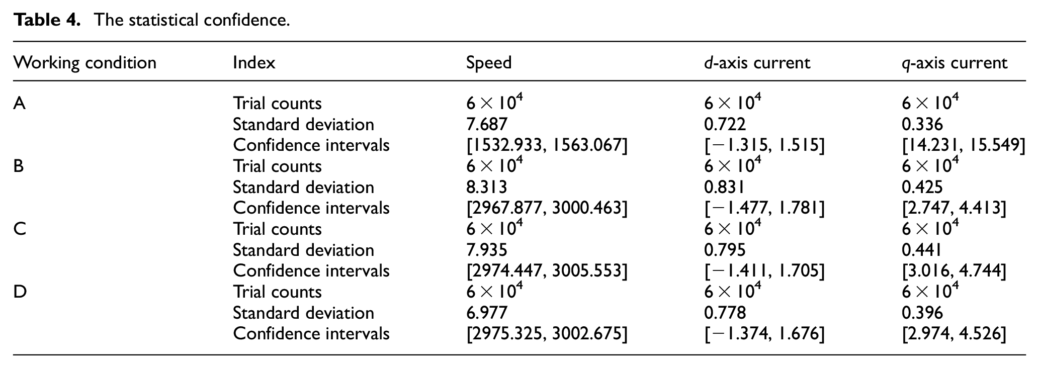
Table 4 presents the statistical confidence levels under the experimental conditions, providing the trial counts, standard deviation, and confidence intervals under four working conditions. It also offers the fluctuation ranges of the speed and d, q axis current, enhancing the accuracy of the experimental results and providing a basis for judging abnormal values.
The statistical confidence.
Conclusion
This paper analyzes the parameter sensitivity of current loop, extends the total disturbance of error dynamic equation into a new state, constructs a single-degree-of-freedom ADRC control model, designs ESO and control law, and evaluates its anti-interference performance through frequency domain analysis. On this basis, an adaptive notch filter and a first-order low-pass filter are designed to reduce the steady-state error between estimated and actual disturbances, thereby improving observation performance. The main conclusions are as follows:
Different parameters have different effects on d-q axis currents. Resistance mismatch has smaller impact on current, while inductance and flux linkage mismatches have greater effects.
The proposed single-degree-of-freedom ADRC model with dual filters requires less parameter tuning work and demonstrates stronger anti-interference performance in frequency domain analysis.
Experimental results show that the proposed method has higher tolerance for parameter variations and load disturbances, exhibits good robustness and anti-interference performance, effectively reduces speed and current fluctuations, and suppresses buffeting.
Future work needs to further explore the collaborative optimization mechanism of dynamic filters. For example, an adaptive parameter tuning algorithm based on frequency-domain coupling analysis should be designed to solve the phase lag problem of slot filters, and real-time parameter identification technology should be integrated to directly compensate for the sensitivity of inductance and flux linkage mismatch. Meanwhile, the bottleneck of hardware implementation should be broken through, the composite control strategy should be expanded, the lightweight ESO model or FPGA parallel computing architecture should be developed to meet the real-time requirements of high-speed motor control, the nonlinear stability theory should be improved, the global stability criterion and the quantitative robustness evaluation system should be established, and the large-scale application of this method in scenarios such as new energy drive and precision servo should be promoted.
Footnotes
Appendix A
Table 5 shows the meaning of variable:
Handling Editor: Chenhui Liang
Funding
The author(s) disclosed receipt of the following financial support for the research, authorship, and/or publication of this article: This research was funded by the Key Construction Subject Scientific Research Project of Guangdong Province (No.2024ZDJS097).
Declaration of conflicting interests
The author(s) declared no potential conflicts of interest with respect to the research, authorship, and/or publication of this article.
Data availability statement
The data used to support the findings of this study are included within the paper.