
Abstract
Wind load is a critical factor that threatens the structural safety of rooftop PV systems. Experimental tests in a wind tunnel investigated the impact of wind direction and roof slopes ranging from 15° to 60° on the wind loads experienced by PV arrays installed on double-pitched roofs. The results indicate that the entire array experiences wind pressure on the windward side and weaker suction forces on the leeward side. Increasing the roof slope enhances the overall wind pressure on the windward side apparently but does not increase the overall suction on the leeward side. Considering the most unfavorable negative net wind pressures across all wind directions, it was found that increasing the roof slope does not significantly affect the most unfavorable negative mean net wind pressure, but it substantially lowers the most unfavorable negative peak net wind pressure and shifts their occurrence toward the ridge of the roof. The wind pressure recommended in ASCE/SEI 7-22 is conservatively biased, the experimental results for roof slopes larger than 30° show a deviation of 60%–70% from the recommended values in the code.
Introduction
Amid global efforts toward carbon peaking and neutrality, photovoltaic (PV) power has rapidly expanded due to its environmental and economic advantages. 1 Rooftop PV installations, widely adopted in urban areas, conserve land and improve building energy efficiency. 2 However, their exposure to complex wind environments raises significant structural safety concerns. 3 Extreme weather events, such as typhoons, can lead to panel displacement and structural damage, posing risks to both buildings and occupants. Installed near roof edges or on inclined surfaces, PV arrays experience highly variable wind loads influenced by wind direction, roof geometry, and slope. A clear understanding of these wind load characteristics is essential for enhancing structural reliability, optimizing mounting systems, and guiding layout design.
Rooftop PV systems are located within complex building-induced flow fields, resulting in more intricate wind load variations than those on ground-mounted systems. Most existing studies focus on flat-roof installations, examining the effects of panel slope, installation gaps, and parapets. Among these, slope is considered a key factor influencing wind loads. Some studies report that increasing slope leads to significantly higher average and peak loads.4,5 However, findings vary: Kopp 6 observed that pressure coefficients increase linearly with slope below 10°, but remain nearly constant beyond that. Other studies show that slope has limited influence under most wind directions, with notable effects only at critical angles. 7 Research also suggests that reducing row spacing, increasing edge distance, or adding parapets can mitigate wind loads by enhancing shielding or reducing aerodynamic interference.8–10 By contrast, installation gap and panel height above the roof have relatively minor effects. 11
Compared to flat-roof PV systems, studies on wind loads for sloped-roof installations remain limited. Based on roof type, such systems can be classified as mounted on either open-gable or enclosed-gable roofs. Li et al. 12 examined open-gable PV carports with 20° and 30° slopes, finding that extreme suction increased with slope and peaked near the roof ridge. PV panels on sloped roofs may be mounted either parallel to or tilted from the surface. Naeiji et al. 13 showed that tilted panels experience higher wind pressures than parallel ones, with peak coefficients rising with tilt angle, while roof clearance and building height had minimal influence. Wang et al. 14 investigated wind loads on PV panels mounted on a 35° dual-slope roof, comparing results with ASCE standards, though without analyzing slope effects. Aly and Bitsuamlak 15 found lower wind loads on PV panels installed parallel to a 22.6° roof compared to a 14° slope, with measured loads lower than ASCE predictions. Yao et al. 16 studied parallel PV panels on a 30° sloped roof and found that increasing clearance from 15 to 20 cm raised critical suction by 18.8%, while noting the conservativeness of current design standards. Stenabaugh et al. 17 showed that increased module spacing and reduced mounting height improve pressure equalization, thereby significantly reducing net wind loads.
Davenport
18
classified sloped-roof buildings into three categories: low (0°–15°), medium (15°–30°), and high slope (30°–45°). Most existing studies focus on PV systems installed on low and medium slope roofs, but steeper slopes often required by climatic or architectural considerations remain underexplored. In such cases, wind load patterns can become significantly more complex, necessitating further investigation. This study employs wind tunnel testing to examine the influence of roof slope and wind direction on the wind loads of PV arrays mounted parallel to sloped roofs. The results are also compared with the ASCE/SEI 7-22 standard,
19
with the aim of providing more accurate and practical reference data for engineering designers. Moreover, since the standard does not provide
Methodology
Test model
The experimental setup is shown in Figure 1. The actual dimensions of a single PV panel are 2.278 m × 1.134 m × 0.035 m, and the panels are installed parallel to the roof surface at a height of 0.12 m above the roof. The row spacing and column spacing between panels, denoted as

Schematic of the model.
Dimensions of models.

The wind tunnel test model was built at a geometric scale of 1:15, as shown in Figure 2. Due to the symmetry of the PV array along the roof ridge, only one side of the roof was selected as the test region. The model building frame is constructed with aluminum alloy profiles and the walls and roof are made of acrylic panels. The PV panels are made of smooth ABS material with embedded pressure-measuring copper tubes. Each panel was uniformly equipped with six pressure measurement points on both the upper and lower surfaces. In total, the array contained 432 pressure measurement points, with the detailed distribution shown in Figure 3. Due to pressure measurement point were installed only on one side of the roof surface, wind loads were tested within the range of 0°–180°, the wind direction was tested at intervals of 10°, for a total of 19 wind directions.

Experimental model.

Measurement point and definition of wind direction.
Wind profile
The experiment was conducted in the atmospheric boundary layer wind tunnel at Xiamen University of Technology. The dimensions of the low-speed test section were 3.6 m (height) × 6 m (width) × 25 m (length), with a wind speed range of 0–30 m/s. The test region demonstrated excellent flow field performance, with a velocity non-uniformity of less than 1.5%, and an average airflow deviation angle of less than 1.0°. The atmospheric boundary layer is measured using a system consisting of the Turbulent Flow Instrumentation Cobra Probe and dedicated software. The Cobra probe has been carefully calibrated and can be used to obtain average wind speed, turbulence intensity, velocity fluctuation data, and power spectra of pulsating wind in the wind tunnel flow field. In addition, wind speed profiles can be reconstructed by taking measurements at multiple vertical or horizontal positions. The reference height point was set at 10 m and the mean wind speed at the reference point was about 10.0 m/s using the Cobra probe. The wind tunnel is equipped with turbulence-generating elements (spires and roughness elements) that allow for the simulation of atmospheric boundary layer flows with a turbulence intensity of below 0.5%. The wind speed profile and the turbulence intensity profile in the atmospheric boundary layer are shown in Figure 4(a), which align well with the requirements of the surface roughness category B in the GB50009-2012. 20 The longitudinal turbulence energy spectrum, as shown in Figure 4(b), satisfies the requirements of the Von Karman spectrum. The turbulence integral scale was 1.79 m. The test uses the DTC Initium electronic pressure scanning valve and data processing software to measure the wind pressure. The pressure measurement signals were sampled at a frequency of 330 Hz for a duration of 160 s, resulting in a total of 52,800 data points. To reduce the influence of outliers on the results, the data points from the first and last 1.5 s of the sampling period were excluded from the analysis.

(a) Profile of mean wind speed and turbulence intensity and (b) spectrum of streamwise turbulence.
Pressure coefficients
The dimensionless wind pressure coefficients
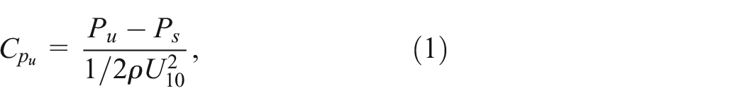

where

In this paper, the signs of the wind pressure coefficients at the measuring points are defined as follows: for single-sided measuring points, the pressure is positive when it points to the PV panel and negative when it leaves the PV panel; for double-sided measuring points, the pressure is positive when it points to the building and negative when it leaves the building. To analyze the loading on individual PV panels or arrays, the area-weighted average wind pressure coefficient

where

where the peak factor
Test results and analysis
Effect of wind direction on wind pressure distribution of PV modules
Figures 5 and 6 show the mean and RMS wind pressure coefficients distributions on the upper and lower surfaces of the PV array in model B at two specific wind directions, 0° and 90°, respectively. The results indicate that both the mean and RMS wind pressure coefficients exhibit either left-right symmetry or symmetry about the roof ridge at these two wind directions, verifying the accuracy of the experimental measurements. From Figure 5(a), it can be observed that at a wind direction of 0°, the mean wind pressure on the upper surface of the PV panel gradually decreases with increasing distance from the windward eave. In the upstream region near the roof ridge, the mean wind pressure changes more dramatically, likely due to the accelerated airflow caused by flow separation around the ridge. Downstream of the ridge, the pressure remains nearly constant, as this region lies within a separation zone. The mean wind pressure distribution on the lower surface of the PV panel (Figure 5(b)) is similar to that on the upper surface. However, on the windward side, the upper surface wind pressure is significantly greater than that on the lower surface, while on the leeward side, the upper surface wind pressure is generally slightly lower. Furthermore, although the RMS wind pressure on the lower surface is small, the distribution patterns of RMS wind pressure on both surfaces (Figure 5(c) and (d)) are consistent: a pronounced high-fluctuation region forms near the windward eave due to separation effects, while other areas experience relatively low fluctuating wind loads.

Wind pressure coefficients on the upper and lower surfaces of model B (

Wind pressure coefficient on the upper and lower surfaces of model B (
When wind direction is 90°, the mean wind pressure on the upper surface of the PV panel (Figure 6(a)) decreases progressively along the flow direction, while the RMS wind pressure (Figure 6(c)) also diminishes accordingly. This phenomenon is likely due to strong airflow separation occurring at the right-side eave. As the distance from the separation zone increases, the pressure gradually recovers and the RMS wind pressure correspondingly decreases. At this wind direction, the mean wind pressure on the lower surface of the PV panel (Figure 6(b)) and its RMS wind pressure (Figure 6(d)) also exhibit distribution patterns similar to those on the upper surface. However, the mean wind pressure on the lower surface is slightly higher than that on the upper surface, while the RMS wind pressure is slightly lower, which may be attributed to the confined space beneath the lower surface.
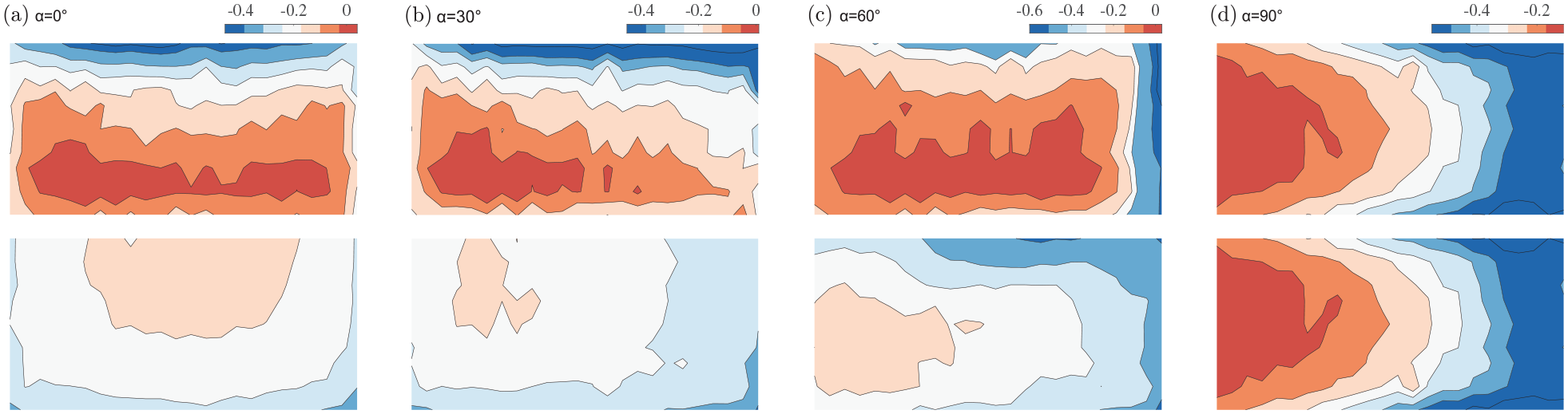
PV panels are dual-loaded structures, and the net wind pressure is more valuable for structural design than the unilateral wind pressure. Figure 7 shows the mean net wind pressure for model B at wind directions of 0°, 30°, 60°, and 90°. It should be noted that area-weighted averaging was applied to each PV panel to avoid fluctuations of individual measurement points and ensure the clarity of the contour maps. It can be observed that at the wind direction of 0°, the net wind pressure on the windward side is positive, with the maximum positive pressure occurring near the side eave, likely caused by airflow impingement induced by the corner vortices. On the leeward side, the pressure is slightly negative. When the wind direction increases to 30°, the windward side is still under positive pressure, with peaks decreasing slightly and the location where it appears shifting to the downstream eaves, while the pressure coefficient on the leeward side approaches zero. At the wind direction of 60°, negative pressure begins to appear near the windward eave, but the downstream region remains under positive pressure, and the pressure on the opposite side is relatively small. At a wind direction of 90°, the wind suction at the windward eave reaches its maximum, and along the flow direction, the net wind pressure gradually transitions from negative to positive in a monotonic manner.

Mean net wind pressure coefficient of model B (
The separation of vortices around the building induces pressure fluctuations. In addition to the mean values, the negative peak net wind pressure is also critical indicators for structural design. Figure 8 illustrates the distribution of the negative peak net wind pressure for model B at wind directions of 0°, 30°, 60°, and 90°. At a wind direction of 0°, although the mean net wind pressure on the windward eave is positive, the high fluctuations caused by the separation phenomenon result in a peak suction at this location. Similarly, in the leeward region, the fluctuating wind loads also produce peak suction. At a wind direction of 30°, the distribution characteristics of the negative peak net wind pressure are similar to those at 0°, but the location of extreme suction shifts due to changes in the wind direction. When the angle of direction of the wind increases to 60°, the negative peak net wind pressure coefficient below −0.5 appears near the right eaves, and the wind suction area extends to the entire lower half of the eaves. When the wind direction changes to 90°, the wind suction on the roof is significantly stronger, and the negative peak net wind pressure gradually increases along the flow direction.
Negative peak net wind pressure coefficient for model B (
To quantitatively investigate the variation of rooftop PV wind loads, the overall wind pressure coefficient of the array with wind direction is shown in Figure 9. It can be observed that the wind pressure coefficients on both the upper and lower surfaces of the PV modules exhibit a consistent trend as the wind direction changes: within the range of 0°–90°, the mean and negative peak wind pressure coefficients on both surfaces first increase, then gradually decrease and finally increase again, with the minimum value occurring around 120°. Notably, the RMS wind pressure on both surfaces shows little variation across different wind directions. Additionally, Figure 9(b) presents the variation in net wind pressure with wind direction. The mean and negative peak net wind pressure decreases as the wind direction increases, transitioning to wind suction near a wind direction of 80° and reaching the minimum value at a wind direction of 140°, after which they gradually increase. Meanwhile, the RMS net wind pressure monotonically decreases with increasing wind direction. Overall, the net wind pressure coefficient calculated for the entire roof is approximately 0.1, which is apparently lower than the single-sided counterpart.

Variation of the overall wind pressure of model B (
Effect of roof angle on wind pressure distribution of PV modules
Figure 10 illustrates the overall average wind pressure coefficients on the upper and lower surfaces of the PV array under different roof slopes. From the figure, it can be observed that within the wind direction range of 0°–90° (windward condition), the mean wind pressure coefficients on both the upper and lower surfaces exhibit a monotonic increase with the rise in roof slope. In the leeward condition (wind directions greater than 90°), the wind pressure coefficients gradually decrease as the roof slope increases. Furthermore, the greater the roof slope, the smaller the wind direction at which the peak suction occurs.
Variation of the overall wind pressure coefficients of different models with wind direction: (a) upper surface mean wind pressure and (b) lower surface mean wind pressure.
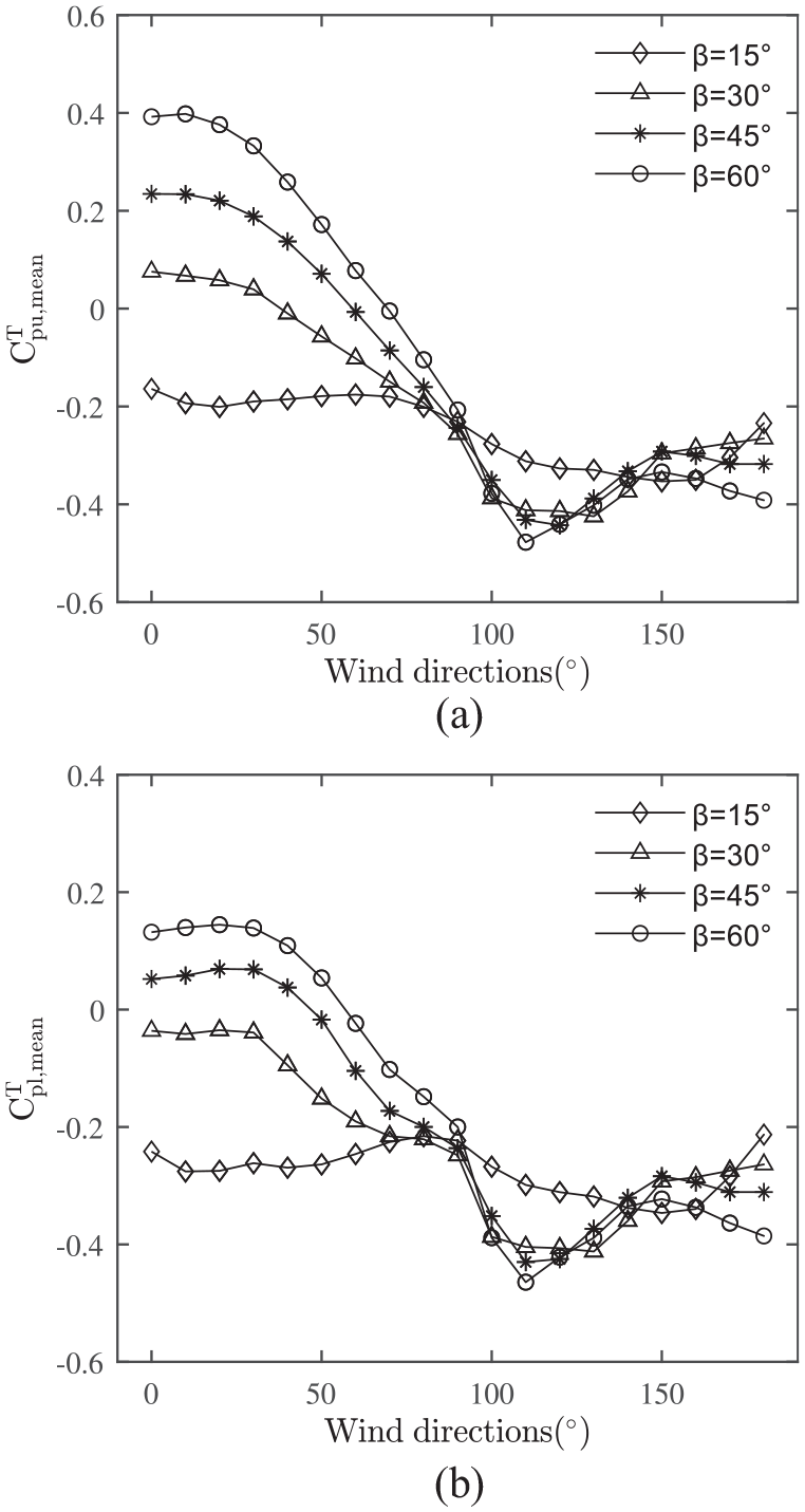
Figure 11 illustrates the variation of the overall mean and the most critical negative peak net wind pressures on the PV array under different roof slopes. As shown in Figure 11(a), within the windward range of 0°–90°, the mean net wind pressure on the PV panels increases as the roof slope increases. This is because a larger roof slope leads to more pronounced airflow impingement on the windward side. In the leeward range of 90°–180°, the mean net wind pressure coefficient is nearly zero and is unaffected by the roof slope, due to the small pressure gradient in the leeward region, where the pressures on the upper and lower surfaces of the PV panels tend to balance out. By definition, the negative peak net wind pressure is lower than the mean value, resulting in wind suction on the leeward side of the PV panels. As shown in Figure 11(b), the overall net suction of the PV array remains consistently low across different roof slopes, with no significant correlation to the wind direction.

Variation of the overall net wind pressure coefficients of different models with wind direction: (a) mean net pressure coefficients and (b) the most critical negative peak net pressure coefficients.
PV panels are similar to cladding structures, and their structural design must account for the most unfavorable wind pressures from all wind directions. The mean and negative peak of the most unfavorable net wind pressure are shown in Figures 12 and 13, respectively. The most unfavorable negative net wind pressure is defined as the minimum net wind pressure coefficient (peak suction) observed in all directions of the wind. From these figures, it can be observed that the most unfavorable mean net wind pressure for different models follows an X-shaped distribution, with suction peaks occurring near the side eaves. As the roof slope increases, the suction peak near the side eaves remains relatively unchanged, while the most unfavorable mean net wind pressure near the roof ridge increases. This is likely due to the separation vortices near the ridge shifting farther from the roof surface, resulting in weaker suction. The distribution patterns of negative peak and mean suction values are similar, both characterized by higher suction near the side eaves and lower suction in the center of the roof. Notably, as the roof slope increases, the peak value of the negative peak net wind pressure decreases significantly, maximum difference is 30%, and its location gradually shifts toward the roof ridge. This suggests that the roof slope has a significant effect on the distribution and positioning of extreme suction values. It is consistent with the trend obtained from the study by Chen et al. 21
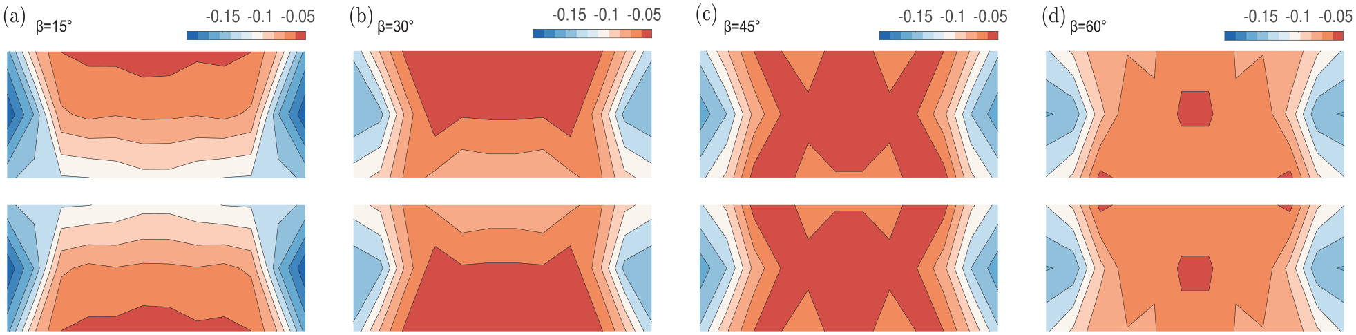
The most unfavorable mean net wind pressure coefficient of different models for all wind directions: (a)
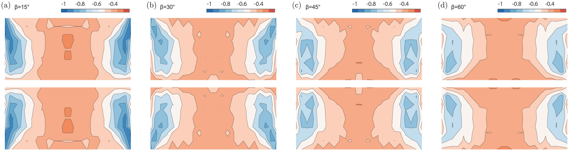
The most unfavorable negative peak net wind pressure coefficient of different models for all wind directions: (a)
Comparison with normative results
Currently, there are several standards that provide guidelines for calculating wind loads on photovoltaic panels, such as AS/NZS 1170.2-2011 and JIS C 8955-2017. However, ASCE/SEI 7-22 is the most recent version and offers more details for calculating wind loads on sloped roof photovoltaic systems. Therefore, it was deemed the most appropriate standard for comparison in this study. In ASCE/SEI7-22 Figure 30.3-2D, the roof is divided into three zones, as shown in Figure 14, with slightly different standard curves for each zone. Given that Zones 2 and 3 in the model used in this study do not fully encompass entire PV panels, all PV panels are considered to be within Zone 1 for simplicity. The combination methods, number of combinations, and corresponding areas of the PV arrays are listed in Table 2.
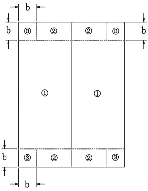
ASCE/SEI7-22 roof area division (27° <
Combination of PV modules with different tributary areas.

The method proposed by Kopp
6
was used to calculate the most unfavorable negative peak net wind pressure of neighboring PV modules for all wind directions. In Figure 15(a), there are 468 blue data points, each representing the most unfavorable negative peak wind pressure for a specific array combination. Among these, the red data points denote the minimum values for arrays with the same area. By performing a least-squares fit on these data points, a reduction curve of the peak net pressure coefficients with respect to the effective windward area can be obtained. Furthermore, to quantify the comparison between the experimental and standard results, the methods suggested by Wang et al.
22
and Pierre et al.
23
were employed to convert the experimentally obtained peak net pressure coefficients CP,min into an equivalent external wind pressure coefficient

where

R
1 represents the conversion factor for wind speed duration and is taken as 0.49 based on the curve in the study of Drust.
24
R2 represents the terrain category conversion factor, with a value of 1. R3 is the reference height conversion factor, also set to 1. Kz denotes the Velocity Pressure Exposure Coefficient, with a value of 1. Kzt represents the Topographic Factor, which is set to 1 in this study. The Wind Directionality Factor, Kd, is assigned a value of 0.85. Ke is the Ground Elevation Factor, taken as 1 in this study.

(a) Variation of the most unfavorable negative peak area-averaged net wind pressure coefficients (MUNPANWPC) with effective wind area for solar arrays; red filled: the minimum values for arrays with the same area and (b) comparison of Zone 1 test results with ASCE/SEI7-22.
Figure 15(b) shows the reduction curve of the unfavorable negative peak of the equivalent wind pressure coefficient of the PV module with the effective wind area. It can be seen that the increase in the roof inclination angle leads to a decrease in the extreme wind suction, which is consistent with previous experimental results. The experimental results for all roof slope models are lower than the recommended values in ASCE/SEI7-22. Specifically, the experimental results for model A are in good agreement with the code values when the tributary area is greater than 27.9 m2. However, as the tributary area decreases, the discrepancy between the experimental results and the code values gradually increases. For models B, C, and D, the experimental results show a 60%–70% difference from the recommended values. The observed discrepancies may be attributed to simplifications in the code provisions, and the influence of specific installation parameters, such as the mounting height of the photovoltaic panels and the spacing between arrays, all of which can significantly affect wind load distributions. Based on this experimental study, the recommended values provided in ASCE/SEI 7-22 are reasonably appropriate for the wind resistance design of PV panels on roofs with larger tributary areas, as they allow for a certain conservative margin. However, when the tributary area is smaller, the recommended values in the standard appear to be overly conservative. Similar conclusions were reached in the study of Aly and Bitsuamlak. 15
Conclusions
This study examines the wind load characteristics of PV arrays installed parallel to sloped roofs with angles ranging from 15° to 60° using wind tunnel experiments. The main conclusions are as follows:
The net wind pressure on PV panels is significantly lower than the unilateral pressure, with critical suction zones typically occurring near the roof eaves and ridges. As wind direction increases from 0° to 180°, the net wind pressure shifts from positive to suction, highlighting the importance of directional loading in design.
Roof slope has a pronounced impact on wind pressure under windward conditions, with both mean and peak net pressures increasing as slope increases. In contrast, leeward conditions produce relatively low suction that is less sensitive to roof slope. Considering results across all wind directions, the distribution of the most unfavorable mean and negative peak net pressure coefficients indicates that the peak values of mean suction and peak suction occur near the side eaves. An increase in roof slope slightly reduces the peak value of mean suction and significantly reduces the peak value of extreme suction, while also shifting its location toward the roof ridge.
The experimental results for model A (15°) are in close agreement with the recommended values in the code when the attached surface area exceeds 27.9 m2. However, for models B (30°), C (45°), and D (60°), the discrepancy between the experimental results and the recommended values ranges from 60% to 70%. Based on this experimental study, the wind load values for PV arrays in Zone 1 specified by ASCE/SEI7-22 are relatively conservative.
These results offer consultation to inform the structural design of rooftop PV systems, particularly for installations on steep roofs. This study is limited by the use of a single array configuration without considering other installation parameters. Future research should explore more diverse PV layouts and conduct detailed flow field analyses to better replicate real-world conditions.
Footnotes
Handling Editor: Divyam Semwal
Funding
The author(s) disclosed receipt of the following financial support for the research, authorship, and/or publication of this article: This work was supported by the Natural Science Foundation of Xiamen, China (Grant No. 3502Z20227068, No. 3502Z202371025) and the Scientific Research Projects of Xiamen University of Technology (Grant No. YKJ22026R).
Declaration of conflicting interests
The author(s) declared no potential conflicts of interest with respect to the research, authorship, and/or publication of this article.