
Abstract
Permanent magnet synchronous linear motor (PMSLM) has the advantages of simple mechanical structure and high thrust density. However, the simultaneous existence of end effect and cogging force aggravates the thrust ripple and affects the output characteristics of PMSLM. This paper proposes various rectangle and easily machinable auxiliary slots for core teeth to reduce thrust ripple. Firstly, the length, width and position of the auxiliary slot are parameterized by the finite element method, and the minimum detent force is solved to obtain the optimal slot size. Then, taking the air-gap flux density harmonic, average thrust and thrust ripple as reference indexes, the performance differences of the three auxiliary slots are compared. The results show that the auxiliary slot on the side of the tooth can reduce the thrust ripple by up to 22.4%, and the average thrust is only reduced by 3.7%. Finally, the correctness of the numerical simulation is verified by experiments.
Introduction
Permanent magnet synchronous linear motor (PMSLM) has the advantages of high thrust density, fast response and simple structure,1–3 it is widely used in high-precision fields such as precision CNC machine tools, laser machinery and semiconductor manufacturing equipment. However, due to the simultaneous existence of stator cogging force and side force, thrust ripple inherently degrades operational stability and compromises precision in applications such as CNC machining. 4 Therefore, the study of PMSLM thrust ripple has important theoretical and practical significance.
Many papers have investigated thrust ripple reduction. According to the structure of PMSLM, it can be optimized from three aspects: winding, permanent magnet and iron core. In Reference 5, a V-coil permanent magnet synchronous linear motor is designed to suppress the fluctuation of thrust without decreasing the average thrust. 5 In Reference 6, the primary structure obtained two asymmetric primary cores and two asymmetric windings to reduce the variation of the flux density by the core slotting. 6 There are also some researches on the optimization of permanent magnet structure, in Reference 7, a segmental permanent magnet linear synchronous motor with noninteger pole number (19.2-pole), 7 which has low detent force and high thrust, is presented. In Reference 8, reduce the detent force and increase the average thrust by adjusting the shape and pitch permanent magnet. 8 Primary core structure optimization includes many aspects: the icon core is segmented to reduce the end force, and increase the width of the side tooth or design reverse slots to offset end force, and finally reduce thrust ripple.9–11
Electromagnetic optimization structure combined with corresponding multi-objective algorithms can also improve motor output performance. In References 12 to 13, the performance of the motor is optimized by adopting a surrogate model and a multi-objective optimization algorithm.12–13 In Reference 14, the multi-objective optimization based on sequential subspace optimization was proposed. 14 In Reference 15, a new Adaptive Pareto Algorithm allows to reduce the computational cost and to achieve an even distribution of the optimal solutions in the Pareto optimal front. 15
Although the above structural optimization methods improve the thrust output performance of PMSLM, they also complicate the motor structure and increase the difficulty of machining and assembly. The auxiliary slot has the characteristics of simple structure and easy processing, and can also improve the motor performance. At present, it also has many applications in rotating electrical machines. In Reference 16, compare the influence of three auxiliary slots on radial electromagnetic force and the suppression of unbalanced electromagnetic force. 16 In References 17 and 18, the influence of different auxiliary slot sizes on motor performance is calculated.17–18 However, the application of auxiliary slot in linear motor has not been mentioned in the paper, and the influence of its size, location and number on the air gap flux density harmonics, detent force and thrust ripple also needs further research.
This paper takes minimizing thrust ripple as the optimization objective, and compares different schemes of auxiliary slot motors to obtain the optimal auxiliary slot size structure.
Structure and parameters of the PMSLM
Figure 1 shows the motor’s structure, which comprises the air gap, the secondary component and the primary component. The primary consists of a iron and a plurality of rectangular windings as mover, the permanent magnets are surface mounted on the secondary back iron as stator. The major constituent parameters of the motor are listed in Table 1. The slot to pole ratio of PMSLM motor is 3:4, which can be seen that an expansion of the 3-slot/4-pole motor by increasing the number of slots and permanent magnets.

Structure of PMSLM.
Parameters of the PMSLM.

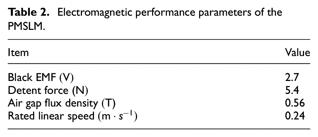
Then the electromagnetic performance parameter of PMSLM are obtained through finite element analysis, as shown in Table 2.
Electromagnetic performance parameters of the PMSLM.
Thrust model of linear motor
Solution of air gap flux density
The air gap of the motor has an important influence on the magnetomotive force (MMF) of the magnetic circuit. When the air gap changes slightly, the stability of the motor’s operation performance will be greatly affected. In the motor, the stator surface or rotor surface has a slot design, and the magnetic flux density at the slot is always reduced. When considering the influence of slotting in the average permeability of air gap, a longer equivalent air gap can be used
When the stator and rotor surfaces have slots, the complete Carter coefficient

Then the equivalent air gap

Although the calculation results obtained by applying the above equations are not accurate, they can usually meet the practical application. The most accurate result can be obtained by using the finite element method and setting dense element grids at the air gap, so as to get the magnetic force line distribution diagram of the air gap field, as shown in Figure 2.

Air gap flux lines.
In the rotating motor, the auxiliary slots are mainly distributed on the stator teeth and rotor surface, and their size and number can change the magnetic circuit. Therefore, the mutation of air gap can be suppressed by selecting the optimal size length and appropriate number, so as to improve the stability of motor operation. The distribution of the flux lines of the auxiliary slots are shown in Figure 3.

Air gap flux lines of auxiliary slots: (a) side slots and (b) bottom slots.
Effect of auxiliary slots on linear motor
In addition to the cogging force, there is also the end force generated by the disconnection of the primary iron in the linear motor. Both will affect the change of air gap magnetic flux density at the same time. As a result, the output thrust ripples greatly. The side-end magnetic field lines are shown in Figure 4. Both The side and bottom auxiliary slots will affect the trend of the magnetic field lines, so that the end effect can be weakened or strengthened.

End distribution of magnetic force line: (a) traditional, (b) side slots, and (c) bottom slots.
Establishment of thrust model
If the time harmonic of the current is not considered, set the initial angle of phase a as 0, then the three-phase currents of the windings can be expressed as follows:

Then the thrust of PMSLM at any time is:
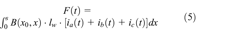
Where

Where
Therefore, when the amplitude of input current
The thrust ripple coefficient of linear motor is as follows:
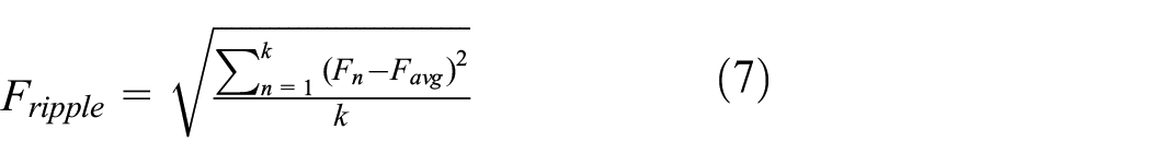
Where
The transient element model of PMSLM is shown in the Figure 5, using balloon boundary conditions. Iron core material is steel_1010, and permanent magnet material is NdFe30.

Transient element model of PMSLM.
Parametric analysis of auxiliary slots
For PMSLM, the main object of magnetic circuit design is the primary core, so this paper will study the influence of side and bottom slots of the primary core teeth on the thrust ripple, as well as the optimal auxiliary slots scheme.
Auxiliary slots at the both sides of the tooth
According to the symmetry of the primary core teeth of PMSLM. Firstly, the influence of the side auxiliary slots (Auxiliary-slot1) on the air gap flux density is studied. As shown in Figure 6: the depth, width and height of the slot are
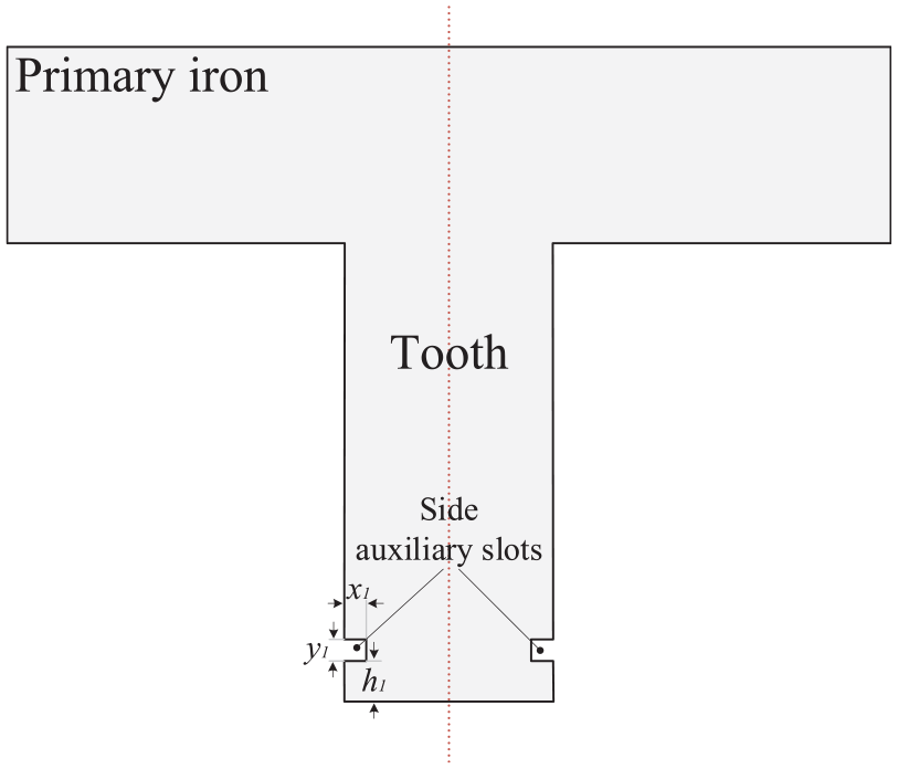
Auxiliary-slot1.
Auxiliary-slot1 design parameters.

In order to improve the operation performance of PMSLM and reduce the thrust ripple. The thrust ripple can be suppressed by reducing the detent force, which is the sum of the cogging force and the end force generated by PMSLM under the excitation free input. The cogging force is generated by the interaction between the slotted primary iron core and the secondary permanent magnetic field. Therefore, the minimum detent force is taken as the parameter optimization goal of Auxiliary-slot1.
Figure 7 shows the influence of the side auxiliary slot on the detent force. The coordinate points represent the sizes of all auxiliary slots. The larger the point, the redder the color means the greater the detent force, while the smaller the point, the bluer the color means the smaller the detent force. Since the period length of the detent force is constant, the result calculated in this paper is the absolute amplitude in a period. When
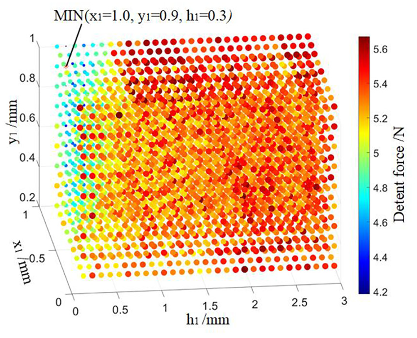
Effect of Auxiliary-slot1 on detent force.
Figure 8 shows the harmonic distribution of the air gap flux density of the Auxiliary-slot1. With the traditional PMSLM, the first-, second-, fourth-, fifth-, and sixth-order harmonics are reduced by approximately
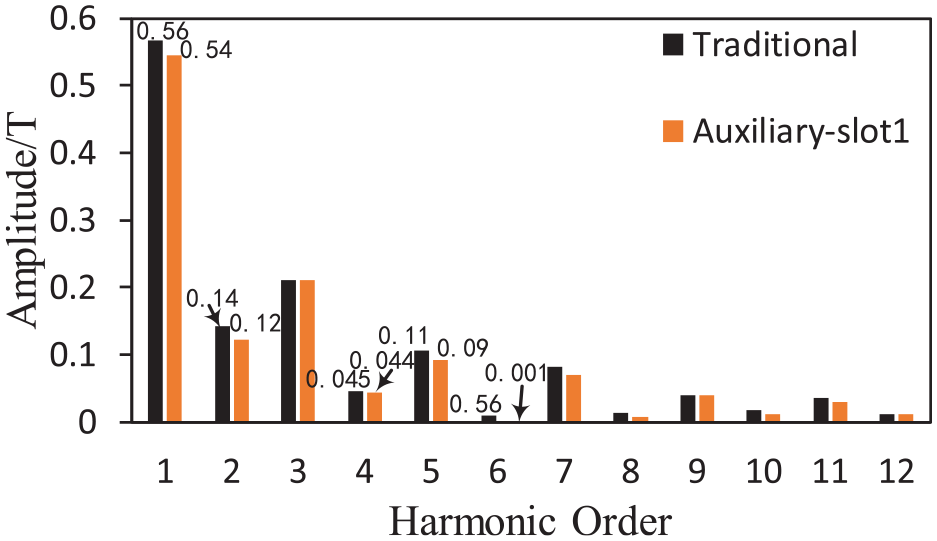
Air gap flux density harmonic spectrums of two motors.
Auxiliary slots at the bottom of the tooth
In addition to slotting at both sides of the teeth, the auxiliary slot can also be made at the bottom. At this time, the auxiliary slot is located on the outer surface of the tooth, which has a more direct impact on the air gap. The tooth width in this paper is
As shown in Figure 9: the depth and width of the slot are

Auxiliary-slot2.
Auxiliary-slot2 design parameters.

Figure 10 shows the influence of the two bottom auxiliary slots on the detent force. The expression of the detent force value is the same as that in Figure 7. The bottom auxiliary slot directly affects the equivalent air gap length, so the variation range of detent force is larger, the maximum value is

Effect of Auxiliary-slot2 on detent force.

Air gap flux density harmonic spectrums of two motors.
The results of parameterized solution of detent force for three bottom auxiliary slots (Auxiliary-slot3) are shown in Figure 12, where

Effect of auxiliary-slot3 on detent force.

Air gap flux density harmonic spectrums of two motors.
Performance analysis of PMSLM with different auxiliary slots
In the previous section, the optimal size and number of auxiliary slots under different models are obtained by comparing the detent force. This section will compare the electromagnetic performance of each PMSLM model to obtain the optimal scheme.
No-load back EMF
Firstly, the no-load back EMF of PMSLM without excitation is studied. The linear motor adopts three-phase concentrated winding, and the number of strands is 1, The winding layout diagram is shown in Figure 14. The no-load back EMF of the model can be obtained by solving under the rated linear speed
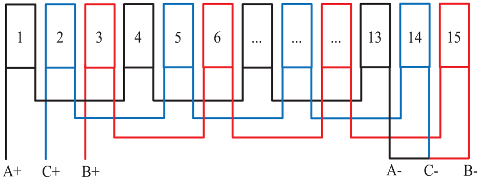
Winding layout.

Comparison of the back EMF.
The no-load back EMF of Auxiliary-slot1 and Auxiliary-slot3 has good positive linearity, and the amplitude of high-order harmonic also decreases. As shown in Figure 15 and 16.

Harmonics spectrums of the back EMF.
Average thrust and thrust ripple
When there is an excitation input, the three-phase windings of the motor are respectively connected with sinusoidal currents with

The average thrust values of PMSLM with different auxiliary slot structures are obtained through finite element simulation. As shown in Figure 17, the average thrust values of the three auxiliary slots are reduced. The maximum drop range of Auxiliary-slot3 is

Comparison of average thrust.
Then compare the thrust fluctuation of PMSLM. The number of values solved in this paper is 101, and the thrust fluctuation curve is obtained as shown in Figure 18 (excitation current

Comparison of thrust ripple.
Thrust characteristic comparison.
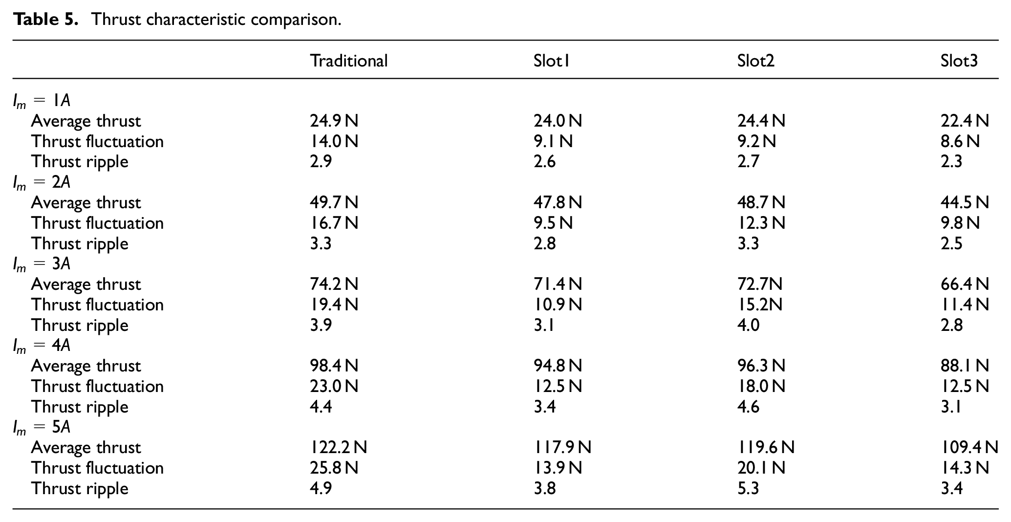
The thrust ripple of PMSLM will increase with the increase of excitation current, which also indicates that the greater the thrust, the greater the fluctuation. Among the three auxiliary slot structures, Auxiliary-slot1 and Auxiliary-slot2 have little influence on the average thrust. However, Auxiliary-slot3 reduced the thrust ripple by
Testing and results
In order to verify the correctness of theoretical analysis and finite element simulation, various primary core with auxiliary slots was manufactured and an experimental testing platform was built, as shown in Figures 19 and 20. The platform fixes the tension sensor on the secondary back iron and connects it to the load through a pulley. The drive control uses FOC method to drive the PMSLM and collects data through a collector.

Various primary core with auxiliary slots: (a) 15-slots cores and (b) enlarged view of auxiliary slots.

Testing platform.
The no-load back EMF waveforms of the whole motor with different auxiliary slots are shown in Figures 21 and 22, with the prototype of speed 0.24

Testing back EMF waveforms: (a) traditional. (b) auxiliary-slot1, and (c) auxiliary-slot2.

Harmonics spectrums of the back EMF comparison between experiment and simulation.
Conclusion
This paper designs and optimize the auxiliary slots for PMSLM to reduce thrust ripple and improve output performance. The effectiveness of this structure is demonstrated through the finite element analysis and experimental verification. The research conclusion is as follows:
The auxiliary slot on the side of the tooth can reduce the thrust ripple, and has little impact on the average thrust.
Multiple auxiliary slots on the bottom of the tooth will significantly reduce the average thrust and affect output performance of PMSLM.
Footnotes
Handling Editor: Xiaodong Sun
Funding
The author(s) disclosed receipt of the following financial support for the research, authorship, and/or publication of this article: The project was supported by the National Key R&D Program of China, with grant number 2024YFB3410001.
Declaration of conflicting interests
The author(s) declared no potential conflicts of interest with respect to the research, authorship, and/or publication of this article.