
Abstract
The mathematic model and computer analysis model of curve-surface conjugated face gear pair are developed on the basis of the principle of differential geometry. The meshing performance of face gear pair is discussed in detail, including point contact meshing characteristics, contact trajectory distribution, and sliding coefficient of the tooth surface. The tooth surface contact analysis model of curve-surface conjugated face gear pair is established, and the influences of installation errors on contact trajectory and transmission error are analyzed. The results showed that the face gear and the pinion with normal arc tooth profile mesh at the selected contact trajectory, and the point contact feature can be obtained when the tooth number of the pinion is equal to the shaper. Through the active design of contact trajectory, the curve-surface conjugated face gear pair can realize approximate pure rolling meshing, and the sliding coefficient of tooth surface is very small. Moreover, the curve-surface conjugated face gear pair has the characteristics of long pre-control contact trajectory and insensitive transmission error to installation error.
Keywords
Introduction
Face gear transmission is a new type of gear transmission, which has the advantages of large transmission ratio, pinion free from axial force, simple supporting structure, convenient installation and debugging, etc. It can effectively reduce the weight while increase the power-weight ratio of the transmission system, and is an ideal choice to replace the bevel gears in the transmission system.1–3
Litvin et al. 4 had made a comprehensive study on the meshing principle of face gear based on the conjugate theory of surface, and explained the forming principle of face gear. According to his theory, if the pinion with the same number of teeth as the shaper is used to mesh with the face gear, the meshing process of the face gear pair will hold the line contact feature. However, in the actual motion process, the partial load of the tooth surface will be caused by the existence of machining error, installation error, and other factors, which is very disadvantageous to the face gear transmission. To improve the transmission performance of face gear, Litvin et al.5,6 puts forward a method of machining face gear with a shaper with one to three teeth more than the pinion used for actual meshing. When the face gear obtained by this method engages with the pinion, the bearing contact can be obtained. The contact trajectory is a curve in the direction of the tooth height, and its length is less than the tooth height.
To further improve the meshing performance of face gear, many scholars put forward the technical scheme of modifying the paired pinion and face gear. Litvin et al. 7 used a shaper with parabolic tooth profile to process the face gear, which optimized the contact trajectory position of the face gear transmission, and effectively improved the stress condition of the tooth root of face gear after chamfering the tooth tip of shaper. Zanzi and Pedrero 8 modified the pinion tooth surface configuration in the direction of the tooth width, so as to control the contact trajectory position of face gear pair while obtain the transmission error curve with parabolic shape. Feng et al. 9 studied the influence of pinion modification on meshing performance of helical face gears. Zhou et al. 10 studied the meshing characteristics between face gear and two different type of involute pinions, and the research showed that proper tooth surface modification could significantly improve the meshing performance of face gear pair. Mo et al. 11 put forward a new method of tooth surface modification, which can improve the pointing problem of the outer diameter tooth tip of helical face gear. From the forming principle of face gears, it is known that the undercutting of tooth root at the inner diameter and the pointing of the outer diameter at the tooth tip are unavoidable. As a result, once the gear parameters are determined, the tooth width of the face gear is fixed. According to the theory of gear modification, gear tooth surface modification is mostly realized by removing materials from the original tooth surface, which will inevitably reduce the effective tooth width of face gear. In addition, due to the tooth surface of face gear is a complex high-order surface with variable curvature, it is difficult to calculate the envelope and reduce the principle error after the tooth profile and tooth width are modified in both directions.
The tooth surface configuration significantly affects the meshing and transmission performance of face gears.12–15 Peng et al. 16 redesigned the tooth surfaces of pinion and face gear based on the pre-designed transmission error, contact path, and length of contact ellipse to control the unloaded meshing performance of face gear transmission, and the optimization results are verified by tooth contact analysis (TCA). Shi et al. 17 studied the influences of parameters of parabolic profile on the contact trajectory and transmission error of face gear pairs by using TCA. Sheng et al. 18 put forward a design method of face gear pairs with low sliding coefficient by constructing contact path. Hochrein et al. 19 introduced a simple method to select design parameters according to contact distance, which provided a new strategy for the design of ideal shaper/pinion for manufacturing durable face gear transmission with optimized contact mode. Tetsuo et al.20,21 used 3D simulation to analyze the influences of various assembly and manufacturing errors on transmission error waveform, which was used to guide the optimal design of face gear tooth surface. Jia et al. 22 proposed a double crown tooth surface configuration method to improve the capacity of non-orthogonal helical face gear. The tooth surface configuration of conventional face gear is based on the principle of surface conjugation, and the tooth surface sliding coefficient of face gear is large. Sliding is an important factor leading to tooth surface wear, heat generation, power consumption, and life reduction.
According to the above analysis, a face gear pair based on curve-surface conjugation theory is proposed in this paper. The face gear pair can achieve point contact transmission without the tooth number difference between the shaper and the paired pinion, and has the characteristics of controllable contact trajectory, low tooth surface sliding coefficient, and insensitivity of transmission error to installation errors. Firstly, the basic theory of curve-surface conjugation is introduced. Secondly, the construction method and process of curve-surface conjugated face gear pair are discussed. Then, the meshing characteristics of curve-surface conjugated face gear pair are studied. Finally, the influences of installation errors on contact trajectory and transmission error of face gear pair are analyzed.
The basic theory of curve-surface conjugation
According to the principle of gear meshing, the conjugate tooth surface can be described as a pair of surfaces which are used to realize the given motion law on two components and keep continuous tangent in the process of motion. Under the condition that the motion law of two components is given, the other conjugate surface equation can be obtained from one surface equation by the envelope method of gear meshing principle.
After the law of motion is given, when the curve Γ1 and the surface ∑2 satisfy the following conditions: (1) Γ1 is a smooth curve and ∑2 has no singularity; (2) at any time t, Γ1, and ∑2 make point contact, that is, they are tangent at the contact point p; (3) the meshing points on ∑2 engage at a unique moment t, that is, there is a unique contact point p at moment t; then Γ1 is called mesh with ∑2. 23
From the above, it can be seen that the contact between Γ1 and ∑2 is essentially the contact between Γ1 and a corresponding curve on ∑2, and the two curves have the characteristic of enveloping each other. Therefore, the meshing of curves and surfaces is also called the conjugate meshing of curves and surfaces.
According to the definition of curve-surface conjugated meshing, when a pair of surfaces conjugate with each other on two gears are known, and a smooth curve is selected on one of the surfaces, which can form curve-surface conjugated meshing with the other surface along the normal direction of the original surface.
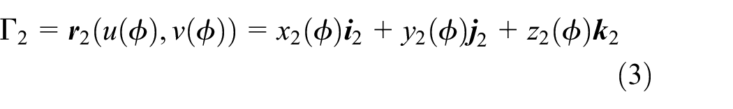
Figure 1 shows the schematic diagram of curve-surface conjugate meshing. In Figure 1, ∑1 and ∑2 are two conjugated surfaces, Γ2 is a smooth curve on ∑2, Γ1 is the curve conjugated with Γ2 on ∑1, ∑3 is a new surface which satisfies the curve-surface conjugate rule obtained by Γ1, P is the tangent point between Γ1 and Γ2 at moment t.

The schematic diagram of curve-surface conjugate meshing.
CS f , CS1, and CS2 are the reference coordinate system, the coordinate system fixed to ∑1, and the coordinate system fixed to ∑2, respectively. If the equation of the given surface ∑2 in CS2 is known as:

Where u and v are parameters of surface;
According to the envelope principle of conjugate surface, after the law of motion is given, the equation of conjugate surface ∑1 of ∑2 in CS1 can be written as:

Where
Γ2 is a smooth curve on ∑2. Due to ∑1 and ∑2 are conjugated with each other, there is a curve Γ1 conjugated with Γ2 on ∑1. If the equation of Γ2 is:
Where ϕ is the parameter of Γ2. Then the equation of Γ1 can be obtained from the meshing relationship and coordinate transformation as follows:

As single curve does not have the ability to transmit motion and power, so it is necessary to construct a new surface, namely ∑3 (as shown in Figure 1), through Γ1. Γ1 is contained in ∑3, and in the meshing process of ∑2 and ∑3, only Γ1 is tangent with ∑2 on ∑3, that is, curve-surface conjugate meshing is realized.
Construction of curve-surface conjugated face gear pair
Tooth surface equation of face gear
From the basic forming theory of face gear, then the tooth surface equation of face gear can be obtained as (see Appendix for detailed derivation):
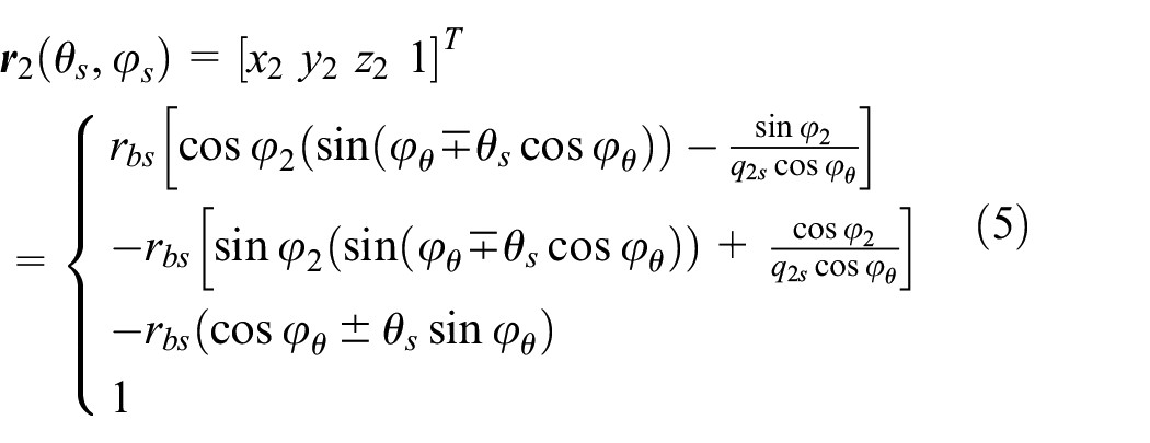
Where φ θ = φ s ±(θ os + θ s ), q2s = φ2/φ s .
The selection of contact trajectory
In order to obtain bearing contact, the conventional face gear needs to be machined by a shaper with more teeth than the actual paired pinion. The contact trajectory of the conventional orthogonal straight face gear is illustrated in Figure 2 (modulus m = 3, pressure angle α = 25°, N s = 30, N2 = 60, the tooth number of pinion N1 = 27). It can be seen from Figure 2 that the contact trajectory of the face gear pair is a curve from the top of the tooth to the root of the tooth along the direction of the tooth height, the length of the contact trajectory is short than the tooth height.

The contact trajectory of the conventional orthogonal straight face gear.
From the principle of curve-surface conjugate meshing, it is known that curve-surface conjugate meshing can realize the point contact of self-defined contact trajectory. To increase the contact trajectory length to improve the meshing performance of the face gear pair, a smooth curve in the tooth width direction is selected as the contact trajectory from the face gear tooth surface, and then the corresponding conjugate curve is obtained through the conjugate principle. Finally, based on the conjugate curve, a new pinion is constructed to mesh with the face gear to form a curve-surface conjugated face gear pair. The new face gear pair has the characteristics of point contact, and the meshing mode is to move from the outer diameter of the face gear along the predetermined contact trajectory to the inner diameter.
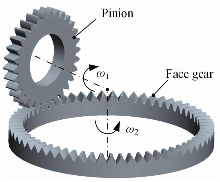
Figure 3 displays the meshing coordinate system of the curve-surface conjugated face gear pair. In Figure 3, CS1 and CS2 are the following coordinate systems fixedly connected to the pinion and the face gear, respectively; CS10 and CS20 are the fixed coordinate systems of pinion and face gear, respectively; ϕ1 and ϕ2 are the rotation angles of pinion and face gear during meshing, respectively, and ϕ2 = q21·ϕ1, q21 = N1/N2;Γ2 is a smooth curve on the surface of face gear ∑2;Γ1 is a curve of conjugate engagement with Γ2.

The meshing coordinate system of curve-surface conjugated face gear pair.
From Figure 3, the coordinate transformation matrix from CS2 to CS1 can be expressed as:

Theoretically, between the tooth top and the tooth root, there are infinitely curves from the outer diameter to the inner diameter on the tooth surface of face gear, which can be used as the contact trajectory. The contact trajectory selected here is a curve near the pitch plane of face gear and passing through the meshing pitch point. It is defined that there is a linear relationship between φ s and θ s as shown in equation (7).

Where k and b are coefficients, which can be obtained from the coordinates of a tooth surface point through the contact trajectory and the pitch point coordinates of the face gear pair.
Then the contact trajectory on the tooth surface of face gear is obtained as follows:

Figure 4 shows the designed contact trajectory on face gear tooth surface.

The designed contact trajectory on face gear tooth surface.
The contact trajectory on face gear and the corresponding contact trajectory on pinion need to meet the meshing condition. The relative speed between the contact points on the two curves can be expressed as:

Where
The unit normal vector of face gear tooth surface can be expressed as:

Then the unit normal vector of the designed contact trajectory can be obtained as follows:

The meshing equation can be expressed as follows:

Thus, the equation of Γ1 which conjugated with Γ2 is obtained as:

Figure 5 shows the contact trajectory on the pinion which is conjugated with the design contact trajectory on face gear.

The contact trajectory on pinion.
The construction of pinion tooth surface
A new pinion tooth surface ∑1′ can be obtained by sweeping the normal tooth profile Γ1 c with Γ1′ as the origin locus of the tooth profile and Γ1 as the ridge line. Figure 6 shows the schematic diagram of pinion tooth surface construction.
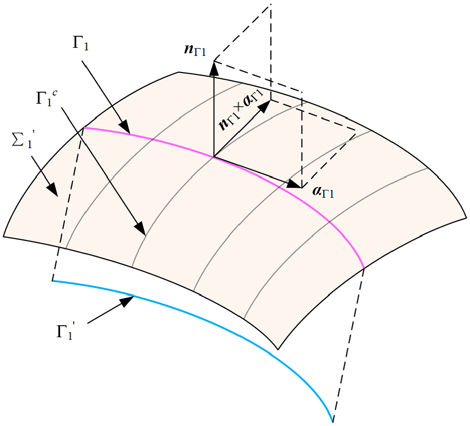
The schematic diagram of pinion tooth surface construction.
Here


Γ1′ is the normal equidistant curve of Γ1.

Where ρ is the normal distance between Γ1 and Γ1′, its value is generally as (0.8–0.95)ρmin, 23 ρmin is the minimum radius of curvature of the face gear tooth surface.
Defining the normal tooth profile Γ1c of the new pinion as an arc tooth profile. Thus, Γ1c can be described as:
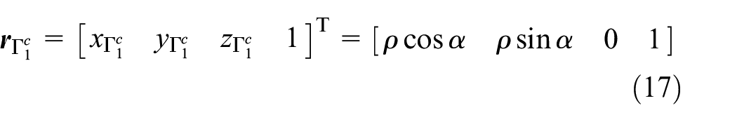
Where α is the spread angle of arc tooth profile.
Thus, the newly constructed pinion tooth surface equation is obtained as follows:

Where

Figure 7 shows the original pinion tooth surface ∑1, the newly constructed pinion tooth surface ∑1′, and the contact line Γ1 between them. The gear parameters used in the calculation are illustrated in Table 1.

The original pinion tooth surface ∑1, the newly constructed pinion tooth surface ∑1′, and the contact line Γ1 between them.
Parameters of shaper, curve pinion, and face gear.

Meshing characteristics of curve-surface conjugated face gear pair
Point contact characteristics
The designed curve-surface conjugated face gear pair can keep point contact at any time. Figure 8 shows the meshing of newly constructed pinion and face gear.

The meshing of newly constructed pinion and face gear.
Figure 9 is the schematic diagram of the meshing of curve-surface conjugated face gear pair, and the black line in is the meshing line. Figure 9(a) shows the initial position where the pinion and face gear enter meshing at the outer diameter of face gear. When the gear pair rotates through an angle, the two tooth surfaces keep point contact, and the middle position of meshing is shown in Figure 9(b). As the movement progresses, the two tooth surfaces are disengaged at the inner diameter of the face gear, as shown in Figure 9(c). As can be seen from the figures, the newly constructed curve-surface conjugated face gear pair maintains point contact at all positions of the transmission, and the instantaneous contact point is always on the meshing line. Moreover, the trajectory of the instantaneous contact point on the tooth surface of the pinion and face gear coincides with the designed contact trajectory, that is, Γ1 and Γ2.

The schematic diagram of the meshing of curve-surface conjugated face gear pair: (a) initial position, (b) middle position, (c) end position.
According to equations (5) and (18), the tooth surface points of face gear and pinion are calculated, and the 3D model of curve-surface conjugated face gear pair is obtained through the modeling software, as illustrated in Figure 10.
The 3D model of curve-surface conjugated face gear pair.
The sliding coefficient of curve-surface conjugated face gear pair
Due to the difference of the speed of meshing point, the relative sliding will occur between the two meshing tooth profiles. Under the action of pressure, the sliding will lead to the wear of tooth surface. The sliding coefficient η is used to express the sliding degree between the two meshing points. Obviously, the greater the η, the more severe the sliding, and the more serious wear of the tooth surfaces. For gear transmissions, the two tooth surfaces are pure rolling at the pitch point, so η at the pitch point is 0. Figure 11 is the schematic diagram of the sliding of tooth surface. As shown in Figure 11, at a certain moment, two contact trajectory Γ1 and Γ2 mesh at point K. After Δt time, the point on Γ1 moves from K to K1, and the arc length is ΔS1; The point on Γ2 moves from K to K2, and the arc length is ΔS2.

The schematic diagram of the sliding of tooth surface.
Therefore, the sliding coefficient of the tooth surface can be calculated as:


Where:


Then the sliding coefficient of the curve-surface conjugated face gear pair can be obtained by software, as shown in Figure 12(a). In addition, the sliding coefficient of the conventional face gear pair is calculated, as shown in Figure 12(b). In the calculation, the tooth number of the shaper and the newly constructed pinion is 30; the tooth number of the conventional involute pinion is 27; the parameters of the face gear under two modes are the same.

The sliding coefficient of two kinds of face gear pairs: (a) curve-surface conjugated face gear pair; (b) conventional face gear pair.
It can be seen from Figure 12(a), the sliding coefficient of the tooth surface of curve-surface conjugated face gear pair is between ±0.056, while that of the conventional face gear pair is between −4.84 and 0.83 (Figure 12(b)). By comparing the two, it can be seen that the sliding coefficient of the curve-surface conjugated face gear pair is much lower than that of the conventional face gear pair. This can greatly reduce the heat and wear of the tooth surface and improve the transmission performance of face gear pair. The curve-surface conjugated face gear pair has a very small sliding coefficient, which is mainly due to the freely selected contact trajectory. When the selected contact trajectory is close to the pitch plane of the face gear and the pitch line of the pinion, a very small tooth surface sliding coefficient can be achieved.
Contact analysis of curve-surface conjugated face gear pair
The installation errors will affect the transmission accuracy and transmission stability of the face gear pair and worsen the meshing situation. In the face gear transmission, the installation errors mainly include the following three kinds: (1) the angle error between the two gear axes, that is, the axis intersection angle error Δγ; (2) the shortest distance caused by the non-intersection of the two gear axes, that is, the axis intersection error Δa; (3) the displacement of the face gear along its own axis direction, that is, the axial offset error Δz. Figure 13 illustrates the misinstallation of face gear pair.

The misinstallation of face gear pair.
Where CS20 (O20-x20, y20, z20) is the fixed coordinate system of face gear under the ideal condition; CS20′ (O20′-x20′, y20′, z20′) is the actual position of the fixed coordinate system of face gear under the error condition. Then the transformation matrix for transforming CS1, CS2 into CS10 can be obtained as follows:
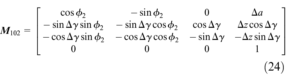
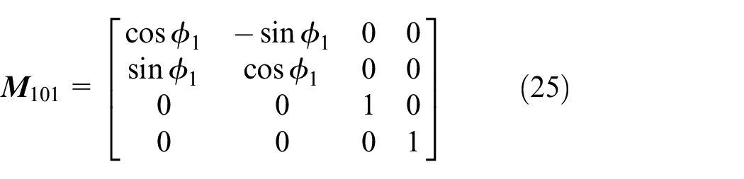
Further, the pinion and face gear tooth surfaces can be expressed in CS10, which are:


Similarly, the unit normal vector of pinion and face gear tooth surface in CS10 can be obtained as:


The pinion and face gear are tangent at the contact point at any time of transmission, so the contact point meets the following conditions.

When the pinion rotation angle ϕ1 is given, other parameters can be solved according to the above equations, so as to realize the tooth contact analysis under different conditions.
Let the pinion rotation angle ϕ1 = 0, and the face gear rotation angle ϕ2 = ϕ2*. Thus, the theoretical rotation angle of face gear can be expressed as:

Then the transmission error of face gear can be calculated as:

Figure 14 shows the contact trajectory and transmission error of face gear without installation error. It can be seen from Figure 14(a) that the TCA result coincides with the designed contact trajectory, which shows that the developed curve-surface conjugated face gear pair realizes the preset contact mode. Figure 14(b) displayed that the transmission error of the curve-surface conjugated face gear pair is 0 without installation error.

The contact trajectory and transmission error of face gear without installation error (a) contact trajectory; (b) transmission error.
Figures 15 to 17 demonstrates the contact trajectory and transmission error of the curve-surface conjugated face gear pair with installation errors Δa = ±0.1 mm, Δz = ±0.1 mm, and Δγ = ±0.05°, respectively. It can be observed from Figures 15(a) to 17(a) that in the tooth height direction, the influence of Δa on the contact trajectory is lighter than Δz and Δγ; in the tooth width direction, Δa, Δz, and Δγ will lead to obvious movement of the contact trajectory, but most of the tooth width is still involved in the meshing. Furthermore, from Figures 15(b) and (c) to 17(b) and (c), it can be observed that Δa, Δz, and Δγ will cause piecewise discontinuous transmission errors. However, within the selected error range, the maximum transmission errors caused by Δa, Δz, and Δγ are also <0.85 arc sec, which shows that the transmission error of the curve-surface conjugated face gear pair is not sensitive to the installation errors. This is an advantage for the intersecting axle gear pair used in transmission.

Contact trajectory and transmission error with installation error (a) contact trajectory; (b) transmission error, Δa = 0.1 mm; (c) transmission error, Δa = −0.1 mm. The influence of Δa on the contact trajectory in the tooth height direction is lighter than that in the tooth width direction. Δa will cause piecewise discontinuous transmission errors, but the maximum transmission erroris <0.4 arc sec.

Contact trajectory and transmission error with installation error (a) contact trajectory; (b) transmission error, Δz = 0.1 mm; (c) transmission error, Δz = −0.1 mm. The influence of Δz on the contact trajectory in the tooth height direction is lighter than that in the tooth width direction. Δz will cause piecewise discontinuous transmission errors, but the maximum transmission erroris <0.85 arc sec.

Contact trajectory and transmission error with installation error (a) contact trajectory; (b) transmission error, Δγ = 0.05°; (c) transmission error, Δγ = −0.05°. The influence of Δγ on the contact trajectory in the tooth height direction is lighter than that in the tooth width direction. Δγ will cause piecewise discontinuous transmission errors, but the maximum transmission error is <0.75 arc sec.
In addition, it is also found that the move direction of the contact trajectory caused by Δa of the same symbol is opposite to that caused by Δz and Δγ, and the changing trend of transmission error is also the same. Figure 18 shows the contact trajectory and transmission error of face gear pair with comprehensive installation errors (Δa = 0.0775 mm, Δz = 0.08 mm, Δγ = −0.02°).

The contact trajectory and transmission error of face gear pair with comprehensive installation errors Δa = 0.0775 mm, Δz = 0.08 mm, Δγ = −0.02° (a) contact trajectory; (b) transmission error.
As can be seen from Figure 18, under the comprehensive error of design, the contact trajectory of face gear pair almost coincides with the designed contact trajectory. The transmission error also presents a continuous parabola, and its maximum value is 0.076, which is more than 76% lower than the maximum value of 0.32 when Δa acts alone. It is suggested that the change of contact mode of face gear pair caused by different installation errors can be coordinated by adjusting installation parameters, and the transmission performance of face gear pair can be improved.
Conclusions
A novel face gear pair based on curve-surface conjugation is presented in this paper. According to the derivation and analysis, the following conclusions can be drawn:
A face gear pair based on curve-surface conjugation is proposed, which realizes the point contact meshing between the pinion and the face gear according to the preset contact trajectory under the condition of the same number of teeth of the pinion and shaper.
The meshing point of the newly constructed curve-surface conjugated face gear pair moves from the outer diameter to the inner diameter of the face gear, and the contact trajectory is long and the contact area is large, which is beneficial to improve the bearing capacity of the face gear pair.
The sliding coefficient of the curve-surface conjugated face gear pair is much smaller than that of the conventional face gear pair, which can greatly reduce the wear of the tooth surface and improve the transmission performance.
The transmission error of the curve-surface conjugated face gear pair is insensitive to the installation errors, which is an advantage for the intersecting axle gear transmission. Moreover, the contact mode changes of the face gear pair caused by different installation errors can be coordinated by adjusting the installation parameters, so as to improve the transmission performance of the face gear pair.
The research in this work provides a new strategy for the design of face gear pair with optimized contact mode and low sliding coefficient, and is a new attempt for the configuration design of face gear pair, which can be used to find new face gear transmission with more optimized performance. This paper presents a novel exploration of face gear pair construction methodology; however, challenges inherent in machining processes for this new gear configuration have not been thoroughly analyzed. Subsequent research could focus on investigating the influence of distinct tooth profiles on the transmission performance of curve-face conjugated face gear pairs, as well as exploring practical machining approaches for their realization.
Footnotes
Appendix
According to the position relationship of gear pair during transmission, the schematic diagram of face gear shaping as shown in Figure A1 can be obtained.
Here CSs (O s -x s , y s , z s ) is the following coordinate system of the shaper; CS2 (O2-x2, y2, z2) is the following coordinate system of the face gear; ω s is the rotational speed of the shaper; ω2 is the rotational speed of the face gear; γ is the included angle between the axis of the shaper and the face gear, that is, the shaft angle. The research object of this paper is the orthogonal face gear pair, so γ is 90°. Furthermore, the coordinate system of face gear shaping as shown in Figure A2 can be obtained.
Here CSs0 (O s 0-x s 0, y s 0, z s 0) is the fixed coordinate system of the shaper; CS20 (O20-x20, y20, z20) is the fixed coordinate system of the face gear; φ s is the rotation angle of the shaper during machining; φ2 is the rotation angle of the face gear during machining, and φ2 = q2s·φs, q2s = N s /N2, N s is the tooth number of shaper, N2 is the tooth number of face gear. The tooth profile of involute shaper is shown in Figure A3, so the tooth profile equation of shaper can be expressed as
Here CSs represents the following coordinate system of the shaper; θ s is the flare angle of point S(S′) on the involute; θ os is the space width half angle, which determines a half of the width of the tooth space on the basic circle; r bs is the radius of the basic circle; r ps is the radius of the reference circle; u s is the axial parameter of point S(S′). The upper and lower parts of the sign in x s indicate the right-flank and the left-flank, respectively.
The unit normal vector of shaper tooth surface is:
So that it can be obtained by meshing theory:
Where
The coordinate system of the shaper when machining the face gear is shown in Figure A2, and the coordinate transformation matrix from CS s to CS2 is obtained as follows:
The θ os in equation (A1) is determined by the following formula:
Here α s is the pressure angle of the shaper, invα s is the involute function of α s , that is:
The relative velocity at the meshing point P is:
The meshing condition of the two tooth surfaces is:
From equation (A8) it can be get that:
By introducing equation (A9) into the first formula of equation (A3), the tooth surface equation of orthogonal straight face gear expressed by the parameters θ s and φ s , namely equation (5), is obtained.
Handling Editor: Chenhui Liang
Author contributions
Jun Wang: methodology, data curation, validation, writing – original draft, investigation, visualization. Jianpeng Dong: software, writing – review and editing, formal analysis. Sibao Wang: funding acquisition, project administration. Yuliang Xiao: conceptualization, resources.
Funding
The author(s) received no financial support for the research, authorship, and/or publication of this article.
Declaration of conflicting interests
The author(s) declared no potential conflicts of interest with respect to the research, authorship, and/or publication of this article.
Data availability statement
The data that has been used is contained in the paper.